Allen-Bradley 1794-IT8 User Manual
Thermocouple/millivolt input module
Hide thumbs
Also See for 1794-IT8:
- Installation instructions manual (16 pages) ,
- Installation instructions manual (7 pages)

Related Manuals for Allen-Bradley 1794-IT8


Summary of Contents for Allen-Bradley 1794-IT8
- Page 1 Allen-Bradley User Thermocouple/ Millivolt Input Manual Module (Cat. No. 1794-IT8)
- Page 2 DeviceNet, DeviceNetManager, and RediSTATION are trademarks of Allen-Bradley Company, Inc. PLC, PLC–2, PLC–3, and PLC–5 are registered trademarks of Allen-Bradley Company, Inc. Windows is a trademark of Microsoft. Microsoft is a registered trademark of Microsoft IBM is a registered trademark of International Business Machines, Incorporated.
- Page 3 Summary of Changes Summary of Changes The information below summarizes the changes to the company-wide templates since the last release. New Information The following new information has been added to this manual: the “L” type thermocouple selection has been added for use in some European markets.
- Page 4 soc–ii Summary of Changes Publication 1794-6.5.7 – April 1997...
-
Page 5: Table Of Contents
Table of Contents Overview of Flex I/O and Chapter 1 your Thermocouple/mV Chapter Objectives ........1–1 Module The FLEX I/O System... - Page 6 Mapping Data for the Analog Modules ..... . 4–4 Thermocouple/mV Input Module (1794-IT8) Image Table Mapping 4–4 Thermocouple/mV Input Module (1794-IT8) Read .
- Page 7 Table of Contents Calibrating Your Thermocouple/mV Module using DeviceNetManager Software (Cat. No. 1787-MGR) ......6–9 Offset Calibration .
- Page 8 Table of Contents Publication 1794-6.5.7...
- Page 9 Audience We assume that you have previously used an Allen-Bradley programmable controller, that you are familiar with its features, and that you are familiar with the terminology we use. If not, read the user manual for your processor before reading this manual.
- Page 10 P–2 Using This Manual Conventions We use these conventions in this manual: In this manual, we show: Like this: that there is more information about a topic in another chapter in this manual that there is more information about the topic in another manual More For Additional Information...
-
Page 11: Overview Of Flex I/O And
How FLEX I/O Analog FLEX I/O thermocouple/mV modules are block transfer modules Modules Communicate that interface analog signals with any Allen-Bradley programmable with Programmable controllers that have block transfer capability. Block transfer Controllers programming moves input or output data words between the module’s memory and a designated area in the processor data table. -
Page 12: Typical Communication Between An Adapter And A Module
The illustration describes the communication process. Typical Communication Between an Adapter and a Module The adapter transfers your configuration data External devices transmit to the module using a BTW. analog signals to the module. Flexbus Allen-Bradley Allen-Bradley 1794–IT8 THERMOCOUPLE INPUT 8 CHANNEL 24VDC ADAPTER LOCAL... -
Page 13: Features Of Your Modules
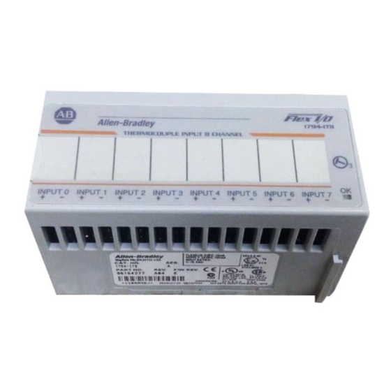
Overview of FLEX I/O and your Thermocouple/mV Module 1–3 Features of your Modules The module label identifies the keyswitch position, wiring and module type. A removable label provides space for writing individual designations per your application. 1794-IT8 Module Type Allen-Bradley 1794–IT8 THERMOCOUPLE INPUT 8 CHANNEL Removable Label... - Page 14 1–4 Overview of FLEX I/O and your Thermocouple/mV Module Publication 1794-6.5.7...
-
Page 15: How To Install Your
Chapter How to Install Your Thermocouple/mV Input Module In this chapter, we tell you: how to install your module how to set the module keyswitch how to wire the terminal base about the indicators Before You Install Your Before installing your thermocouple/mV module in the I/O chassis: Input Module You need to: As described under:... -
Page 16: Low Voltage Directive
Programmable Controllers, Part 2 – Equipment Requirements and Tests. For specific information required by EN 61131-2, see the appropriate sections in this publication, as well as the following Allen-Bradley publications: Industrial Automation Wiring and Grounding Guidelines For Noise Immunity, publication 1770-4.1 Guidelines for Handling Lithium Batteries, publication AG-5.4... -
Page 17: Wiring The Terminal Base Units (1794-Tb2 And -Tb3 Shown)
How to Install Your Thermocouple/mV Input Module 2–3 Methods of wiring the terminal base units are shown in the illustration below. Wiring the Terminal Base Units (1794-TB2 and -TB3 shown) ATTENTION: Do not daisy chain power or ground from the thermocouple terminal base unit to any ac or dc discrete module terminal base unit. -
Page 18: Installing The Module
2–4 How to Install Your Thermocouple/mV Input Module Installing the Module The thermocouple/mV module mounts on a 1794-TB2, -TB3 or -TB3T terminal base unit. Important: You must use a 1794-TB3T terminal base unit if you are using the thermocouple/mV module for thermocouple inputs. -
Page 19: Connecting Wiring For The Thermocouple/Mv Module
Compatible terminal base unit are: Module 1794-TB2 1794-TB3 1794-TB3T 1794-IT8 The 1794-TB3T terminal base unit contains connections for cold junction compensation for use with thermocouple modules. For millivolt inputs only. 1794-TB2 and 1794-TB3 1794-TB3T 1 2 3 4 5... - Page 20 1794-TB2 9 10 11 12 13 14 15 0 –15 16–33 34–51 1794-TB3, -TB3T Table 2.A Wiring connections for the 1794-IT8 Thermocouple Input Module 1794-TB2, -TB3 Terminal Base Units 1794-TB3T Terminal Base Unit Thermocouple Thermocouple High Signal Low Signal Shield...
-
Page 21: Example Of Millivolt Input Wiring To A 1794-Tb3 Terminal Base Unit
Channel 0 (Terminals 0, 1 and 17) Example of 3-wire Thermocouple Wiring to a 1794-TB3T Temperature Terminal Base Unit 0 –15 16–33 34–51 1794-TB3T Cold Junction Compensator Allen-Bradley PN 969424–01 (2 supplied with module) – Channel 0 (Terminals 0, 1 and 39) Publication 1794-6.5.7... -
Page 22: Module Indicators
How to Install Your Thermocouple/mV Input Module Module Indicators The thermocouple/mV module has one status indicator that is on when power is applied to the module. This indicator has 3 different states: Allen-Bradley 1794–IT8 THERMOCOUPLE INPUT 8 CHANNEL INPUT 0 INPUT 1... -
Page 23: Module Programming
Chapter Module Programming Chapter Objectives In this chapter, we tell you about: block transfer programming sample programs for the PLC-3 and PLC-5 processors Block Transfer Your thermocouple/mV module communicates with the processor Programming through bidirectional block transfers. This is the sequential operation of both read and write block transfer instructions. -
Page 24: Sample Programs For Flex I/O Analog Modules
3–2 Module Programming Sample programs for The following sample programs show you how to use your analog FLEX I/O Analog Modules module efficiently when operating with a programmable controller. These programs show you how to: configure the module read data from the module These example programs illustrate the minimum programming required for communication to take place. -
Page 25: Plc-5 Programming
Module Programming 3–3 PLC-5 Programming The PLC-5 program is very similar to the PLC-3 program with the following exceptions: Block transfer enable bits are used instead of done bits as the conditions on each rung. Separate block transfer control files are used for the block transfer instructions. -
Page 26: Plc-2 Programming
3–4 Module Programming PLC-2 Programming The 1794 analog I/O modules are not recommended for use with PLC-2 family programmable controllers due to the number of digits needed for high resolution. Chapter Summary In this chapter, you learned how to program your programmable controller. -
Page 27: Writing Configuration To
Chapter Writing Configuration to and Reading Status from your Module with a Remote I/O Adapter Chapter Objectives In this chapter, we tell you about: configuring your module’s features entering your data reading data from your module the read block format Configuring Your Because of the wide variety of possible configurations, you must Thermocouple/mV Module... -
Page 28: Range Selection
4–2 Writing Configuration to and Reading Status from your Module with a Remote I/O Adapter Range Selection Individual input channels are configurable to operate with the following sensor types: Sensor Type Range Voltage Millivolt –76.50 to +76.50mV Thermocouple r ocoupl Type B 300 to 1800 Type E... -
Page 29: Hardware First Notch Filter
Writing Configuration to and Reading Status from your Module with a Remote I/O Adapter 4–3 You select input scaling using the designated words of the write block transfer instruction. Refer to the Bit/Word description for write word 0, bits 00 and 01. Hardware First Notch Filter A hardware filter in the analog to digital converter lets you select a frequency for the first notch of the filter. -
Page 30: Reading Data From Your Module
The module uses up to 11 words of input image and up to 3 words of output image. Each word is composed of 16 bits. Thermocouple/mV Input Module (1794-IT8) Image Table Mapping Module Image Reserved Input Data Channel 0... -
Page 31: Thermocouple/Mv Input Module (1794-It8) Write
Thermocouple 0 Type Thermocouple 7 Type Thermocouple 6 Type Thermocouple 5 Type Thermocouple 4 Type Where: FDF = fixed digital filter bit Word/Bit Descriptions for the 1794-IT8 Thermocouple/mV Input Module Decimal Bit Word Description (Octal Bit) Read Word 0 00–15 (00–17) - Page 32 4–6 Writing Configuration to and Reading Status from your Module with a Remote I/O Adapter Decimal Bit Word Description (Octal Bit) 00–01 (00–01) Module Data Type Write Word 0 Definition C (default) Bipolar counts scaled between –32768 and +32767 Unipolar counts scaled between 0 and 65535 Bit 02 (02) Fixed Digital Filter –...
-
Page 33: Chapter Summary
Writing Configuration to and Reading Status from your Module with a Remote I/O Adapter 4–7 Decimal Bit Word Description (Octal Bit) 00–03 (00–03) Channel 0 Thermocouple Type Write Word 1 Thermocouple Type – Range Millivolts (default) 300 to 1800 (572 to 3272 –230 to 1000 C (–382 to 1832 –195 to 1200... - Page 34 4–8 Writing Configuration to and Reading Status from your Module with a Remote I/O Adapter Publication 1794-6.5.7 – April 1997...
-
Page 35: How Communication Takes
Chapter How Communication Takes Place and I/O Image Table Mapping with the DeviceNet Adapter Chapter Objectives In this chapter, we tell you about: DeviceNetManager software I/O structure image table mapping factory defaults About DeviceNet Manager DeviceNetManager software is a software tool used to configure your Flex I/O DeviceNet adapter and its related modules. -
Page 36: Adapter Input Status Word
5–2 How Communication Takes Place and I/O Image Table Mapping with the DeviceNet Adapter Adapter Input Status Word The input status word consists of: I/O module fault bits – 1 status bit for each slot node address changed – 1 bit I/O status –... -
Page 37: System Throughput
The number of channels included in each input scan also affects system throughput. Mapping Data into the FLEX I/O thermocouple module data table mapping is shown below. Image Table Thermocouple/mV Input Module (1794-IT8) Image Table Mapping Module Image Reserved Input Data Channel 0 Input Data Channel 1... -
Page 38: Thermocouple/Mv Input Module (1794-It8) Write
Write Word 3 Thermocouple 7 Type Thermocouple 6 Type Thermocouple 5 Type Thermocouple 4 Type Where: FDF = fixed digital filter bit Word/Bit Descriptions for the 1794-IT8 Thermocouple/mV Input Module Decimal Bit Word Description (Octal Bit) Read Word 1 00–15 (00–17) - Page 39 How Communication Takes Place and I/O Image Table Mapping with the DeviceNet Adapter 5–5 Decimal Bit Word Description (Octal Bit) 03 (03) Powerup bit – this bit is set (1) until configuration data is received by the module. Read Word 11 continu continued 04–06 (04–06)
- Page 40 5–6 How Communication Takes Place and I/O Image Table Mapping with the DeviceNet Adapter Decimal Bit Word Description (Octal Bit) 00–03 (00–03) Channel 0 Thermocouple Type Write Word 2 Thermocouple Type – Range Millivolts (default) 300 to 1800 (572 to 3272 –230 to 1000 C (–382 to 1832 –195 to 1200...
-
Page 41: Defaults
Number Default Default Default Default 1794-IT8 8 Thermocouple Input Factory defaults are the values assigned by the adapter when you: first power up the system, and no previous stored settings have been applied. For analog modules, the defaults reflect the actual number of input words/output words. - Page 42 5–8 How Communication Takes Place and I/O Image Table Mapping with the DeviceNet Adapter Publication 1794-6.5.7 – April 1997...
-
Page 43: Calibrating Your Module
Chapter Calibrating Your Module Chapter Objective In this chapter we tell you: what tools are needed to calibrate how to calibrate out lead wire resistance calibrate your module manually calibrate your module using DeviceNetManager software General Information Your module is shipped to you already calibrated. If a calibration check is required,follow the procedure below. -
Page 44: Tools And Equipment
6–2 Calibrating Your Module Tools and Equipment In order to calibrate your thermocouple input module you will need the following tools and equipment: Tool or Equipment Description Analogic 3100, Data Precision 8200 0–100mV, 1µV resolution Precision Voltage Source or equivalent Ectron Corporation Thermocouple Simulator Thermocouple Simulator/Calibrator... -
Page 45: Manually Calibrating Your Thermocouple/Mv Input Module
Calibrating Your Module 6–3 13 14 0 –15 16–33 34–51 1794-TB3, -TB3T a. Remove the decade box and voltage source. b. Reconnect the lead wires to the input terminals for this channel. Thermocouple c. Repeat this procedure for the remaining channels. Sensor Manually Calibrating your You must calibrate the module in a FLEX I/O system. -
Page 46: Flow Chart For Calibration Procedure
6–4 Calibrating Your Module Flow Chart for Calibration Procedure Apply reference signal for offset Apply reference signal for gain calibration to each channel to calibration to each channel to be calibrated. be calibrated. Set corresponding bits in the Retain corresponding bits in calibration mask and set cal the calibration mask and set Hi/Lo = 0... -
Page 47: Calibration Setups
Calibrating Your Module 6–5 Calibration Setups Using a Precision Voltage Source 13 14 0 –15 16–33 34–51 These terminals not on 1794-TB2 Precision Voltage Source 1794-TB2, -TB3 Note: Use 1794-TB2 and -TB3 terminal base units for millivolt inputs only. 12 13 14 0 –15 16–33 34–51... -
Page 48: Read/Write Words For Calibration
6–6 Calibrating Your Module Read/Write Words for Calibration Dec. Bit Octal Bit Read Word 10 Diagnostic Status Done Range Struct over Under Cal hi Write Word 0 8-Bit Calibration Mask Filter Cutoff Data Type Cal lo Offset Calibration Inputs can be calibrated one at a time or all at once. To calibrate the offsets for all inputs at once, proceed as follows: 1. -
Page 49: Gain Calibration
Calibrating Your Module 6–7 Gain Calibration After completing the offset calibration, proceed with the gain calibration. 1. Apply power to the module for 40 minutes before calibrating. 2. Connect 75.000mV across each input channel. Connect all high signal terminals together and attach to the positive lead from the precision voltage source. -
Page 50: Software (Cat. No. 1787-Mgr)
6–8 Calibrating Your Module Calibrating Your The following procedure assumes that you are using Thermocouple/mV Module DeviceNetManager software (cat. no. 1787-MGR) and have the using DeviceNetManager thermocouple/mV module installed in a working system. Software (Cat. No. 1787-MGR) Offset Calibration Inputs can be calibrated one at a time or all at once. To calibrate the offsets for all inputs at once, proceed as follows: 1. - Page 51 Calibrating Your Module 6–9 4. Click on to get to the calibration screen. 5. Click on the channels you want to calibrate. 6. Click on the radio button for offset calibration. Then click on 7. When calibration is complete, a notification will appear on the calibration status line.
-
Page 52: Gain Calibration
6–10 Calibrating Your Module Gain Calibration Make sure that you have calibrated the offset for this channel before calibrating the gain. 1. Connect 75.000mV across each input channel. Connect all high signal terminals together and attach to the positive lead from the precision voltage source. - Page 53 Calibrating Your Module 6–11 button populates the screen with the actual values appearing at the inputs. Note that there is an implied decimal point to the left of the last 2 digits.. For example, channel 0 data value reads 7500. The actual reading is 75.00mV. After both offset and gain calibrations are successful, click on You will be returned to the module configuration screen.
- Page 54 6–12 Calibrating Your Module If you attempt to close without saving your configuration information by clicking on the button, you will be prompted to save the changes. Publication 1794-6.5.7 – April 1997...
-
Page 55: Specifications
Appendix Specifications Specifications – 1794-IT8 Thermocouple/mV Input Module Number of Inputs 8 Channels Module Location Cat. No. 1794-TB2, -TB3 and -TB3T Terminal Base Units Nominal Input Voltage Ranges +76.5mV Supported Thermocouple Types Type B: 300 to 1800 (572 to 3272... - Page 56 A–2 Specifications Specifications – 1794-IT8 Thermocouple/mV Input Module Thermal Dissipation Maximum 10.2 BTU/hr @ 31.2V dc Keyswitch Position General Specifications External dc Power Supply Voltage 24V dc nominal Voltage Range 19.2 to 31.2V dc (includes 5% ac ripple) 19.2V dc for ambient temperatures less than 55 24V dc for ambient temperatures less than 55 31.2V dc for ambient temperatures less than 40...
-
Page 57: Derating Curve
Specifications A–3 Derating Curve User Applied 24V dc Supply versus Ambient Temperature 31.2 24.0 The area within the curve represents the safe operating range for the module under various conditions of user supplied 24V dc supply voltages and ambient temperatures. 19.2 C 55 = Safe operating area... -
Page 58: Type E Thermocouple
A–4 Specifications Type E Thermocouple Resolution 1000Hz 500Hz 250Hz 10–100Hz 64.00 16.00 4.00 0.50 115.2 28.80 7.20 0.90 51.20 12.80 3.20 0.40 92.16 23.04 5.76 0.72 38.40 9.60 2.40 0.30 69.12 17.28 4.32 0.54 25.60 12.80 1.60 0.20 46.08 11.52 2.88 0.36 12.80... -
Page 59: Type J Thermocouple
Specifications A–5 Type J Thermocouple Resolution 1000Hz 500Hz 250Hz 10–100Hz 17.92 4.480 1.120 0.140 32.25 8.064 2.016 0.252 3.840 15.36 0.960 0.120 27.65 6.912 1.728 0.216 12.80 3.200 0.800 0.100 23.04 5.760 1.440 0.180 10.24 2.560 0.640 0.080 18.43 4.608 1.152 0.144 7.680... -
Page 60: Type R Thermocouple
A–6 Specifications Type R Thermocouple Resolution 1000Hz 500Hz 250Hz 10–100Hz 102.4 25.60 6.40 0.80 184.3 46.08 11.52 1.44 76.80 19.20 4.80 0.60 138.2 34.56 8.64 1.08 51.20 12.80 3.20 0.40 92.16 23.04 5.76 0.72 25.60 6.40 1.60 0.20 46.08 11.52 2.88 0.36 –300... -
Page 61: Type T Thermocouple
Specifications A–7 Type T Thermocouple Resolution 1000Hz 500Hz 250Hz 10–100Hz 102.4 25.60 6.40 0.80 184.3 46.08 11.52 1.44 89.60 22.40 5.60 0.70 161.3 40.32 10.08 1.26 76.80 19.20 4.80 0.60 138.2 34.56 8.64 1.08 64.00 16.00 4.00 0.50 115.2 28.80 7.20 0.90 51.20... -
Page 62: Worst Case Accuracy For The Thermocouple/Mv Module
A–8 Specifications Type L Thermocouple Resolution 1000Hz 500Hz 250Hz 10–100Hz 93.69 11.71 1.46 0.18 200.6 53.0 34.6 32.3 68.09 8.51 1.06 0.13 154.5 47.3 33.9 32.2 42.49 5.31 0.66 0.08 108.4 41.5 33.1 32.1 17.04 2.13 0.26 0.03 62.6 35.8 32.4 32.0 –150... -
Page 63: Error Due To Open Circuit Current Through Loop Resistance
Specifications A–9 Error Due to Open Circuit Current Through Loop Resistance Input Type Error per Ohm of Loop Resistance 0.091 0.164 0.013 0.023 0.016 0.029 0.024 0.043 0.076 0.137 0.083 0.149 0.022 0.040 0.028 0.050 0.055 0.099 0.015 0.028 0.417µV (2.4Ω = 1 LSB of error) Worst Case Repeatability for the Thermocouple/mV Input Module Repeatability with Filter Repeatability without Filter... - Page 64 A–10 Specifications Publication 1794-6.5.7 – March 1997...
-
Page 65: Thermocouple Restrictions
Appendix Thermocouple Restrictions (Extracted from NBS Monograph 125 (IPTS-68)) General Following are some restrictions extracted from NBS Monograph 125 (IPTS–68) issued March 1974 on thermocouples B, E, J, K, R, S and T: B (Platinum – 30% Rhodium vs Platinum – 6% Rhodium) Type Thermocouples “The ASTM manual STP 470 [1970] indicates the following restrictions on the use of B type thermocouples at high temperatures:... -
Page 66: E (Nickel-Chromium Vs Copper-Nickel
B–2 Thermocouple Restrictions E (Nickel–Chromium vs Copper–Nickel) Type Thermocouple - Page 67 Thermocouple Restrictions B–3 “Type J thermocouples are recommended by the ASTM [1970] for use in the temperature range from 0 to 760C in vacuum, oxidizing, reducing or inert atmospheres. If used for extended times above 500C, heavy gage wires are recommended because the oxidation rate is rapid at elevated temperatures.”...
-
Page 68: K (Nickel-Chromium Vs Nickel-Aluminum) Type Thermocouple
B–4 Thermocouple Restrictions K (Nickel–Chromium vs Nickel–Aluminum) Type Thermocouple “This type is more resistant to oxidation at elevated temperatures than the Types E, J or T thermocouples and consequently it finds wide application at temperatures above 500C.” “Type K thermocouples may be used at” liquid hydrogen “temperatures. -
Page 69: R (Platinum-13% Rhodium Vs Platinum) And S (Platinum-10% Rhodium Vs Platinum) Type Thermocouples
Thermocouple Restrictions B–5 R (Platinum–13% Rhodium vs Platinum) and S (Platinum–10% Rhodium vs Platinum) Type Thermocouples “The ASTM manual STP 470 [1970] indicates the following restrictions on the use of S {and R} type thermocouples at high temperatures: They should not be used in reducing atmospheres, nor in those containing metallic vapor (such as lead or zinc), nonmetallic vapors (such as arsenic, phosphorous or sulfur) or easily reduced oxides, unless suitably protected with nonmetallic protecting tubes. - Page 70 B–6 Thermocouple Restrictions “Type T thermocouples are recommended by the ASTM [1970] for use in the temperature range from –184 to 371C in vacuum or in oxidizing, reducing or inert atmospheres. The recommended upper temperature limit for continuous service of protected Type T thermocouples is set at 371C for AWG 14 (1.6mm) thermoelements, since Type TP thermoelements oxidize rapidly above this temperature.
- Page 71 3–1 block transfer read, 4–4 1794-IT8, 4–4, 5–3 block transfer write example 1794-IT8, 4–5, 5–4 thermocouple/1794-TB3, 2–7 configuration block, 1794-IT8, 4–5, 5–4 thermocouple/1794-TB3T, 2–7 input range selection, 4–2 features, of the module, 1–3 first notch filter, 4–3 calibration gain, 6–8 flow chart, calibration, 6–5...
- Page 72 E thermocouple, A–3 type J thermocouple, A–4 manual calibration, 6–4 type K thermocouple, A–5 type N thermocouple, A–7 mapping, 1794-IT8, 4–4, 5–3 type R thermocouple, A–5 module, shipping state, 6–1 type S thermocouple, A–6 module fault, 5–2 type T thermocouple, A–6 module features, 1–3...
- Page 73 Sequence What is not in the right order? Other Comments Use back for more comments. Your Name Location/Phone Return to: Marketing Communications, Allen-Bradley Co., 1 Allen-Bradley Drive, Mayfield Hts., OH 44124-6118 Phone: (216)646-3176 FAX: (216)646-4320 Publication ICCG-5.21-August 1995 PN 955107-82...
- Page 74 PLEASE FASTEN HERE (DO NOT STAPLE) Other Comments PLEASE FOLD HERE NO POSTAGE NECESSARY IF MAILED IN THE UNITED STATES BUSINESS REPLY MAIL FIRST-CLASS MAIL PERMIT NO. 18235 CLEVELAND OH POSTAGE WILL BE PAID BY THE ADDRESSEE 1 ALLEN BRADLEY DR MAYFIELD HEIGHTS OH 44124-9705...
- Page 75 Support Services At Allen-Bradley, customer service means experienced representatives at Customer Support Centers in key cities throughout the world for sales service and support. Our value-added services include: Technical Support SupportPlus programs telephone support and 24-hour emergency hotline software and documentation updates...
- Page 76 Philippines Poland Portugal Puerto Rico Qatar Romania Russia–CIS Saudi Arabia Singapore Slovakia Slovenia South Africa, Republic Spain Sweden Switzerland Taiwan Thailand Turkey United Arab Emirates United Kingdom United States Uruguay Venezuela Yugoslavia Allen-Bradley Headquarters, 1201 South Second Street, Milwaukee, WI 53204 USA, Tel: (1) 414 382-2000 Fax: (1) 414 382-4444 Publication 1794-6.5.7 – April 1997 Template revised June 23, 1995 Publication 1794-6.5.7 –...