Table of Contents
Quick Links
Table of Contents

Related Manuals for Allen-Bradley Compact 5000 Series


Summary of Contents for Allen-Bradley Compact 5000 Series
- Page 1 User Manual Original Instructions Compact 5000 I/O Digital Modules Catalog Numbers 5069-IA16, 5069-IB8S, 5069-IB8SK, 5069-IB16, 5069-IB16F, 5069-IB16K, 5069-IB6F-3W, 5069-OA16, 5069-OB8, 5069-OBV8S, 5069-OBV8SK, 5069-OB16, 5069-OB16F, 5069-OB16K, 5069-OW4I, 5069-OW16, 5069-OX4I...
- Page 2 Important User Information Read this document and the documents listed in the additional resources section about installation, configuration, and operation of this equipment before you install, configure, operate, or maintain this product. Users are required to familiarize themselves with installation and wiring instructions in addition to requirements of all applicable codes, laws, and standards.
-
Page 3: Table Of Contents
Table of Contents Preface ............. .11 Summary of Changes . - Page 4 Table of Contents Input Module Operation ........49 Local Compact 5000 I/O Digital Input Modules.
- Page 5 Table of Contents Chapter 3 Input Module Features Multiple Input Module Types ........82 Data Transfer at RPI or Change of State .
- Page 6 Table of Contents Thermal Shutoff ..........118 Thermal Shutoff with Standard Output Modules .
- Page 7 Table of Contents Chapter 6 Configure a Standard Module Before You Begin..........150 Create a New Module .
- Page 8 Table of Contents Chapter 7 Configure and Replace Before You Begin..........192 Create a New Module .
- Page 9 Table of Contents Appendix B Module Tag Definitions Name Conventions......... . . 232 Access the Tags .
- Page 10 Table of Contents 5069-IB8S and 5069-IB8SK Module Tags..... . 268 Input Tags ..........268 Output Tags .
-
Page 11: Preface
Preface This manual describes how to use Compact 5000™ I/O digital modules in Logix 5000™ control systems. Make sure that you are familiar with the following: • Use of a controller in a Logix 5000 control system. • Use of an EtherNet/IP™ network, if the digital I/O modules are used remotely. -
Page 12: Graphics Indicate Feature Support
Preface Graphics Indicate Throughout this manual, graphics appear with section titles to indicate the digital I/O modules that support the feature that is described in that section. Feature Support If both standard and safety modules support a feature, you see icons for both types. -
Page 13: Terminology
Preface Terminology The following table defines terms that are used in this manual. Table 1 - Terminology Used throughout the Manual Abbreviation Full Term Definition 1oo2 One out of Two Identifies the programmable electronic controller architecture. CIP™ Common Industrial Protocol An industrial communication protocol that is used by Logix 5000-based automation systems on EtherNet/IP, ControlNet®, and DeviceNet®... -
Page 14: Additional Resources
Preface Additional Resources The following resources contain information about related products from Rockwell Automation. Table 2 - Additional Resources to Use with Compact 5000 I/O Digital Modules Resource Description Compact 5000 I/O Digital 16-point Sinking Input Describes how to install and wire the 5069-IB16, Modules Installation Instructions, publication 5069-IB16F, and 5069-IB16K input modules. - Page 15 Provides declarations of conformity, certificates, and other certification details. http://www.rockwellautomation.com/ rockwellautomation/certification/overview.page You can view or download publications at http://literature.rockwellautomation.com/. To order paper copies of technical documentation, contact your local Allen-Bradley distributor or Rockwell Automation® sales representative. Rockwell Automation Publication 5069-UM004A-EN-P - April 2019...
- Page 16 Preface Notes: Rockwell Automation Publication 5069-UM004A-EN-P - April 2019...
-
Page 17: Digital Module Operation In A Control System
Chapter Digital Module Operation in a Control System Topic Page Controller and Software Compatibility Types of Modules Module Overview Local I/O Modules or Remote I/O Modules Secure Access to the System Ownership Construct a System Power the Modules Configure the Modules Input Module Operation Output Module Operation Listen Only... -
Page 18: Controller And Software Compatibility
Chapter 1 Digital Module Operation in a Control System Controller and Software Controller and programming software compatibility requirements apply when you use Compact 5000 I/O digital modules. A module type and how it is used Compatibility affect which requirements apply. You must also consider Logix Designer application version requirements when Standard Modules you design your system. - Page 19 Digital Module Operation in a Control System Chapter 1 Table 3 describes the module compatibility requirements when you use Compact 5000 I/O digital modules with Logix 5000 controllers. Table 3 - Compact 5000 I/O Digital Modules Controller and Software Compatibility Requirements Controllers Logix Designer Modules...
- Page 20 Chapter 1 Digital Module Operation in a Control System Table 3 - Compact 5000 I/O Digital Modules Controller and Software Compatibility Requirements Controllers Logix Designer Modules Location System Cat. Nos. Application Safety Modules Local Compact GuardLogix 5380 5069-L306ERS2, 5069-L306ERMS2, 5069-L310ERS2, 5069- Version 32.00.00 or later L310ERMS2, 5069-L320ERS2, 5069-L320ERS2K, 5069- 5069-IB8S,...
-
Page 21: Types Of Modules
Digital Module Operation in a Control System Chapter 1 Types of Modules Table 4 describes the Compact 5000 I/O digital modules. Table 4 - Compact 5000 I/O Digital Modules Standard Modules Module Type Cat. No. Description DC INPUT DC INPUT DC OUTPUT ANALOG INPUT ANALOG OUTPUT... -
Page 22: Module Overview
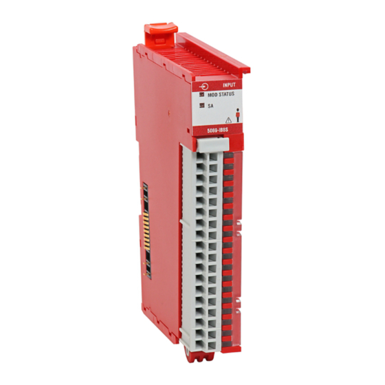
Chapter 1 Digital Module Operation in a Control System Module Overview Figure 1 shows the parts of a Compact 5000 I/O digital module. IMPORTANT Compact 5000 I/O safety modules look the same from the front with the Standard Modules exception that the safety modules have a red housing DC INPUT DC INPUT... - Page 23 Digital Module Operation in a Control System Chapter 1 Table 5 - Compact 5000 I/O Digital Module Parts Item Item Description DIN rail latch Locks the module on the DIN rail. Module and Standard modules: power status • STATUS - Displays the status of communication and module health. indicators Safety modules: •...
-
Page 24: Local I/O Modules Or Remote I/O Modules
Chapter 1 Digital Module Operation in a Control System Local I/O Modules or You can use Compact 5000 I/O digital modules as local or remote I/O modules, with some restrictions that are based on the module and Remote I/O Modules controller type. -
Page 25: Remote I/O Modules
Digital Module Operation in a Control System Chapter 1 Remote I/O Modules When Compact 5000 I/O digital modules reside in a separate location from Logix 5000 controllers, they are remote I/O modules. Remote Compact 5000 I/O digital modules are accessible over an EtherNet/IP™ network via a Compact 5000 I/O EtherNet/IP adapter. - Page 26 Chapter 1 Digital Module Operation in a Control System Figure 4 shows remote Compact 5000 I/O safety modules in a Compact GuardLogix 5380 control application. Figure 4 - Remote Compact 5000 I/O Safety Modules in a Compact GuardLogix 5380 Control Application Compact GuardLogix 5380 Controller Compact 5000 I/O Digital Modules Compact 5000 I/O EtherNet/IP Adapter...
- Page 27 Digital Module Operation in a Control System Chapter 1 Figure 5 shows remote Compact 5000 I/O safety modules in a GuardLogix 5580 control application. Figure 5 - Remote Compact 5000 I/O Safety Modules in a GuardLogix 5580 Control Application GuardLogix 5580 Safety Controller GuardLogix 1756-L8SP Safety Partner Compact 5000 I/O EtherNet/IP Adapter Compact 5000 I/O Safety Modules...
-
Page 28: Secure Access To The System
Chapter 1 Digital Module Operation in a Control System Secure Access to the System To secure access to a Logix 5000 controller, Compact 5000 EtherNet/IP adapter, or I/O module by authorized users only, consider the following options: Standard Modules • Password protect the source and execution of the control program. DC INPUT DC INPUT DC OUTPUT... -
Page 29: Ownership
Digital Module Operation in a Control System Chapter 1 Ownership Every I/O module in a Logix 5000 control system must be owned by a controller, also known as the owner-controller. When a Compact 5000 I/O digital module is used in a Logix 5000 control system, the owner-controller Standard Modules performs the following: DC INPUT... -
Page 30: Configuration Changes In An Input Module With
Chapter 1 Digital Module Operation in a Control System • The controllers that do maintain, but do not ‘own’ , the module configuration are similar to Listen-only controllers. The difference between the controllers is that the controllers that maintain, but do not own, the module configuration can use a Multicast or Unicast connection over the EtherNet/IP network. -
Page 31: Construct A System
Digital Module Operation in a Control System Chapter 1 To help prevent other owner-controllers from receiving potentially erroneous data, use the following steps when changing the configuration of a module in a multiple owner scenario while online. 1. For each owner-controller, inhibit the connection to the module either in the software on the Connection tab or the message dialog box warning you of the multiple owner condition. -
Page 32: Remote I/O Modules
Chapter 1 Digital Module Operation in a Control System Remote I/O Modules Complete the following: 1. Install a controller that is compatible with the remote Compact 5000 I/O digital modules to be used in the application via an EtherNet/IP network. IMPORTANT Remember, you must use a Compact GuardLogix 5380 controller or GuardLogix 5580 controller if the set of remote Compact 5000 I/O digital modules include safety modules. -
Page 33: Reserve A Node Address
Digital Module Operation in a Control System Chapter 1 Use a 5069-ARM Address Reserve Module to Reserve a Node Address Every Compact 5000 I/O digital module has a unique node address in a system. As modules are installed, the node addresses increment. The Logix Designer application project includes modules in the I/O Configuration that correspond to the physical modules. -
Page 34: Power The Modules
Chapter 1 Digital Module Operation in a Control System Power the Modules Compact 5000 I/O digital modules receive the following power types from first component in the system, that is, the controller or adapter: • System-side Power - Powers the system and lets modules transfer data Standard Modules and execute logic. -
Page 35: Use A 5069-Fpd Field Potential Distributor To
Digital Module Operation in a Control System Chapter 1 For more information on how to power local Compact 5000 I/O digital modules, see the following: – CompactLogix 5380 and Compact GuardLogix 5380 Controllers User Manual, publication 5069-UM001 – CompactLogix 5480 Controller User Manual, publication 5069-UM002 For more information on how to power remote Compact 5000 I/O digital modules, see the Compact 5000 EtherNet/IP Adapters User Manual,... - Page 36 Chapter 1 Digital Module Operation in a Control System Figure 8 shows a CompactLogix 5380 system that includes a field potential distributor. In this example, the field potential distributer is required to isolate DC-type modules from AC-type modules. Figure 8 - CompactLogix 5380 Controller System with 5069-FPD Field Potential Distributor 5069-FPD Field Potential Distributor DC OUTPUT DC OUTPUT...
-
Page 37: Power Requirements When You Use Compact 5000 I/O
Digital Module Operation in a Control System Chapter 1 Power Requirements When You Use Compact 5000 I/O Safety Modules This section describes the requirements that apply when you connect MOD power and SA power to a system that includes both types of Compact 5000 I/O digital modules. - Page 38 Chapter 1 Digital Module Operation in a Control System Table 6 - Connect Power to a Compact GuardLogix 5380 System with Compact 5000 I/O Standard and Safety Modules Power Requirements Example System Type SA Power • You must use an SELV/PELV-listed power supply to provide SA power to the controller.
- Page 39 Digital Module Operation in a Control System Chapter 1 Power a Remote Compact 5000 I/O System That Includes Compact 5000 I/O Safety Modules Table 7 describes requirements that apply when you connect MOD power and SA power to a Compact 5000 I/O system with standard and safety modules. Table 7 - Connect Power to a Compact 5000 I/O System with Standard and Safety Modules Power Requirements...
-
Page 40: Configure The Modules
Chapter 1 Digital Module Operation in a Control System Configure the Modules You must create a Logix Designer application project for the controller that owns the Compact 5000 I/O digital modules. The project includes module configuration data for the module. Standard Modules The Logix Designer application transfers the project to the owner-controller DC INPUT... - Page 41 Digital Module Operation in a Control System Chapter 1 Because part of module configuration includes a slot number in the local or remote system, the owner-controller checks for the presence of a module there. If a module is detected, the owner-controller sends the configuration. One of the following occurs: •...
- Page 42 Chapter 1 Digital Module Operation in a Control System Table 8 describes the connection types that you can use with Compact 5000 I/O standard modules. Table 8 - Connections - Compact 5000 I/O Standard Modules Description Connection Type Compact 5000 I/O Standard Input Modules Compact 5000 I/O Standard Output Modules Data The module returns the following to the owner-controller:...
- Page 43 Digital Module Operation in a Control System Chapter 1 Data Types Available with Compact 5000 I/O Standard Modules The Module Definition includes a Data parameter that matches the module type. Standard input modules use Input Data, and standard output modules use Output Data.
-
Page 44: Connections With Compact 5000 I/O Safety Modules
Chapter 1 Digital Module Operation in a Control System Connections with Compact 5000 I/O Safety Modules During module configuration, you must define the module. Among the Module Definition parameters with Compact 5000 I/O safety modules, you must choose how module is configured. The choice depends on whether the project is downloaded to the controller that owns the module configuration, that is, the owner-controller, or to a controller that is listening to input modules in a project. - Page 45 Digital Module Operation in a Control System Chapter 1 Configured by Options Available with Compact 5000 I/O Safety Modules The Configured By choice determines what data is exchanged between the owner-controller and the module. The following are example Module Definition dialog boxes, and available Connection choices, for Compact 5000 I/O safety modules.
- Page 46 Chapter 1 Digital Module Operation in a Control System Data Types Available with Compact 5000 I/O Safety Modules On the Module Definition dialog box for Compact 5000 I/O safety modules, you must configure data type parameters. Table 10 describes the available data type choices based on module type. Table 10 - Compact 5000 I/O Safety Modules - Data Types Catalog Number Supported Data Types...
-
Page 47: Requested Packet Interval
Digital Module Operation in a Control System Chapter 1 Output Mode Available with Compact 5000 I/O Safety Input Module The Module Definition for the 5069-OBV8S or 5069-OBV8SK safety output module includes the Output Mode parameter. This parameter defines whether the module is operating in Sourcing or Bipolar mode. IMPORTANT If the Configured By parameter is External Means, the Output Mode parameter is disabled. -
Page 48: Connection Over An Ethernet/Ip Network
Chapter 1 Digital Module Operation in a Control System By default, the Connection Reaction Time Limit is four times the RPI. Use the default values for Timeout Multiplier (2) and Network Delay Multiplier (200). The Network Delay Multiplier value is in terms of percentage. -
Page 49: Input Module Operation
Digital Module Operation in a Control System Chapter 1 Input Module Operation Logix 5000 controllers do not poll the Compact 5000 I/O standard or safety input modules for input data. Standard Modules The data exchange process between the input modules and the controller differs based on whether the module is a local I/O module or remote I/O DC INPUT DC INPUT... -
Page 50: Remote Compact 5000 I/O Digital Input Modules
Chapter 1 Digital Module Operation in a Control System Remote Compact 5000 I/O Digital Input Modules Remote Compact 5000 I/O digital input modules broadcast their input data to the Compact 5000 I/O system backplane at the time that is defined in the RPI. -
Page 51: Output Module Operation
Digital Module Operation in a Control System Chapter 1 Output Module Operation Logix 5000 controllers send data to Compact 5000 I/O digital output modules at the RPI or after an Immediate Output (IOT) instruction is executed. Standard Modules The RPI defines when the controller sends data to an output module and when DC INPUT DC INPUT DC OUTPUT... -
Page 52: Local Compact 5000 I/O Digital Output Modules
Chapter 1 Digital Module Operation in a Control System Local Compact 5000 I/O Digital Output Modules Local Compact 5000 I/O digital output modules receive output data from a controller and send data to the controller. The data exchange occurs over the system backplane. -
Page 53: Remote Compact 5000 I/O Digital Output Modules
Digital Module Operation in a Control System Chapter 1 Local Output Module to Controller Data Transmission When a local Compact 5000 I/O digital output module receives new data and the requested data value is present on the RTB, the output module sends, or ‘echoes’... - Page 54 Chapter 1 Digital Module Operation in a Control System Based on the RPI rate and the length of the controller program scan, the output module can receive and echo data multiple times during one program scan. When the RPI is less than the program scan length, the output channels can change values multiple times during a program scan.
- Page 55 Digital Module Operation in a Control System Chapter 1 Remote Output Module to Controller Data Transmission When a Compact 5000 I/O digital output module receives new data and the requested data value is present on the RTB, the output module sends, or ‘echoes’...
-
Page 56: Listen Only
Chapter 1 Digital Module Operation in a Control System Listen Only Any controller in the system can listen to the data from an I/O module. An owner-controller, as described in Ownership on page 29, exchanges data with I/O modules. Standard Modules Controllers that do not own a module but must listen to data from it use the DC INPUT DC INPUT... -
Page 57: Protected Operations
Digital Module Operation in a Control System Chapter 1 Protected Operations To maintain the secure operation of your Compact 5000 I/O digital modules, operations that can disrupt module operation are restricted based on the module operating mode. Standard Modules Table 11 describes the restrictions. -
Page 58: Considerations Specific To Safety Modules
Chapter 1 Digital Module Operation in a Control System Considerations Specific to Compact 5000 I/O safety modules have additional items of which you must be aware. Type approval, certification, and suitability for use in safety applications Safety Modules vary by catalog number. Safety Modules IMPORTANT Functional safety certification and performance of Compact 5000 I/O safety modules requires that the modules operate in conditions at or below the... -
Page 59: Overall System Safety Function
Digital Module Operation in a Control System Chapter 1 Overall System Safety Function The type approval, certification, and suitability levels for Compact 5000 I/O safety modules describe a system with an overall system safety function of SIL 3. However, you are not required to use Compact 5000 I/O safety modules in safety applications with an overall system safety function of SIL 3. -
Page 60: Use With Safety Controllers
Chapter 1 Digital Module Operation in a Control System Use with Safety Controllers You can only use the Compact GuardLogix 5380 or GuardLogix 5580 controllers with the Compact 5000 I/O safety modules. Restrictions apply regarding how the controllers can use the I/O modules. The restrictions are described in Controller and Software Compatibility on page For more information on which controllers you can use with Compact 5000... -
Page 61: Obtain Firmware
Digital Module Operation in a Control System Chapter 1 Obtain Firmware Verify that the firmware revision of the Compact 5000 I/O safety modules that you use is correct before commissioning the system. Firmware information for safety I/O devices is available at the Rockwell Automation Product Compatibility and Download Center (PCDC). -
Page 62: Safety Precautions
Chapter 1 Digital Module Operation in a Control System Safety Precautions ATTENTION: Personnel responsible for the application of safety-related programmable electronic systems (PES) shall be aware of the safety requirements in the application of the system and shall be trained in the use of the system. -
Page 63: Safety Application Requirements
Digital Module Operation in a Control System Chapter 1 Installing and Replacing Modules ATTENTION: • Clear previous configuration data before you connect devices to the network or connecting input or output power to the device. • Configure the replacement device properly and confirm that it operates correctly. -
Page 64: Safe State
Chapter 1 Digital Module Operation in a Control System Safe State ATTENTION: • The safe state of the outputs is defined as the off state. • The safe state of the module and its data is defined as the off state. •... -
Page 65: Configuration Signature And Ownership
Digital Module Operation in a Control System Chapter 1 Configuration Signature and Ownership Every Compact 5000 I/O safety module in a system has a configuration signature and configuration ownership. Configuration Signature Each safety device has a unique configuration signature that defines the module configuration. -
Page 66: Out-Of-Box State
Chapter 1 Digital Module Operation in a Control System Different Configuration Owner When a controller owns the I/O module configuration, other controllers can listen to the input module. In this case, the module configuration signature in the Logix Designer application project for any listening controller must match the one in the owner-controller project. - Page 67 Chapter Features Common to Compact 5000 I/O Digital Modules Topic Page Input Module Compatibility Output Module Compatibility Software Configurable Module Data Quality Reporting Fault and Status Reporting Module Inhibiting Electronic Keying Module Firmware Producer/Consumer Communication Use CIP Sync Time with Fast I/O Modules Timestamping This chapter describes features that are common to Compact 5000™...
-
Page 68: Features Common To Compact 5000 I/O Digital Modules
Chapter 2 Features Common to Compact 5000 I/O Digital Modules Input Module Compatibility Compact 5000 I/O digital input modules interface to sensing devices and detect whether they are On or Off. Standard Modules The input modules convert DC On/Off signals from user devices to DC INPUT DC INPUT DC OUTPUT... -
Page 69: Output Module Compatibility
Features Common to Compact 5000 I/O Digital Modules Chapter 2 Output Module Compatibility Compact 5000 I/O digital output modules can be used to drive output devices. Typical devices compatible with the following output modules include: • Motor starters Standard Modules •... -
Page 70: Software Configurable
Chapter 2 Features Common to Compact 5000 I/O Digital Modules Software Configurable You use the Logix Designer application to configure the module, monitor system operation, and troubleshoot issues. You can also use the Logix Designer application to retrieve this information from any module in the system: Standard Modules •... -
Page 71: Module Data Quality Reporting
Features Common to Compact 5000 I/O Digital Modules Chapter 2 Module Data The Compact 5000 I/O digital modules indicate the quality of channel data that is returned to the owner-controller. Data quality represents accuracy. Quality Reporting Levels of data quality are reported via module input tags. The following input tags indicate the level of data quality. -
Page 72: Fault And Status Reporting
Chapter 2 Features Common to Compact 5000 I/O Digital Modules Fault and Status Reporting The Compact 5000 I/O digital modules report fault and status data along with channel data. Fault and status data is reported in the following ways: Standard Modules •... -
Page 73: Module Inhibiting
Features Common to Compact 5000 I/O Digital Modules Chapter 2 Module Inhibiting Module inhibiting lets you indefinitely suspend a connection, including Listen Only connections, between an owner-controller and an I/O module without removing the module from the configuration. This process lets you temporarily Standard Modules disable a module, such as to perform maintenance. -
Page 74: Electronic Keying
Chapter 2 Features Common to Compact 5000 I/O Digital Modules Electronic Keying Electronic Keying reduces the possibility that you use the wrong device in a control system. It compares the device that is defined in your project to the installed device. If keying fails, a fault occurs. These attributes are compared. Standard Modules DC INPUT DC INPUT... -
Page 75: Module Firmware
Features Common to Compact 5000 I/O Digital Modules Chapter 2 Module Firmware The Compact 5000 I/O digital modules are manufactured with module firmware installed. If updated module firmware revisions are available in the future, you can update the firmware. Standard Modules Updated firmware revisions are made available for various reasons, for example, DC INPUT DC INPUT... -
Page 76: Producer/Consumer Communication
Chapter 2 Features Common to Compact 5000 I/O Digital Modules Producer/Consumer Compact 5000 I/O digital modules use the Producer/Consumer communication model to produce data without a controller polling them first. Communication The modules produce the data and controllers consume it. That is, the owner- controller and controllers with a Listen Only connection to the module can consume it. -
Page 77: Use Cip Sync Time With Fast
Features Common to Compact 5000 I/O Digital Modules Chapter 2 Use CIP Sync Time with Fast The following Compact 5000 I/O standard modules use CIP Sync™ for time stamps and scheduling: I/O Modules • 5069-IB16F • 5069-IB6F-3W Standard Modules • 5069-OB16F DC INPUT DC INPUT DC OUTPUT... -
Page 78: Timestamping
Chapter 2 Features Common to Compact 5000 I/O Digital Modules Timestamping The control system uses a 64-bit system clock. The modules support CIP Sync timestamping by using the 1588 protocol that is passed throughout the system. The 1588 protocol is defined in the IEEE 1588-2002 standard, publication Standard Modules Standard for a Precision Clock Synchronization Protocol for Networked Measurement and Control Systems. -
Page 79: Rockwell Automation Publication 5069-Um004A-En-P - April
Features Common to Compact 5000 I/O Digital Modules Chapter 2 Synchronized Sampling lets you configure a test stand, for example, and take many measurements simultaneously across many modules, if needed, while still precisely coordinating the sampling. With these modules, the synchronized sampling coordinates within approximately ±... - Page 80 Chapter 2 Features Common to Compact 5000 I/O Digital Modules Notes: Rockwell Automation Publication 5069-UM004A-EN-P - April 2019...
- Page 81 Chapter Input Module Features Topic Page Multiple Input Module Types Data Transfer at RPI or Change of State Software Configurable Input Filters and Delays Module Health Diagnostic Fault and Status Reporting Simple Count Mode Sequence of Events Per Point Timestamping Chatter Detection Events Pulse Latching...
-
Page 82: Input Module Features
Chapter 3 Input Module Features Multiple Input Module Types The Compact 5000 I/O digital module family offers the following input module types: Standard Modules • AC standard input module - 5069-IA16 DC INPUT DC INPUT DC OUTPUT ANALOG INPUT ANALOG OUTPUT 5069-IB16 5069-IB16 5069-OB16... -
Page 83: Data Transfer At Rpi Or Change Of State
Input Module Features Chapter 3 Data Transfer at RPI or Compact 5000 I/O digital input modules always send data at the RPI, but they send data at a change of state only if the COS feature is enabled. Change of State The table describes the two ways a module sends data to the owner-controller. -
Page 84: Software Configurable Input Filters And Delays
Chapter 3 Input Module Features Software Configurable Input You can increase the time that it takes for an input point to transition from On to Off and Off to On for Compact 5000 I/O digital input modules. The Filters and Delays increase in time is a delay of the signal from the module to the controller. -
Page 85: Compact 5000 I/O Safety Input Modules
Input Module Features Chapter 3 To see where to set the input filter values, see the following: • 5069-IA16 module - page 167 • 5069-IB16 and 5069-IB16K module - page 168 • 5069-IB16F module - page 169 • 5069-IB6F-3W module - page 176 Compact 5000 I/O Safety Input Modules For Compact 5000 I/O safety input modules, the configurable parameter is... -
Page 86: Input Filter With Compact 5000 I/O Fast Input Modules
Chapter 3 Input Module Features Input Filter with Compact 5000 I/O Fast Input Modules IMPORTANT • This description applies to 5069-IB16F and 5069-IB6F-3W modules, and to any 5069-IB16 module that uses firmware revision 2.011 and earlier. • The input filters work the same whether the transition is a simple state transition or when the state transition triggers an Event. -
Page 87: Module Health Diagnostic
Input Module Features Chapter 3 Module Health Diagnostic Every Compact 5000 I/O digital module has a status indicator on the front of the module that indicates module health. Standard Modules For more information on status indicators, see Appendix A, Troubleshoot Your DC INPUT DC INPUT DC OUTPUT... -
Page 88: Fault And Status Reporting
Chapter 3 Input Module Features Fault and Status Reporting The input modules multicast fault and status data with channel data to the owner and listening controllers. The data is returned via module tags that you Standard Modules can monitor in your Logix Designer application. DC INPUT DC INPUT DC OUTPUT... -
Page 89: Compact 5000 I/O Safety Input Module
Input Module Features Chapter 3 Compact 5000 I/O Safety Input Module Table 14 lists tags that are used on Compact 5000 I/O safety input module. IMPORTANT For more information on the valid values for each tag, see Appendix B, Module Tag Definitions on page 231. -
Page 90: Simple Count Mode
Chapter 3 Input Module Features Simple Count Mode Simple count mode is used to count input pulses. IMPORTANT The following Compact 5000 I/O standard input modules support Simple Standard Modules Count mode: DC INPUT DC INPUT DC OUTPUT ANALOG INPUT ANALOG OUTPUT •... -
Page 91: Sequence Of Events Per Point Timestamping
Input Module Features Chapter 3 Sequence of Events Per Timestamping registers a time reference to a change in input data. CIP Sync™ is used for timestamping. Point Timestamping IMPORTANT The following Compact 5000 I/O standard input modules support Per Standard Modules Point Timestamping: DC INPUT DC INPUT... -
Page 92: Chatter Detection
Chapter 3 Input Module Features Chatter Detection Chatter Detection is a feature that is directly related to Timestamping. You use the feature to detect when a device that is connected to an input module causes chatter. Standard Modules Chatter occurs when the device causes the inputs to transition falsely many DC INPUT DC INPUT DC OUTPUT... -
Page 93: Events
Input Module Features Chapter 3 Events You can use the Events feature to trigger events. Standard Modules IMPORTANT The following Compact 5000 I/O standard input modules support the Events feature: DC INPUT DC INPUT DC OUTPUT ANALOG INPUT ANALOG OUTPUT 5069-IB16 5069-IB16 5069-OB16... - Page 94 Chapter 3 Input Module Features • The event definition parameters are configured in the Event Output s as shown in this example. Table 15 describes the tasks that are included in defining an event. Table 15 - Event Definition Task Event Output Tag to Change Valid Values Enable the event.
-
Page 95: Independent Point Trigger
Input Module Features Chapter 3 Table 15 - Event Definition Task Event Output Tag to Change Valid Values For all points that participate in the event, choose what The tag name changes based on the input function. The • 0 = On to Off state transition constitutes an event state. -
Page 96: Pattern Match Trigger
Chapter 3 Input Module Features Pattern Match Trigger When a pattern of input state changes triggers an event, multiple points participate in the event trigger. To use this type of trigger, you must disable the Independent Point Trigger option in the event definition. You set the EO.Eventxx.IndependentConditionTriggerEn tag to 0. -
Page 97: Additional Event Considerations
Input Module Features Chapter 3 Additional Event Considerations When you use the Events feature, also consider the following: • An Event task only actuates if an event occurs. IMPORTANT Make sure that you link the Event task to the Event Input tag, not the Input tag. -
Page 98: Pulse Latching
Chapter 3 Input Module Features Pulse Latching You can use Pulse Latching to detect or latch short duration pulses. The module can detect incoming pulses with a duration as short as 10 μs if the frequency is under 4 kHz (period of 250 μs). Standard Modules DC INPUT DC INPUT... - Page 99 Input Module Features Chapter 3 When subsequent short duration pulses are detected at the same input point, the Latching configuration dictates what changes, if any, occur in the Logix Designer project. Latching Configuration Input Transition Type Change in Logix Designer Project Where Pulse Is Captured Disabled (default) Off to On...
-
Page 100: Field Power Loss Detection
Chapter 3 Input Module Features Field Power Loss Detection The Field Power Loss Detection feature monitors for the loss of field-side power on an SA power bus. Safety Modules IMPORTANT The 5069-IB8S and 5069-IB8SK are the only Compact 5000 I/O input SIL2 CPU OUTPUT OUTPUT... - Page 101 Input Module Features Chapter 3 Field Power Loss Detection has a corresponding tag that can be examined in the user program if a fault occurs. For information on modules, see Appendix Module Tag Definitions on page 231. You can also monitor a point for the presence of a field power loss via the diagnostics that are available in the Module Properties dialog box in Logix Designer application.
-
Page 102: Short Circuit Protection
Chapter 3 Input Module Features Short Circuit Protection Short Circuit Protection helps prevent damage to a test output on a 5069-IB8S or 5069-IB8SK module that can result when more current is present at the Safety Modules output than it can handle. SIL2 CPU OUTPUT OUTPUT... -
Page 103: Diagnostics Triggered
Input Module Features Chapter 3 Muting Lamp Fault and Short Circuit Diagnostics Triggered The conditions that are described in this section can trigger the Muting Lamp Fault and Short Circuit diagnostic on a 5069-IB8S or 5069-IB8SK module test output point. Table 20 describes conditions within which the muting lamp fault and short circuit diagnostics are triggered. -
Page 104: Test Output Recovery After Overload Or Short
Chapter 3 Input Module Features Test Output Recovery After Overload or Short Circuit to Ground Condition describes test output recovery after overload or short circuit to ground Table 21 conditions occur. Table 21 - Test Output Recovery - Compact 5000 I/O Safety Input Modules Cause of Fault Module Operating Conditions Correction... -
Page 105: Thermal Shutoff
Input Module Features Chapter 3 Thermal Shutoff Thermal Shutoff helps prevent damage to a test output on the 5069-IB8S or 5069-IB8SK module that can result when an output gets hotter than it can Safety Modules handle. SIL2 CPU OUTPUT OUTPUT IMPORTANT The 5069-IB8S and 5069-IB8SK are the only Compact 5000 I/O input 5069-L3100ERMS2 5069-IB8S... - Page 106 Chapter 3 Input Module Features Notes: Rockwell Automation Publication 5069-UM004A-EN-P - April 2019...
- Page 107 Chapter Output Module Features Topic Page Multiple Output Module Types Module Health Diagnostics Data Echo Field Power Loss Detection No Load Detection Short Circuit Protection Thermal Shutoff Fault and Status Reporting Output State Change Time Configurable Channel-level Output State in Program Mode or Fault Mode Connection Fault Handling Forcing Time-scheduled Output Control...
-
Page 108: Output Module Features
Chapter 4 Output Module Features Multiple Output The Compact 5000 I/O digital module family offers the following output module types: Module Types • AC standard output module - 5069-OA16 Standard Modules • DC standard output modules - 5069-OB8, 5069-OB16 DC INPUT DC INPUT DC OUTPUT ANALOG INPUT... -
Page 109: Module Health Diagnostics
Output Module Features Chapter 4 Module Health Diagnostics Each output module has a status indicator on the front of the module that indicates module health. For more information on module health diagnostics, see Appendix A, Troubleshoot Your Module on page 211. -
Page 110: Data Echo
Chapter 4 Output Module Features Data Echo Data Echo automatically multicasts point data values that match the digital value that was sent to the screw terminals of the module then. Standard Modules A Compact 5000 I/O digital output module returns a value that was sent to it by the owner-controller. -
Page 111: Field Power Loss Detection
Output Module Features Chapter 4 Field Power Loss Detection The Field Power Loss Detection feature monitors for the loss of field power, that is, power on an SA power bus. Standard Modules IMPORTANT The following Compact 5000 I/O digital output modules support Field Power DC INPUT DC INPUT DC OUTPUT... - Page 112 Chapter 4 Output Module Features Table 25 describes what happens when a field power loss condition is resolved, the error latch time, if set, has expired, and the module is recovered. Table 25 - Field Power Loss Detection - Compact 5000 I/O Digital Output Modules Output Tag Value Diagnostic Value...
-
Page 113: No Load Detection
Output Module Features Chapter 4 No Load Detection No Load Detection detects when a wire is disconnected from the output or a missing load for each output point in the Off state. Standard Modules IMPORTANT The following Compact 5000 I/O digital output modules support No Load DC INPUT DC INPUT DC OUTPUT... - Page 114 Chapter 4 Output Module Features Table 27 describes what happens when a No Load condition is corrected. Table 27 - No Load Detection - Compact 5000 I/O Digital Output Modules Tag Value I/O Status Indicator State I.Ptxx.NoLoad tag = 0 •...
-
Page 115: Short Circuit Protection
Output Module Features Chapter 4 Short Circuit Protection Short Circuit Protection helps prevent damage to the output that can result when more current is present at the output than it can handle. Standard Modules IMPORTANT The following Compact 5000 I/O digital output modules support Short DC INPUT DC INPUT DC OUTPUT... -
Page 116: Short Circuit Protection With Safety Output Modules
Chapter 4 Output Module Features Short Circuit Protection with Safety Output Modules Table 30 describes what happens when a short circuit condition is detected on a Compact 5000 I/O safety output module. Table 30 - Short Circuit Protection - Compact 5000 I/O Safety Output Modules Output Behavior Tag Value Diagnostic Value... -
Page 117: 5069-Obv8Sk Module
Output Module Features Chapter 4 Other Conditions That Can Trigger the Short Circuit Diagnostic on the 5069-OBV8S or 5069-OBV8SK Module Table 32 describes conditions that can trigger the Short Circuit diagnostic. Table 32 - Conditions That Trigger Short Circuit Diagnostic Conditions Output Behavior Tag and Diagnostic Combinations... -
Page 118: Thermal Shutoff
Chapter 4 Output Module Features Output Recovery After Overload or Short Circuit to Ground Condition describes test output recovery after overload or short circuit to ground Table 33 conditions occur. Table 33 - Output Recovery - Compact 5000 I/O Safety Output Modules Cause of Fault Module Operating Conditions Correction... -
Page 119: Thermal Shutoff With Standard Output Modules
Output Module Features Chapter 4 Thermal Shutoff with Standard Output Modules Table 34 describes what happens when a thermal shutoff condition is detected on Compact 5000 I/O standard output modules. Table 34 - Thermal Shutoff - Compact 5000 I/O Standard Output Modules Output Behavior Tag Value Diagnostic Value... -
Page 120: Thermal Shutoff With A Safety Output Module
Chapter 4 Output Module Features Thermal Shutoff with a Safety Output Module Table 36 describes what happens when a thermal shutoff condition is detected on a Compact 5000 I/O safety output module. Table 36 - Thermal Shutoff - Compact 5000 I/O Safety Output Module Output Behavior Tag Value Diagnostic Value... -
Page 121: Fault And Status Reporting
Output Module Features Chapter 4 Fault and Status Reporting The output modules multicast fault and status data with channel data to the owner and listening controllers. The data is returned via module s that you can monitor in your Logix Designer application. Standard Modules Not all tags that are listed in Table 38... -
Page 122: Compact 5000 I/O Safety Output Modules
Chapter 4 Output Module Features Compact 5000 I/O Safety Output Modules Table 39 lists tags that are used on Compact 5000 I/O safety output modules. IMPORTANT For more information on the valid values for each tag in Table 39, see Appendix B, Module Tag Definitions on page 231. -
Page 123: Output State Change Time
Output Module Features Chapter 4 Output State Change Time Table 40 lists the time that it takes for Compact 5000 I/O standard output module outputs to change state after a command. Standard Modules Table 40 - Time for a Module Output to Change State DC INPUT DC INPUT DC OUTPUT... -
Page 124: Connection Fault Handling
Chapter 4 Output Module Features Connection Fault Handling You can configure Compact 5000 I/O standard module behavior when a connection fault occurs, that is, the connection between the owner-controller and the output module breaks. Standard Modules You must define the following: DC INPUT DC INPUT DC OUTPUT... -
Page 125: Fault State Duration After Connection Fault
Output Module Features Chapter 4 Fault State Duration After Connection Fault If you configure the output to transition to a specific value after the connection breaks, you must define how long the output remains at the specified value before it transitions to a Final Fault State. You can configure the output to remain at the specific value for the following times: •... -
Page 126: Forcing
Chapter 4 Output Module Features Forcing Use a force to override data that your logic either uses or produces. • Test and debug your logic. Standard Modules • Temporarily maintain normal system operations when an input device DC INPUT DC INPUT DC OUTPUT ANALOG INPUT ANALOG OUTPUT... -
Page 127: Disable Or Remove A Force
Output Module Features Chapter 4 Disable or Remove a Force To stop the effect of a force and let your project execute as programmed, disable or remove the force. • You can disable or remove I/O and SFC forces simultaneously or separately. -
Page 128: Gsv Instruction
Chapter 4 Output Module Features GSV Instruction This example shows how to use a GSV instruction to get the status of forces. For the purposes of this example, Force_Status is a DINT tag. To Determine This Examine This bit For This Value Forces are installed. -
Page 129: Time-Scheduled Output Control
Output Module Features Chapter 4 Time-scheduled You can schedule times for module outputs to turn On or Off. The time schedules use units in nanoseconds. Output Control IMPORTANT This feature is available only on the 5069-OB16F module. Standard Modules DC INPUT DC INPUT DC OUTPUT ANALOG INPUT... -
Page 130: Output Module
Chapter 4 Output Module Features Use an MAOC Instruction with a 5069-OB16F Output Module To use an MAOC instruction with schedule outputs on a 5069-OB16F output module, complete the following steps. The module can be a local I/O module or remote I/O module. IMPORTANT Before you complete the steps, make sure that Time Synchronization is enabled in the controller and, if applicable, the EtherNet/IP adapter, to use scheduled outputs. - Page 131 Output Module Features Chapter 4 3. On the Module Definition dialog box, choose Scheduled Data for the Output Data and click OK. 4. To close the Module Properties dialog box, click OK. 5. Add an MAOC instruction to your logic. 6.
-
Page 132: Isolated And Non-Isolated Varieties Of Output Modules
Chapter 4 Output Module Features Isolated and Non-isolated The 5069-OW4I and 5069-OX4I standard output modules provide point-to- point wiring isolation. Varieties of Output Modules IMPORTANT Although some Compact 5000 I/O digital output modules do not provide Standard Modules wiring isolation, all Compact 5000 I/O digital output modules maintain internal electrical isolation between the system-side and field-side power DC INPUT DC INPUT... -
Page 133: Safety Module Features
Chapter Safety Module Features Topic Page Safety Input Module Features Safety Output Module Features Fault and Status Reporting This chapter describes features that are specific to Compact 5000™ I/O safety modules. Safety Input This section describes features that are available on the Compact 5000 I/O safety input module, that is, the 5069-IB8S and 5069-IB8SK modules. - Page 134 Chapter 5 Safety Module Features The following apply to the safety inputs: • You can connect safety devices, such as Emergency Stop Push Button, gate switches, and safety light curtains. • Evaluate an input signal, that is, input data, in single-channel mode or dual-channel mode.
-
Page 135: Use Test Output With A Safety Input
Safety Module Features Chapter 5 Use Test Output with a Safety Input A test output can be used in combination with a safety input for short circuit and cross-channel fault detection. In this case, Point Mode must be Safety Pulse Test. Safety input pairs must be associated with different Test Output sources. - Page 136 Chapter 5 Safety Module Features Figure 12 - 5069-IB8S or 5069-IB8SK Test Pulse in a Cycle On the 5069-IB8S or 5069-IB8SK module, the test pulse width (X) is less than 700 μs; the test pulse period (Y) is less than 100 ms. When the external input contact is closed, a test pulse is output from the test output terminal to diagnose the field wiring and input circuitry.
-
Page 137: Single-Channel Mode
Safety Module Features Chapter 5 Single-channel Mode If an error is detected on the input channel, Safety Input Data and Safety Input Status turn off. For information on how to use single-channel mode with a 5069-IB8S or 5069-IB8SK module affects the safety application suitability level, see Table 42 on page 133. -
Page 138: Safety Input Fault Recovery
Chapter 5 Safety Module Features Safety Input Fault Recovery If an error is detected, the safety input data remains in the OFF state. To activate the safety input data again, complete the following steps. 1. Remove the cause of the error. 2. - Page 139 Safety Module Features Chapter 5 Off to On Delay An input signal is treated as Logic 0 during the Off to On delay time after the rising edge of the input contact. The input turns on only if the input contact remains on after the Off to On delay time has elapsed.
- Page 140 Chapter 5 Safety Module Features On to Off Delay An input signal is treated as Logic 1 during the On to Off delay time after the falling edge of the input contact. The input turns off only if the input contact remains off after the On to Off delay time has elapsed.
-
Page 141: Muting Lamp Operation
Safety Module Features Chapter 5 Muting Lamp Operation Your controller program controls test outputs 2…3 to illuminate a muting lamp. Muting lamp status is monitored with a test that runs periodically during every test interval to detect a burned-out lamp. The test runs repeatedly when the test output is commanded On or commanded Off and a fault is detected. - Page 142 Chapter 5 Safety Module Features Table 43 shows the expected behavior of the muting status for test outputs TO2M and TO3M. Keep the following points in mind as well: • When power is applied to the 5069-IB8S or 5069-IB8SK module, and T2 or T3 remains commanded off, the muting status defaults to on.
-
Page 143: Safety Output Module Features
Safety Module Features Chapter 5 Safety Output This section describes features that are available only on the Compact 5000 I/O safety output modules, that is, the 5069-OBV8S and 5069-OBV8SK Module Features modules. The 5069-OBV8S and 5069-OBV8SK modules are safety output module that uses eight safety outputs. -
Page 144: Safety Output With Test Pulse
Chapter 5 Safety Module Features • Solid-state outputs • Single-channel mode uses one output signal, that is, data from an output channel, to provide control. IMPORTANT Single-channel mode is only certified for functional safety applications with process safety times greater than or equal to 200 ms;... - Page 145 Safety Module Features Chapter 5 If an error is detected, the safety output data and individual safety output status turn off. Figure 18 - 5069-OBV8S or 5069-OBV8SK Test Pulse in a Cycle Sourcing Output Sinking Output On the 5069-OBV8S or 5069-OBV8SK module, the pulse width (X) is less than 700 μs, and the pulse period (Y) is less than100 ms.
-
Page 146: Single-Channel Mode
Chapter 5 Safety Module Features Single-channel Mode When the output channel is in the On state and without any faults, the safety outputs turned on. The status is normal. If a fault is detected on the output channel, the safety output data and individual safety output status turn off. For information on how to use single-channel mode with a 5069-OBV8S or 5069-OBV8SK module affects the safety application suitability level, see Table 44 on page... -
Page 147: Dual-Channel Mode
Safety Module Features Chapter 5 Dual-channel Mode IMPORTANT Dual-channel mode is only available if the module is connected so that Output Mode is Sourcing. When dual-channel mode is used, output channels function as connection pairs. Connection pairs are as follows: •... -
Page 148: Safety Output Fault Recovery
Chapter 5 Safety Module Features Safety Output Fault Recovery If a fault is detected, the safety outputs are switched off and remain in the off state. Follow this procedure to activate the safety output data again. 1. Remove the cause of the error. 2. -
Page 149: Rockwell Automation Publication 5069-Um004A-En-P - April
Chapter Configure a Standard Module Topic Page Before You Begin Create a New Module Reserve an I/O Module Slot Edit the Module Configuration Common Categories Edit 5069-IA16 Module Configuration Categories Edit 5069-IB16 Module Configuration Categories Edit 5069-IB16F Module Configuration Categories Edit 5069-IB6F-3W Module Configuration Categories Edit 5069-OA16 Module Configuration Categories Edit 5069-OB8 Module Configuration Categories... -
Page 150: Configure A Standard Module
Chapter 6 Configure a Standard Module Before You Begin You must complete the following tasks before you can configure the module: 1. Create a Logix Designer application project. 2. If you use the standard modules as remote modules, add a Compact 5000 I/O EtherNet/IP™... - Page 151 Configure a Standard Module Chapter 6 3. At the Select Module Type window, click Create to add the discovered module to your project. 4. At the New Module window, configure the module properties and click OK. Rockwell Automation Publication 5069-UM004A-EN-P - April 2019...
- Page 152 Chapter 6 Configure a Standard Module 5. At the warning dialog box, click Yes. TIP If you inhibit the module connection, you must remember to uninhibit the connection later. 6. Close the Select Module Type dialog box. To add additional local I/O modules with this method, complete one of the following: •...
-
Page 153: New Local I/O Modules
Configure a Standard Module Chapter 6 New Local I/O Modules To use the New Module method with local I/O modules, complete the following steps. TIP This example shows how to add a local I/O module when the Logix Designer application project is offline. You can add new modules when the project is online, if desired. - Page 154 Chapter 6 Configure a Standard Module 3. At the New Module window, configure the module properties and click OK. To add additional local I/O modules with this method, complete one of the following: • If you cleared the Close on Create checkbox when you created the first I/O module, repeat steps 2…3.
-
Page 155: Discover Remote I/O Modules
Configure a Standard Module Chapter 6 Discover Remote I/O Modules To use the Discover Modules method with remote I/O modules, complete the following steps. 1. Go online with your Logix Designer application. The project must include a Compact 5000 I/O EtherNet/IP adapter. 2. - Page 156 Chapter 6 Configure a Standard Module 4. At the New Module window, configure the module properties and click OK. 5. At the warning dialog box, make sure that Inhibit module connection is selected and click Yes. 6. Close the Select Module Type dialog box. To add additional remote I/O modules with this method, complete one of the following: •...
-
Page 157: New Remote I/O Module
Configure a Standard Module Chapter 6 New Remote I/O Module To use the New Module method with remote I/O modules, complete the following steps. TIP This example shows how to add a remote I/O module when the Logix Designer application project is offline. You can add new modules when the project is online, if desired. - Page 158 Chapter 6 Configure a Standard Module The New Module dialog box appears with a list of categories on the left side. The number and type of categories varies by module type. 3. You can click OK to use the default configuration as shown or edit the module configuration.
-
Page 159: Reserve An I/O Module Slot
Configure a Standard Module Chapter 6 Reserve an I/O Module Slot As described in page 33, the 5069-ARM address reserve module reserves a module slot in the physical system and in the Logix Designer application project that is configured for the system. Add the 5069-ARM Module to the Project You add a 5069-ARM module to the I/O Configuration section of a Logix Designer application project. -
Page 160: Delete The 5069-Arm Module From The Project
Chapter 6 Configure a Standard Module 3. At the New Module window, configure the module properties and click OK. Because the 5069-ARM module is only used to reserve an I/O slot, there are considerably fewer fields to configure than other Compact 5000 I/O digital modules. - Page 161 Configure a Standard Module Chapter 6 You must delete the 5069-ARM module from the project as follows. 1. Right-click the module name and choose Delete. 2. To confirm the module deletion, click Yes on the dialog box that appears. 3. To add the Compact 5000 I/O digital module that uses the node address that the 5069-ARM module reserved, follow the steps that are described previously in this section.
-
Page 162: Edit The Module Configuration Common Categories
Chapter 6 Configure a Standard Module Edit the Module You click the category names in the New Module dialog box to view and change the configuration parameters. Before you edit the module Configuration Common configuration, consider the following: Categories • This chapter shows how to edit configuration when you add the module to the Logix Designer application project. - Page 163 Configure a Standard Module Chapter 6 Module Definition Module Definition parameters are available on the General tab of the Module Properties dialog box in the Logix Designer application project. Table 45 describes the parameters on the Module Definition dialog box. IMPORTANT The graphic is an example of a Module Definition dialog box.
- Page 164 Chapter 6 Configure a Standard Module Table 45 describes the parameters that are available on the Module Definition dialog box. Table 45 - Module Definition Parameters Parameter Definition Available Choices Series Module hardware series Module-specific Revision Module firmware revision, including major and minor revision levels Module-specific Electronic Keying Software method by which you reduce the possibility of using the wrong device in a control system.
-
Page 165: Connection Category
Configure a Standard Module Chapter 6 Connection Category The Connection category lets you complete the following tasks: • Set the RPI rate. For more information on the RPI, see Requested Packet Interval on page • Set the Connection over the EtherNet/IP network type of connection. •... -
Page 166: Module Info Category
Chapter 6 Configure a Standard Module Module Info Category The Module Info category displays module and status information about the module when the project is online. You can use this category to complete the following: • Determine the identity of the module. •... -
Page 167: Edit 5069-Ia16 Module Configuration Categories
Configure a Standard Module Chapter 6 Edit 5069-IA16 Module In addition to the General, Connection, and Module Info categories, the Points category is available when you configure a 5069-IA16 module: Configuration Categories IMPORTANT If you use the Listen Only connection type, the Points category does not appear. -
Page 168: Edit 5069-Ib16 Module Configuration Categories
Chapter 6 Configure a Standard Module Edit 5069-IB16 Module To configure a 5069-IB16K module, you use the 5069-IB16 module profile in your Logix Designer application project. Configuration Categories In addition to the General, Connection, and Module Info categories, the following categories are available when you configure a 5069-IB16 module: •... -
Page 169: Points Category
Configure a Standard Module Chapter 6 Points Category The Points category shows the available input filter time values for the module points. For more information on input filters, see page Edit 5069-IB16F Module In addition to the General, Connection, and Module Info categories, the following categories are available when you configure a 5069-IB16F module: Configuration Categories •... -
Page 170: Counters Category
Chapter 6 Configure a Standard Module Counters Category The Counters category is available only if you choose a value for Counters in the Module Definition dialog box. The Counters category shows the configuration options available for each counter. Based on your Input Filter Time selections, the Input Filter Time Off→On and On→Off times change. -
Page 171: Points Category
Configure a Standard Module Chapter 6 Points Category The Points category shows the available input filter time values for the module points. If you choose Timestamped Data for Input Data in the Module Definition dialog box, the Points category expands. For more information on input filters, see page Rockwell Automation Publication 5069-UM004A-EN-P - April 2019... - Page 172 Chapter 6 Configure a Standard Module PTxx Category The PTxx category shows the configuration options available when you use Timestamping on a point. IMPORTANT You must choose the Input Data option Timestamp Data on the Module Definition dialog box to see this category in the Module Properties dialog box.
-
Page 173: Events Category
Configure a Standard Module Chapter 6 Events Category The Events category is available only if you choose Data with Events for Connection in the Module Definition dialog box. Click the + sign next to the Events category to expand it. IMPORTANT You cannot configure events on the Module Properties dialog box. - Page 174 Chapter 6 Configure a Standard Module Configure an Event in the Event Output Tags To configure an event, you must change the Event Output tags for the affected module via the Tag Monitor in the Logix Designer application. When you change the tags, the change is reflected on the Module Properties dialog box.
-
Page 175: Time Sync Category
Configure a Standard Module Chapter 6 Time Sync Category The Time Sync category displays and status information about the module when the project is online. The Time Sync category displays the following information: • CIP Sync™ Time Synchronization • UTC System Time •... -
Page 176: Edit 5069-Ib6F-3W Module Configuration Categories
Chapter 6 Configure a Standard Module Edit 5069-IB6F-3W Module In addition to the General, Connection, and Module Info categories, the following categories are available when you configure a 5069-IB6F-3W Configuration Categories module: • Points Category • Counters Category • Events Category •... -
Page 177: Points Category
Configure a Standard Module Chapter 6 Points Category The Points category shows the available input filter time values for the module points. If you choose Timestamped Data for Input Data in the Module Definition dialog box, the Points category expands. For more information on input filters, see page Rockwell Automation Publication 5069-UM004A-EN-P - April 2019... - Page 178 Chapter 6 Configure a Standard Module PTxx Category The PTxx category shows the configuration options available when you use Timestamping on a point. IMPORTANT You must choose the Input Data option Timestamp Data on the Module Definition dialog box to see this category in the Module Properties dialog box.
-
Page 179: Events Category
Configure a Standard Module Chapter 6 Events Category The Events category is available only if you choose Data with Events for Connection in the Module Definition dialog box. Click the + sign next to the Events category to expand it. IMPORTANT You cannot configure events on the Module Properties dialog box. - Page 180 Chapter 6 Configure a Standard Module Configure an Event in the Event Output Tags To configure an event, you must change the Event Output tags for the affected module via the Tag Monitor in the Logix Designer application. When you change the tags, the change is reflected on the Module Properties dialog box.
-
Page 181: Time Sync Category
Configure a Standard Module Chapter 6 Time Sync Category The Time Sync category displays and status information about the module when the project is online. The Time Sync category displays the following information: • CIP Sync Time Synchronization • UTC System Time •... -
Page 182: Edit 5069-Oa16 Module Configuration Categories
Chapter 6 Configure a Standard Module Edit 5069-OA16 Module In addition to the General, Connection, and Module Info categories, the Points category is available when you configure a 5069-OA16 module. Configuration Categories IMPORTANT If you use the Listen Only connection type, the Points Category does not appear. -
Page 183: Edit 5069-Ob8 Module Configuration Categories
Configure a Standard Module Chapter 6 Edit 5069-OB8 Module In addition to the General, Connection, and Module Info categories, the Points category is available when you configure a 5069-OB8 module. Configuration Categories IMPORTANT If you use the Listen Only connection type, the Points Category does not appear. -
Page 184: Edit 5069-Ob16 Module Configuration Categories
Chapter 6 Configure a Standard Module Edit 5069-OB16 Module To configure a 5069-OB16K module, you use the 5069-OB16 module profile in your Logix Designer application project. Configuration Categories In addition to the General, Connection, and Module Info categories, the Points category is available when you configure a 5069-OB16 module. IMPORTANT If you use the Listen Only connection type, the Points Category does not appear. -
Page 185: Edit 5069-Ob16F Module Configuration Categories
Configure a Standard Module Chapter 6 Edit 5069-OB16F Module In addition to the General, Connection, and Module Info categories, the Points category is available when you configure a 5069-OB16F module. Configuration Categories IMPORTANT If you use the Listen Only connection type, the Points Category does not appear. -
Page 186: Edit 5069-Ow4I Module Configuration Categories
Chapter 6 Configure a Standard Module Edit 5069-OW4I Module In addition to the General, Connection, and Module Info categories, the Points category is available when you configure a 5069-OW4I module. Configuration Categories IMPORTANT If you use the Listen Only connection type, the Points Category does not appear. -
Page 187: Edit 5069-Ow16 Module Configuration Categories
Configure a Standard Module Chapter 6 Edit 5069-OW16 Module In addition to the General, Connection, and Module Info categories, the Points category is available when you configure a 5069-OW16 module. Configuration Categories IMPORTANT If you use the Listen Only connection type, the Points Category does not appear. -
Page 188: Edit 5069-Ox4I Module Configuration Categories
Chapter 6 Configure a Standard Module Edit 5069-OX4I Module In addition to the General, Connection, and Module Info categories, the Points category is available when you configure a 5069-OX4I module. Configuration Categories IMPORTANT If you use the Listen Only connection type, the Points Category does not appear. -
Page 189: View The Module Tags
Configure a Standard Module Chapter 6 View the Module Tags When you create a module, the Logix Designer application creates a set of tags that you can view in the Tag Editor. Each configured feature on your module has a distinct tag that is available for use in the controller program logic. Complete the following steps to access the tags for a module. - Page 190 Chapter 6 Configure a Standard Module Notes: Rockwell Automation Publication 5069-UM004A-EN-P - April 2019...
- Page 191 Chapter Configure and Replace Safety Modules Topic Page Before You Begin Create a New Module Edit the Module Configuration Common Categories Edit the 5069-IB8S and 5069-IB8SK Module Configuration Categories Edit the 5069-OBV8S and 5069-OBV8SK Module Points Category View the Module Tags Replace a Safety Module This chapter describes how to configure your Compact 5000™...
-
Page 192: Configure And Replace Safety Modules
Chapter 7 Configure and Replace Safety Modules Before You Begin You must complete the following tasks before you can configure the module: 1. Create a Logix Designer application project. 2. If you use the safety modules as remote I/O modules, add a Compact 5000 I/O EtherNet/IP™... - Page 193 Configure and Replace Safety Modules Chapter 7 2. At the Select Module Type window, click Create to add the discovered module to your project. 3. At the New Module window, configure the module properties and click OK. To add additional local I/O modules with this method, complete one of the following: •...
-
Page 194: New Remote I/O Module
Chapter 7 Configure and Replace Safety Modules New Remote I/O Module To create a new remote Compact 5000 I/O safety module, complete the following steps. 1. Add a Compact 5000 I/O EtherNet/IP adapter to the project. 2. Right-click the Compact 5000 I/O EtherNet/IP adapter and choose New Module. - Page 195 Configure and Replace Safety Modules Chapter 7 4. You can click OK to use the default configuration as shown or edit the module configuration. The rest of this chapter describes how to edit module configuration categories. To add additional remote I/O modules with this method, complete one of the following: •...
-
Page 196: Edit The Module Configuration Common Categories
Chapter 7 Configure and Replace Safety Modules Edit the Module You click the category names in the New Module dialog box to view and change the configuration parameters. Before you edit the module Configuration Common configuration, consider the following: Categories •... -
Page 197: General Category
Configure and Replace Safety Modules Chapter 7 General Category The General category appears first when you create a module. The parameters in this category are the same for all Compact 5000 I/O safety modules. You use this category to complete the following tasks: •... - Page 198 Chapter 7 Configure and Replace Safety Modules The SNN is a time-based number that uniquely identifies subnets across all networks in the safety system. All Compact 5000 I/O safety modules in a same system use the same SNN by default. •...
- Page 199 Configure and Replace Safety Modules Chapter 7 Table 46 describes the parameters that are available on the Module Definition dialog box. Table 46 - Module Definition Parameters Parameter Definition Available Choices Series Module hardware series Module-specific Revision Module firmware revision, including major and minor revision levels Module-specific Electronic Keying Software method by which you reduce the possibility of using the wrong device in a control system.
-
Page 200: Connection Category
Chapter 7 Configure and Replace Safety Modules Connection Category The Connection category lets you inhibit the module. Before you inhibit the module, make sure that you are aware of the impact it has on your application. For more information on inhibiting the module, see page IMPORTANT You cannot set the RPI for Compact 5000 I/O safety modules on the Connections category. -
Page 201: Safety Category
Configure and Replace Safety Modules Chapter 7 Safety Category The Safety category lets you set the RPI rate. You must click the Advanced button to change the Connection Reaction Time Limit configuration. IMPORTANT Remember, the Safety Task period determines the 5069-OBV8S or 5069-OBV8SK module RPI. -
Page 202: Module Info Category
Chapter 7 Configure and Replace Safety Modules Module Info Category The Module Info category displays module and status information about the module when the project is online. You can use this category to complete the following: • Determine the identity of the module. •... -
Page 203: Edit The 5069-Ib8S And 5069-Ib8Sk Module
Configure and Replace Safety Modules Chapter 7 Edit the 5069-IB8S and The following categories are available when you configure a 5069-IB8S or 5069-IB8SK module: 5069-IB8SK Module • Input Points Category Configuration Categories • Test Output Points Category Input Points Category The Input Points category is only available if you choose This Controller for the Configured By parameter on the Module Definition dialog box. -
Page 204: Test Output Points Category
Chapter 7 Configure and Replace Safety Modules Test Output Points Category The Test Output Points category is only available if you choose This Controller for the Configured By parameter on the Module Definition dialog box. You must configure each point to use it in a Safety application. The outputs are disabled by default. -
Page 205: View The Module Tags
Configure and Replace Safety Modules Chapter 7 View the Module Tags When you create a module, the Logix Designer application creates a set of tags that you can view in the Tag Editor. Each configured feature on your module has a distinct tag that is available for use in the controller program logic. Complete the following steps to access the tags for a module. -
Page 206: Replace A Safety Module
Chapter 7 Configure and Replace Safety Modules Replace a Safety Module Replacing a safety module that sits on a CIP Safety™ network is more complicated than replacing standard devices because of the Safety Network Number (SNN). Safety devices require this more complex identifier to make sure that module numbers that are duplicated on separate subnets across all networks in the application do not compromise communication between the correct safety devices. - Page 207 Configure and Replace Safety Modules Chapter 7 2. On the Safety Network Number dialog box, click Manual. 3. Type the SNN in the Number field and click OK. 4. On the Module Properties dialog box, click OK. Rockwell Automation Publication 5069-UM004A-EN-P - April 2019...
-
Page 208: Reset To Out-Of-Box Configuration
Chapter 7 Configure and Replace Safety Modules Reset to Out-of-Box Configuration When the Logix Designer application is online, the Safety tab of the Module Properties dialog box displays the current configuration ownership. When the opened project owns the configuration, Local is displayed. When a second device owns the configuration, Remote is displayed, along with the SNN, and node address or slot number of the configuration owner. -
Page 209: Replace A Module In A Logix 5000 System
Configure and Replace Safety Modules Chapter 7 Replace a Module in a Logix 5000 System Consider the following conditions before you replace a Compact 5000 I/O safety module in a Logix 5000™ system: • If you rely on a portion of the CIP Safety system to maintain SIL 3 behavior during module replacement and functional testing, you must use the Configure Only When No Safety Signature Exists feature. - Page 210 Chapter 7 Configure and Replace Safety Modules Replacement with ‘Configured Always’ Enabled ATTENTION: Enable the ‘Configure Always’ feature only if the entire CIP Safety Control System is not being relied on to maintain SIL 3 behavior during the replacement and functional testing of a module. Do not place modules that are in the out-of-box condition on a CIP Safety network when the Configure Always feature is enabled, except while following this replacement procedure.
- Page 211 Appendix Troubleshoot Your Module Topic Page Module Status Indicator Compact 5000 I/O Standard Input Modules Status Indicators Compact 5000 I/O Standard Output Modules Status Indicators Compact 5000 I/O Safety Input Module Status Indicators Compact 5000 I/O Safety Output Module Status Indicators Use the Logix Designer Application for Troubleshooting InternalFault Triggered on the Safety Output Module Compact 5000™...
-
Page 212: Troubleshoot Your Module
Appendix A Troubleshoot Your Module Module Status Indicator Table 48 on page 212 describes the Module (MOD) Status indicator on Compact 5000 I/O digital modules. Table 48 - Module Status Indicator - Compact 5000 I/O Digital Modules Standard Modules Indicator Description Recommended Action DC INPUT... -
Page 213: Compact 5000 I/O Standard Input Modules
Troubleshoot Your Module Appendix A Compact 5000 I/O Figure 21 shows the Compact 5000 I/O standard AC input module status indicators. Standard Input Modules Status Indicators Figure 21 - Compact 5000 I/O Standard AC Input Module I/O Status Indicators 5069-IA16 Standard Modules DC INPUT DC INPUT... - Page 214 Appendix A Troubleshoot Your Module Figure 22 shows the Compact 5000 I/O standard DC input modules status indicators. Figure 22 - Compact 5000 I/O Standard DC Input Module Status Indicators 5069-IB6F-3W 5069-IB16, 5069-IB16F, 5069-IB16K DC INPUT DC INPUT Module Status 5069-IB16 5069-IB6F-3W Indicator...
-
Page 215: Compact 5000 I/O Standard Output Modules
Troubleshoot Your Module Appendix A Compact 5000 I/O Figure 23 shows the status indicators on the Compact 5000 I/O standard AC output module. Standard Output Modules Status Indicators Figure 23 - Compact 5000 I/O Standard AC Output Modules Status Indicators 5069-OA16 Standard Modules DC INPUT... - Page 216 Appendix A Troubleshoot Your Module Figure 24 show the status indicators on the Compact 5000 I/O standard DC output modules. Figure 24 - Compact 5000 I/O Standard Output DC Modules Status Indicators 5069-OB8 5069-OB16, 5069-OB16F, 5069-OB16K DC OUTPUT 5069-OB16 Module Status Module Status Indicator Indicator...
- Page 217 Troubleshoot Your Module Appendix A Figure 25 - Compact 5000 I/O Standard Relay Output Module Status Indicators 5069-OW4I 5069-OW16 RELAY OUTPUT RELAY OUTPUT Module Status 5069-OW16 5069-OW4I Indicator Module Status Indicator Output Channel 0 (O00) Output Channel 0 (O00) Output Channel 1 (O01) Output Channel 1 (O01) Output Channel 2 (O02) I/O Status...
- Page 218 Appendix A Troubleshoot Your Module 5069-OX4I RELAY OUTPUT 5069-OX4I Module Status Indicator (0 N.C.) (0 N.O.) (O COMMON) (1 N.C.) (1 N.O.) I/O Status Indicators (1 COMMON) (2 N.C.) (2 N.O.) (2 COMMON) (3 N.C.) (3 N.O.) (3 COMMON) Terminals are unused Table 53 describes the I/O status indicators on Compact 5000 I/O standard...
-
Page 219: Compact 5000 I/O Safety Input Module Status
Troubleshoot Your Module Appendix A Compact 5000 I/O Safety Figure 26 shows the Compact 5000 I/O safety input module status indicators. Input Module Figure 26 - Compact 5000 I/O Safety Input Module Status Indicators Status Indicators 5069-IB8S, 5069-IB8SK Safety Modules OUTPUT OUTPUT SIL2 CPU... -
Page 220: Sa Status Indicator
Appendix A Troubleshoot Your Module SA Status Indicator Table 54 describes the Compact 5000 I/O safety input module SA status indicator. Table 54 - SA Status Indicator - Compact 5000 I/O Safety Input Module Indicator State Description Recommended Action One of the following: Check the power source and address any issues. -
Page 221: Compact 5000 I/O Safety Output Module Status
Troubleshoot Your Module Appendix A Compact 5000 I/O Safety Figure 27 show the status indicators on the Compact 5000 I/O safety output module. Output Module Status Indicators Figure 27 - Compact 5000 I/O Safety Output Module Status Indicators Safety Modules 5069-OBV8S, 5069-OBV8SK OUTPUT OUTPUT... -
Page 222: Sa Status Indicator
Appendix A Troubleshoot Your Module SA Status Indicator Table 56 describes the Compact 5000 I/O safety output module SA status indicator. Table 56 - SA Status Indicator - Compact 5000 I/O Safety Output Module Indicator State Description Recommended Action One of the following: Check the power source and remedy any issues. -
Page 223: Use The Logix Designer Application For Troubleshooting
Troubleshoot Your Module Appendix A Use the Logix Designer The Logix Designer application indicates the presence of fault conditions. Application for Fault conditions are reported in the following ways: Troubleshooting • Warning Signal in the I/O Configuration Tree Standard Modules •... -
Page 224: Properties Categories
Appendix A Troubleshoot Your Module Status and Fault Information in Module Properties Categories The Module Properties section in the Logix Designer application includes a series of categories. The numbers and types of categories varies by module type. Each category includes options to configure the module or monitor the status of the module. - Page 225 Troubleshoot Your Module Appendix A Module Fault Descriptions on Connection Category As shown in Figure 30, a module fault description that includes an error code that is associated with the specific fault type is listed on the Connection category. Figure 30 - Fault Description with Error Code Module Fault Descriptions on Module Info Category As shown in Figure...
-
Page 226: Module And Point Diagnostics
Appendix A Troubleshoot Your Module Module and Point Diagnostics You can use diagnostics in a Logix Designer application project to monitor module and/or point operating conditions and to troubleshoot issues that affect a module and/or point. You can only use diagnostics when the project is online. - Page 227 Troubleshoot Your Module Appendix A Point Diagnostics Point diagnostics provide information on an individual point basis. For example, you can check individual points on a 5069-IB8S or 5069-IB8SK safety input module for the presence of a Short Circuit condition. Remember the following: •...
-
Page 228: Logix Designer Application Tag Editor
Appendix A Troubleshoot Your Module Logix Designer Application Tag Editor Figure 34 show how fault conditions are indicated in the controller tags. Figure 34 - Fault Indication in Controller Tags Rockwell Automation Publication 5069-UM004A-EN-P - April 2019... -
Page 229: Internalfault Triggered On The Safety Output Module
Troubleshoot Your Module Appendix A InternalFault Triggered on Table 58 describes conditions that can trigger InternalFault. the Safety Output Module Table 58 - Conditions That Trigger InternalFault Conditions Output Tag Value Diagnostic Value I/O Status Safety Modules Behavior Indicator State OUTPUT OUTPUT SIL2 CPU... -
Page 230: Rockwell Automation Publication 5069-Um004A-En-P - April
Appendix A Troubleshoot Your Module Notes: Rockwell Automation Publication 5069-UM004A-EN-P - April 2019... - Page 231 Appendix Module Tag Definitions Topic Page Name Conventions Access the Tags 5069-IA16 Module Tags 5069-IB16 Module Tags 5069-IB16F Module Tags 5069-IB6F-3W Module Tags 5069-OA16 Module Tags 5069-OB8 Module Tags 5069-OB16 Module Tags 5069-OB16F Module Tags 5069-OW4I, 5069-OW16, and 5069-OX4I Module Tags 5069-IB8S and 5069-IB8SK Module Tags 5069-OBV8S and 5069-OBV8SK Module Tags Module tags are created when you add a module to the Logix Designer...
-
Page 232: Module Tag Definitions
Appendix B Module Tag Definitions Name Conventions The module tags use defined naming conventions. The conventions are as follows: (example tag name = remote_ethernet_adapter_1:I.Pt00.Data). Standard Modules The example module tag name is constructed as follows: DC INPUT DC INPUT DC OUTPUT ANALOG INPUT ANALOG OUTPUT 5069-IB16... -
Page 233: 5069-Ia16 Module Tags
Module Tag Definitions Appendix B 5069-IA16 Module Tags This section describes the tags that are associated with the 5069-IA16 module. Standard Modules Configuration Tags DC INPUT DC INPUT DC OUTPUT ANALOG INPUT ANALOG OUTPUT 5069-IB16 5069-IB16 5069-OB16 5069-IY4 5069-OF8 Table 59 describes the 5069-IA16 module configuration tags. -
Page 234: Input Tags
Appendix B Module Tag Definitions Input Tags Table 60 describes the 5069-IA16 module input tags. Table 60 - 5069-IA16 Module Input Tags Name Data Type Definition Valid Values RunMode BOOL Channel’s operating state • 0 = Idle • 1 = Run ConnectionFaulted BOOL Indicates if a connection is running. -
Page 235: 5069-Ib16 Module Tags
Module Tag Definitions Appendix B 5069-IB16 Module Tags This section describes the tags that are associated with the 5069-IB16 module. You use the 5069-IB16 module profile in your Logix Designer application Standard Modules project with the 5069-IB16K module. DC INPUT DC INPUT DC OUTPUT ANALOG INPUT... -
Page 236: Input Tags
Appendix B Module Tag Definitions Input Tags Table 62 describes the 5069-IB16 module input tags. Table 62 - 5069-IB16 Module Input Tags Name Data Type Definition Valid Values RunMode BOOL Channel’s operating state • 0 = Idle • 1 = Run ConnectionFaulted BOOL Indicates if a connection is running. -
Page 237: Output Tags
Module Tag Definitions Appendix B Table 62 - 5069-IB16 Module Input Tags Name Data Type Definition Valid Values Ptxx.Data BOOL Indicates the current input value. • 0 = Off • 1 = On Ptxx.Fault BOOL Indicates that channel data is inaccurate and cannot be •... -
Page 238: 5069-Ib16F Module Tags
Appendix B Module Tag Definitions 5069-IB16F Module Tags This section describes the tags that are associated with the 5069-IB16F module. Standard Modules DC INPUT DC INPUT DC OUTPUT ANALOG INPUT ANALOG OUTPUT Configuration Tags 5069-IB16 5069-IB16 5069-OB16 5069-IY4 5069-OF8 Table 64 describes the 5069-IB16F module configuration tags. - Page 239 Module Tag Definitions Appendix B Table 64 - 5069-IB16F Module Configuration Tags Name Size Definition Valid Values Ptxx.InputOffOnFilter SINT The amount of time that a signal must be in the on state 5 = 0 μs before the input data indicates the on state. The amount 6 = 5 μs of time is indicated using an enumeration.
-
Page 240: Event Input Tags
Appendix B Module Tag Definitions Table 64 - 5069-IB16F Module Configuration Tags Name Size Definition Valid Values Ptxx.TimestampLatchEn BOOL When this bit is set, timestamps are latched; this means • 0 = Timestamps are overwritten with each that a Timestamp is not overwritten until acknowledged. successive COS transition. - Page 241 Module Tag Definitions Appendix B Table 65 - 5069-IB16F Module Event Input Tags Name Size Definition Valid Values Eventx.PtxxFault BOOL Indicates that channel data is inaccurate and cannot be • 0 = Good data trusted for use in the application. •...
-
Page 242: Event Output Tags
Appendix B Module Tag Definitions Event Output Tags Table 66 describes the 5069-IB16F module event output tags. The event output tags are displayed only if Data with Events is selected in the Module Definition window. Table 66 - 5069-IB16F Module Event Output Tags Name Size Definition... -
Page 243: Input Tags
Module Tag Definitions Appendix B Input Tags Table 67 describes the 5069-IB16F module input tags. Table 67 - 5069-IB16F Module Input Tags Name Size Definition Valid Values RunMode BOOL Channel’s operating state • 0 = Idle • 1 = Run Mode ConnectionFaulted BOOL Indicates if a connection is running. - Page 244 Appendix B Module Tag Definitions Table 67 - 5069-IB16F Module Input Tags Name Size Definition Valid Values Counterxx.Rollover BOOL The counter counted up to RolloverValue - 1 (for HSC) or 0 or 1 Preset -1 (for simple counters) and then continued counting from the O:Rollunder (for HSC) or 0 (for simple counters).
- Page 245 Module Tag Definitions Appendix B Table 67 - 5069-IB16F Module Input Tags Name Size Definition Valid Values Ptxx.Chatter BOOL Indicates if the input is chattering per the ChatterTime and • 0 = Normal ChatterCount settings. • 1 = Input is chattering Ptxx.TimestampOverflowOffOn BOOL Indicates an Off to On time stamp was lost in a discrete...
-
Page 246: Output Tags
Appendix B Module Tag Definitions Output Tags Table 68 describes the 5069-IB16F module output tags. Table 68 - 5069-IB16F Module Output Tags Name Size Definition Valid Values Counterxx.Reset BOOL When this bit transitions from 0 to 1, I:Count, and • 0 = Do not reset I:Rollover are set to zero. -
Page 247: 5069-Ib6F-3W Module Tags
Module Tag Definitions Appendix B 5069-IB6F-3W Module Tags This section describes the tags that are associated with the 5069-IB6F-3W module. Standard Modules DC INPUT DC INPUT DC OUTPUT ANALOG INPUT ANALOG OUTPUT Configuration Tags 5069-IB16 5069-IB16 5069-OB16 5069-IY4 5069-OF8 Table 69 describes the 5069-IF6F-3W module configuration tags. - Page 248 Appendix B Module Tag Definitions Table 69 - 5069-IB6F-3W Configuration Tags Name Size Definition Valid Values Ptxx.InputOnOffFilter SINT The amount of time that a signal must be in the off state • 5 = 0 μs before the input data indicates the off state. The amount •...
-
Page 249: Event Input Tags
Module Tag Definitions Appendix B Event Input Tags Table 70 describes the 5069-IB6F-3W module event input tags. The event input tags are displayed only if you select Data with Events in the Module Definition window. Table 70 - 5069-IB6F-3W Module Event Input Tags Name Size Definition... - Page 250 Appendix B Module Tag Definitions Table 70 - 5069-IB6F-3W Module Event Input Tags Name Size Definition Valid Values Eventx.CIPSyncTimeout BOOL Indicates that the module was once synced with a 1588 • 0 = A valid time master has not timed out. master, but is not now due to a timeout.
-
Page 251: Event Output Tags
Module Tag Definitions Appendix B Event Output Tags Table 71 describes the 5069-IB6F-3W module event output tags. The event output tags are displayed only if you select Data with Events in the Module Definition window. Table 71 - 5069-IB6F-3W Module Event Output Tags Name Size Definition... -
Page 252: Input Tags
Appendix B Module Tag Definitions Input Tags Table 72 describes the 5069-IB6F-3W module input tags. Table 72 - 5069-IB6F-3W Module Input Tags Name Size Definition Valid Values RunMode BOOL Channel’s operating state • 0 = Idle • 1 = Run Mode ConnectionFaulted BOOL Indicates if a connection is running. - Page 253 Module Tag Definitions Appendix B Table 72 - 5069-IB6F-3W Module Input Tags Name Size Definition Valid Values Counterxx.Done BOOL Indicates that the I:Count tag ≥ O:Preset.G430. 0 or 1 Counterxx.Rollover BOOL The counter counted up to RolloverValue - 1 (for HSC) or 0 or 1 Preset -1 (for simple counters) and then continued counting from the O:Rollunder (for HSC) or 0 (for simple...
- Page 254 Appendix B Module Tag Definitions Table 72 - 5069-IB6F-3W Module Input Tags Name Size Definition Valid Values Ptxx.Chatter BOOL 1 = the Shows that the input is chattering per the • 0 = Normal ChatterTime and ChatterCount settings. 0 = Normal •...
-
Page 255: Output Tags
Module Tag Definitions Appendix B Output Tags Table 73 describes the 5069-IB6F-3W module output tags. Table 73 - 5069-IB6F-3W Module Output Tags Name Size Definition Valid Values Counterxx.Reset BOOL When this bit transitions from 0 to 1, I:Count, and • 0 = Do not reset I:Rollover are set to zero. -
Page 256: 5069-Oa16 Module Tags
Appendix B Module Tag Definitions 5069-OA16 Module Tags This section describes the tags that are associated with the 5069-OA16 module. Standard Modules DC INPUT DC INPUT DC OUTPUT ANALOG INPUT ANALOG OUTPUT Configuration Tags 5069-IB16 5069-IB16 5069-OB16 5069-IY4 5069-OF8 Table 74 describes the 5069-OA16 module configuration tags. -
Page 257: Input Tags
Module Tag Definitions Appendix B Input Tags Table 75 describes the 5069-OA16 module input tags. Table 75 - 5069-OA16 Module Input Tags Name Size Definition Valid Values RunMode BOOL Channel’s operating state • 0 = Idle • 1 = Run Mode ConnectionFaulted BOOL Indicates if a connection is running. -
Page 258: 5069-Ob8 Module Tags
Appendix B Module Tag Definitions 5069-OB8 Module Tags This section describes the tags that are associated with the 5069-OB8 module. Standard Modules Configuration Tags DC INPUT DC INPUT DC OUTPUT ANALOG INPUT ANALOG OUTPUT 5069-IB16 5069-IB16 5069-OB16 5069-IY4 5069-OF8 Table 77 describes the 5069-OB8 module configuration tags. -
Page 259: Input Tags
Module Tag Definitions Appendix B Input Tags Table 78 describes the 5069-OB8 module input tags. Table 78 - 5069-OB8 Module Input Tags Name Size Definition Valid Values RunMode BOOL Channel’s operating state • 0 = Idle • 1 = Run Mode ConnectionFaulted BOOL Indicates if a connection is running. -
Page 260: 5069-Ob16 Module Tags
Appendix B Module Tag Definitions 5069-OB16 Module Tags This section describes the tags that are associated with the 5069-OB16 module. You use the 5069-IB16 module profile in your Logix Designer application project with the 5069-IB16K module. Standard Modules DC INPUT DC INPUT DC OUTPUT ANALOG INPUT... -
Page 261: Input Tags
Module Tag Definitions Appendix B Input Tags Table 81 describes the 5069-OB16 module input tags. Table 81 - 5069-OB16 Module Input Tags Name Size Definition Valid Values RunMode BOOL Channel’s operating state • 0 = Idle • 1 = Run Mode ConnectionFaulted BOOL Indicates if a connection is running. -
Page 262: 5069-Ob16F Module Tags
Appendix B Module Tag Definitions 5069-OB16F Module Tags This section describes the tags that are associated with the 5069-OB16F modules. Standard Modules DC INPUT DC INPUT DC OUTPUT ANALOG INPUT ANALOG OUTPUT Configuration Tags 5069-IB16 5069-IB16 5069-OB16 5069-IY4 5069-OF8 Table 83 describes the 5069-OB16F module configuration tags. -
Page 263: Input Tags
Module Tag Definitions Appendix B Input Tags Table 84 describes the 5069-OB16F module input tags. Table 84 - 5069-OB16F Module Input Tags Name Size Definition Valid Values RunMode BOOL Channel’s operating state • 0 = Idle • 1 = Run Mode ConnectionFaulted BOOL Indicates if a connection is running. - Page 264 Appendix B Module Tag Definitions Table 84 - 5069-OB16F Module Input Tags Name Size Definition Valid Values Ptxx.NoLoad BOOL Indicates that the signal wire has been disconnected from • 0 = No fault one of its terminals or the RTB has been removed. Used •...
-
Page 265: Output Tags
Module Tag Definitions Appendix B Output Tags Table 85 describes the 5069-OB16F module output tags. Table 85 - 5069-OB16F Module Output Tags Name Size Definition Valid Values TimeBase LINT Indicates the TimeBase for all schedule times in a Any positive value. scheduled output consumed assembly or channel. -
Page 266: 5069-Ow4I, 5069-Ow16, And 5069-Ox4I Module Tags
Appendix B Module Tag Definitions 5069-OW4I, 5069-OW16, and This section describes the tags that are associated with the 5069-OW4I, 5069-OW16, and 5069-OX4I modules. The tags are the same for each 5069-OX4I Module Tags module. Standard Modules DC INPUT DC INPUT DC OUTPUT ANALOG INPUT ANALOG OUTPUT... -
Page 267: Input Tags
Module Tag Definitions Appendix B Input Tags Table 87 describes the 5069-OW4I, 5069-OW16, 5069-OX4I module input tags. Table 87 - Relay Output High Current Module Input Tags Name Size Definition Valid Values RunMode BOOL Channel’s operating state • 0 = Idle •... -
Page 268: 5069-Ib8S And 5069-Ib8Sk Module Tags
Appendix B Module Tag Definitions 5069-IB8S and 5069-IB8SK This section describes the tags that are associated with the 5069-IB8S or 5069-IB8SK module. Module Tags Safety Modules Input Tags OUTPUT OUTPUT SIL2 CPU 5069-L3100ERMS2 5069-IB8S 5069-IB8S 5069-OBV8S 5069-OBV8S Table 89 describes the 5069-IB8S or 5069-IB8SK module input tags. Compact GuardLogix Table 89 - 5069-IB8S or 5069-IB8SK Module Input Tags Name... -
Page 269: Output Tags
Module Tag Definitions Appendix B Table 89 - 5069-IB8S or 5069-IB8SK Module Input Tags Name Data Type Definition Valid Values Testxx.Fault BOOL Indicates one of the following: • 0 = Good data • 1 = Bad data (faulted) or set to Not Used •... -
Page 270: 5069-Obv8S And 5069-Obv8Sk Module Tags
Appendix B Module Tag Definitions 5069-OBV8S and This section describes the tags that are associated with the 5069-OBV8S or 5069-OBV8SK module. 5069-OBV8SK Module Tags Safety Modules Input Tags OUTPUT OUTPUT SIL2 CPU 5069-L3100ERMS2 5069-IB8S 5069-IB8S 5069-OBV8S 5069-OBV8S Table 91 describes the 5069-OBV8S and 5069-OBV8SK module input tags. Compact GuardLogix Table 91 - 5069-OBV8S and 5069-OBV8SK Module Input Tags Name... -
Page 271: Output Tags
Module Tag Definitions Appendix B Table 91 - 5069-OBV8S and 5069-OBV8SK Module Input Tags Name Data Type Definition Valid Values Ptxx.Uncertain BOOL Indicates that the channel data can be inaccurate but the • 0 = Good data degree of inaccuracy is not known. •... - Page 272 Appendix B Module Tag Definitions Notes: Rockwell Automation Publication 5069-UM004A-EN-P - April 2019...
-
Page 273: Before You Begin
Appendix Application and Wiring Examples for Safety Modules Topic Page 5069-IB8S or 5069-IB8SK Module Wiring Diagrams 5069-OBV8S and 5069-OBV8SK Module Wiring Diagrams This appendix provides example wiring diagrams for the Compact 5000™ I/O safety modules that can be used in functional safety applications. The wiring configuration affects the safety application level to which a Compact 5000 I/O safety module is suitable. -
Page 274: 5069-Ib8S Or 5069-Ib8Sk Module Wiring Diagrams
Appendix C Application and Wiring Examples for Safety Modules 5069-IB8S or 5069-IB8SK When the module is wired as shown, it is suitable for applications that are rated up to, and including, Category 3 as defined in ISO 13849-1. Module Wiring Diagrams Important: •... - Page 275 Application and Wiring Examples for Safety Modules Appendix C When the module is wired as shown, and the requirements listed are met in the project of the safety controller, it is suitable for applications that are rated up to, and including, Category 4 as defined in ISO 13849-1. To achieve that suitability rating, the following requirements must be met: •...
- Page 276 Appendix C Application and Wiring Examples for Safety Modules When the module is wired as shown, and the requirements listed are met in the project of the safety controller, it is suitable for applications that are rated up to, and including, Category 3 as defined in ISO 13849-1. To achieve that suitability rating, you must perform diagnostic testing of the safety function.
-
Page 277: 5069-Obv8S And 5069-Obv8Sk Module Wiring Diagrams
Application and Wiring Examples for Safety Modules Appendix C 5069-OBV8S and You can use the safety output modules in Bipolar mode or Sourcing mode. 5069-OBV8SK Module Bipolar Mode Wiring Diagrams When the module is wired as shown, and the requirements listed are met in the project of the safety controller, it is suitable for applications that are rated up to, and including, Category 4 as defined in ISO 13849-1. - Page 278 Appendix C Application and Wiring Examples for Safety Modules When the module is wired as shown on page 279, and the requirements listed are met in the project of the safety controller, it is suitable for applications that are rated up to, and including, Category 4 as defined in ISO 13849-1. To achieve that suitability rating, the following requirements must be met: •...
- Page 279 Application and Wiring Examples for Safety Modules Appendix C For Cat.4 applications, if your application remains in safe state, that is, the output is off, for a prolonged duration, we recommend that you take one of the following actions: • Apply output monitoring at the actuator. The monitoring can be direct or indirect.
- Page 280 Appendix C Application and Wiring Examples for Safety Modules When the module is wired as shown, and the requirements listed are met in the project of the safety controller, it is suitable for applications that are rated up to, and including, Category 4 as defined in ISO 13849-1. To achieve that suitability rating, the following requirements must be met: •...
-
Page 281: Sourcing Mode
Application and Wiring Examples for Safety Modules Appendix C Sourcing Mode When the module is wired as shown, it is suitable for applications that are rated up to, and including, Category 2 as defined in ISO 13849-1. To achieve that suitability rating, you must perform diagnostic testing of the safety function. - Page 282 Appendix C Application and Wiring Examples for Safety Modules When the module is wired as shown on page 283, and the requirements listed are met in the project of the safety controller, it is suitable for applications that are rated up to, and including, Category 4 as defined in ISO 13849-1. To achieve that suitability rating, the following requirements must be met: •...
- Page 283 Application and Wiring Examples for Safety Modules Appendix C For Cat.4 applications, if your application remains in safe state, that is, the output is off, for a prolonged duration, we recommend that you take one of the following actions: • Apply output monitoring at the actuator. The monitoring can be direct or indirect.
- Page 284 Appendix C Application and Wiring Examples for Safety Modules When the module is wired as shown, it is suitable for applications that are rated up to, and including, Category 4 as defined in ISO 13849-1. For Cat.4 applications, if your application remains in safe state, that is, the output is off, for a prolonged duration, we recommend that you take one of the following actions: •...
-
Page 285: Wiring Faults On Safety Modules
Application and Wiring Examples for Safety Modules Appendix C Wiring Faults on A number of conditions can cause wiring faults on safety modules. We strongly recommend that you monitor your application to detect wiring faults as soon Safety Modules as they appear so you can troubleshoot and remedy the cause of the fault. Examples of wiring fault causes include the following: •... - Page 286 Appendix C Application and Wiring Examples for Safety Modules Notes: Rockwell Automation Publication 5069-UM004A-EN-P - April 2019...
- Page 287 Appendix Safety Data for Safety Modules Topic Page Compact 5000 I/O Safety Input Module Safety Data Compact 5000 I/O Safety Output Module Safety Data This appendix lists calculated values for probability of a dangerous failure on demand (PFD), average frequency of a dangerous failure per hour (PFH), and mean time to failure (MTTF).
-
Page 288: Compact 5000 I/O Safety Input Module Safety Data
Appendix D Safety Data for Safety Modules Compact 5000 I/O Safety Table 93 lists the safety data for the 5069-IB8S and 5069-IB8SK modules. Input Module Safety Data Table 93 - 5069-IB8S and 5069-IB8SK Module Safety Parameter Data Point Operation Type Single Channel Dual Channel (at controller instruction... -
Page 289: Compact 5000 I/O Safety Output Module Safety Data
Safety Data for Safety Modules Appendix D Compact 5000 I/O Safety Table 94 lists the safety data for the 5069-OBV8S and 5069-OBV8SK modules. Output Module Safety Data Table 94 - 5069-OBV8S and 5069-OBV8SK Module Safety Data Output Mode Sourcing Bipolar Point Operation Type Point Operation Type Attribute... - Page 290 Appendix D Safety Data for Safety Modules Notes: Rockwell Automation Publication 5069-UM004A-EN-P - April 2019...
-
Page 291: Index
Index Numerics 5069-AENTR, 5069-AENTRK, 5069-AEN2TR events EtherNet/IP adapters configuration 93 event task 49 connect power events category power supply considerations 34 … 5069-ARM address reserve module 33 5069-IB16F module 173 … 5069-IB6F-3W module 179 … 5069-FPD field potential distributor 35 operation 35 fast I/O module CIP sync time 77... -
Page 292: Rockwell Automation Publication 5069-Um004A-En-P - April
Index load current no load detection digital output module 113 minimum time 113 local I/O modules 24 node address … locking tab 23 reserve with 5069-ARM module 33 Logix 5000 controllers compatibility with Compact 5000 I/O digital modules 19 ownership of Compact 5000 I/O modules 29 Logix Designer application 70 ODVA 13 configuration overview 40... - Page 293 Index timestamping CIP sync 77 SA status indicator input accuracy 91 safety input modules 220 input resolution 91 safety output modules 222 selection 171 safety category sequence of events 91 5069-IB8S, 5069-IB8SK modules 201 troubleshooting 5069-OBV8S, 5069-OBV8SK modules 201 connection category 225 safety network number 13 general category 224 set manually 206...
- Page 294 Index Notes: Rockwell Automation Publication 5069-UM004A-EN-P - April 2019...
- Page 296 Rockwell Automation maintains current product environmental information on its website at http://www.rockwellautomation.com/rockwellautomation/about-us/sustainability-ethics/product-environmental-compliance.page. Allen-Bradley, Compact 5000, CompactLogix, ControlLogix, GuardLogix, Integrated Architecture, Kinetix, Logix 5000, PanelView, PowerFlex, Rockwell Software, Rockwell Automation, Stratix, Studio 5000 Logix Designer are trademarks of Rockwell Automation, Inc.