Table of Contents
Quick Links
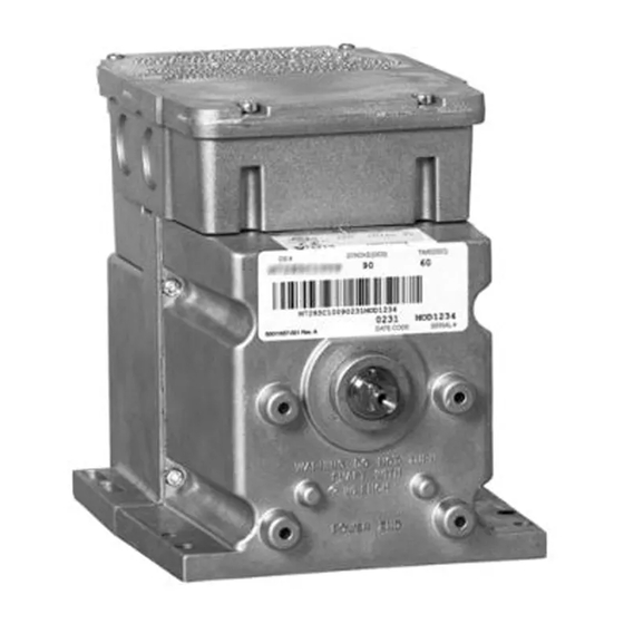
APPLICATION
The Series 41 and Series 81 Modutrol IV Motors are
2-position (line- and low- voltage, respectively) spring-return
motors. They are used to operate dampers or valves in
applications where it is necessary or desirable to have the
controlled element return to the starting position in the event
of power failure or interruption.
® U.S. Registered Trademark
Copyright © 2000 Honeywell • All Rights Reserved
Series 41 and 81
Modutrol IV™ Motors
FEATURES
• Used to replace M445, M845 and M865 motors.
• Models rated for 25 lb.-in. or 60 lb.-in. torque.
• Integral spring return returns motor to normal position
(open or closed) when power is interrupted.
• Oil immersed motor and gear train for reliable
performance and long life.
• Wiring box provides NEMA 3 weather protection.
• Motor operates from 24 Vac. Models are available
with factory installed transformer, or an internal
transformer can be field added.
• Quick-connect terminals are standard-screw terminal
adapter is available.
• Adapter bracket for matching shaft height of older
motors is standard with TRADELINE motors.
• TRADELINE motors have field adjustable stroke
(90° to 160°).
• Die-cast aluminum housing.
• Motors are designed for either normally open or
normally closed valves and dampers.
• Integral auxiliary switches are available factory
mounted, or can be field added to TRADELINE models.
• TRADELINE motors may operate valve linkages from
the power end or auxiliary end shafts for normally
closed or normally open valve applications.
Application ........................................................................
Features ...........................................................................
Specifications ...................................................................
Ordering Information ........................................................
Installation ........................................................................
Settings and Adjustments .................................................
Operation and Checkout .................................................. 10
Replacement .................................................................... 11
PRODUCT DATA
Contents
1
1
2
2
4
7
63-2187-3
Table of Contents

Related Manuals for Honeywell Modutrol IV Motors 41


Summary of Contents for Honeywell Modutrol IV Motors 41
-
Page 1: Table Of Contents
APPLICATION The Series 41 and Series 81 Modutrol IV Motors are 2-position (line- and low- voltage, respectively) spring-return motors. They are used to operate dampers or valves in applications where it is necessary or desirable to have the controlled element return to the starting position in the event of power failure or interruption. -
Page 2: Specifications
SERIES 41 AND 81 MODUTROL IV™ MOTORS SPECIFICATIONS Models: TRADELINE models are selected and packaged to provide ease of stocking, ease of handling and maximum replacement value. TRADELINE model specifications are the same as those of standard models unless specified otherwise. TRADELINE models have auxiliary switch cams. - Page 3 TOP VIEW 4-1/16 (103) AUXILARY 9/16 (15) ADAPTER BRACKET Fig. 1. Series 41 and Series 81 Modutrol IV Motor mounting dimensions in in. (mm). Dead Weight Load On Shaft (maximum): Power or Auxiliary End: 200 lb. [90.8 kg]. Combined Load: 300 lb. [136 kg]. (Dual-stroke motors only.) Maximum Damper Rating [B Dimension]: 25 lb.-in.
-
Page 4: Installation
SERIES 41 AND 81 MODUTROL IV™ MOTORS Accessories (continued): 4074EZE Bag Assembly with parts to provide CE compliance. 7617ADW Crank Arm approximately 0.75 in. shorter than 7616BR Crank Arm. Can rotate through downward position and clear motor base without requiring adapter bracket. ES650-117 Explosion-Proof Housing encloses motor for use in explosive atmospheres. - Page 5 Mounting Use the following guidelines for proper motor mounting: • Always install motors with the crankshaft horizontal. • Mounting flanges extending from motor housing base are drilled for 6.4 mm machine screws or bolts. • Motors are shipped from the factory in their normal position: —...
- Page 6 All wiring must agree with applicable codes, ordinances and regulations. Make sure that the voltage and frequency stamped on the motor correspond to the power supply characteristics. Fig. 5 shows the motor terminals (quick-connects located on top of the printed circuit board). Wiring compartment access is gained by removing the four screws from the wiring box top and lifting off the cover.
-
Page 7: Settings And Adjustments
POWER SUPPLY. PROVIDE DISCONNECT MEANS AND OVERLOAD PROTECTION AS REQUIRED. Fig. 6. Typical connections for Series 41 Motors. MOTOR THERMOSTAT LIMIT CONTROL 1 POWER SUPPLY. PROVIDE DISCONNECT MEANS AND OVERLOAD PROTECTION AS REQUIRED. Fig. 7. Typical connections for Series 81 Motors. MOTOR STARTER BLOWER POWER SUPPLY. - Page 8 BLUE LEAD YELLOW LEAD RED LEAD USE NEC CLASS 1 WIRING UNLESS POWER SUPPLY MEETS CLASS 2 REQUIREMENTS. TAPE UNUSED LEADS. ENSURE THE CURRENT DRAW OF THE EXTERNAL CIRCUIT IS LESS THAN SWITCH CONTACT RATING.
- Page 9 CAUTION Equipment Damage Hazard. Can damage the motor beyond repair. Never turn the motor shaft by hand or with a wrench. Forcibly turning the motor shaft damages the gear train and stroke limit contacts. NOTES: — Auxiliary switches can only be added to motors that include auxiliary switch cams.
-
Page 10: Operation And Checkout
SERIES 41 AND 81 MODUTROL IV™ MOTORS MOVE SCREWDRIVER AT TOP ONLY TO ADJUST CAM. 1/8 INCH STRAIGHT-BLADE SCREWDRIVER SLOW RISE PORTION (APPROX. 10 DIFF.) AUXILIARY LEFT/OUTER AUXILIARY SWITCH OUTER FAST RISE AUXILIARY PORTION (APPROX. (RED) 1 DIFF.) MOTOR OPEN POWER OPERATION AND CHECKOUT Operation... -
Page 11: Replacement
Valve Application 1. Check entire motorized valve assembly to ensure that the mechanical connections (among motor, linkage, and valve) are proper and secure. Be certain that the linkage is adjusted according to the linkage instructions. Leave the linkage cover off until the checkout is completed. 2. - Page 12 Home and Building Control Home and Building Control Honeywell Honeywell Limited-Honeywell Limitée 1985 Douglas Drive North 35 Dynamic Drive Golden Valley, MN 55422 Scarborough, Ontario M1V 4Z9 63-2187—3 B.B. Rev. 10-00 Honeywell Asia Pacific Inc. Honeywell Europe S.A. Room 3213-3225 3 Avenue du Bourget Sun Hung Kai Centre 1140 Brussels...