Table of Contents
Quick Links
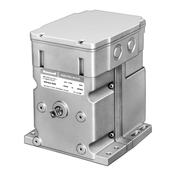
APPLICATION
The Series 61 and Series 62 Modutrol IV™ Motors are
three-wire spring return and non-spring return floating control
motors. Use these motors with controllers that provide a
switched spdt or floating output to operate dampers or valves.
The Series 62 motors also have an internal electrically
isolated feedback potentiometer that provides indication of
the motor shaft position and can be used for slaving Series 90
Motors or rebalancing an external control circuit.
® U.S. Registered Trademark
Copyright © 2000 Honeywell • All Rights Reserved
Series 61 and Series 62
Modutrol IV™ Motors
FEATURES
• Directly replaces M644, M944B,E,G,H,J,K,R,S and
M945B,C,G,K,L,AD Motors.
• Oil-immersed motor and gear train for reliable
performance and long life.
• Junction box provides NEMA 3 weather protection.
• Motor and circuitry operate from 24 Vac. Models
available with factory-installed transformer, or a
field-added internal transformer.
• Quick-connect terminals standard screw terminal
adapter available.
• Adapter bracket for matching shaft height of older
motors standard with replacement motors.
• Field-adjustable stroke (90° to 160°) models available.
• Nominal standard timing of 30 seconds for 90° stroke
and 60 seconds for 160° stroke. Other timings available.
• Die-cast aluminum housing.
• Integral auxiliary switches available factory mounted,
or can be field added to TRADELINE® models.
• Integral spring returns motor shaft to normal position
(fully open or fully closed, depending on model) upon
power interruption.
• Series 62 models include electrically isolated feedback
potentiometer that provides shaft position indication.
• Series 62 TRADELINE models have linear feedback,
configurable for slaving Series 90 Motors.
• Spring return motors can operate valve linkages from
power end or auxiliary end shafts for normally closed
or normally open valve applications.
Application ........................................................................
Features ...........................................................................
Specifications ...................................................................
Ordering Information ........................................................
Installation ........................................................................
Settings and Adjustments .................................................
Operation .......................................................................... 12
Checkout .......................................................................... 12
Replacement .................................................................... 12
PRODUCT DATA
Contents
1
1
2
2
5
8
63-2188-4
Table of Contents

Related Manuals for Honeywell Modutrol IV Series 61


Summary of Contents for Honeywell Modutrol IV Series 61
-
Page 1: Table Of Contents
Contents Application ................ Features ................Specifications ..............Ordering Information ............Installation ................ Settings and Adjustments ..........Operation ................12 Checkout ................12 Replacement ..............12 ® U.S. Registered Trademark Copyright © 2000 Honeywell • All Rights Reserved 63-2188-4... -
Page 2: Specifications
Honeywell, 1885 Douglas Drive North Minneapolis, Minnesota 55422-4386 In Canada—Honeywell Limited/Honeywell Limitée, 35 Dynamic Drive, Scarborough, Ontario M1V 4Z9. International Sales and Service Offices in all principal cities of the world. Manufacturing in Australia, Canada, Finland, France, Germany, Japan, Mexico, Netherlands, Spain, Taiwan, United Kingdom, U.S.A. - Page 3 SERIES 61 AND SERIES 62 MODUTROL IV™ MOTORS TOP VIEW TOP VIEW OF BRACKET 4-7/8 4-1/4 (124) (107) 4-5/8 5-13/16 (116) (148) 5-1/2 2-5/16 (140) (58) 11/16 (17) POWER END 13/16 (20) 1/4 (7) 4-1/16 (103) 1-1/2 (37) 4-7/8 (124) 4-1/16 (103) 5-9/16 (141) 4-1/16 (103)
- Page 4 O-Z/Gedney, Nelson Enclosures and Controls Timing And Torque: See Table 4. P.O. Box 471650 Tulsa, OK 74147-1650 Approvals: (Requires Honeywell 7617DM Coupling.) ® Underwriters Laboratories Inc. Listed: File No. E4436, Guide Q100 Linkage connects Modutrol Motor to V51 Butterfly No. XAPX.
-
Page 5: Installation
SERIES 61 AND SERIES 62 MODUTROL IV™ MOTORS INSTALLATION • Spring Return Motors are shipped from the factory in their normal position. • Normally closed models are shipped at the limit of When Installing this Product... counterclockwise rotation, as viewed from the power end of the motor. - Page 6 SERIES 61 AND SERIES 62 MODUTROL IV™ MOTORS STANDARD BOLTS (4) BOLTS PROVIDED (4) WIRING MOTOR ADAPTER BRACKET EQUIPMENT BASE 1 #12 OR 1/4" ZINC PLATED MACHINE SCREWS OR BOLTS SPRING RETURN NON-SPRING RETURN M452E Fig. 3. Mounting the motor with an adapter bracket. Valve Linkages For valve linkage applications (other than the Q5001): 1.
- Page 7 SERIES 61 AND SERIES 62 MODUTROL IV™ MOTORS WIRING POWER MOTOR END OF MOTOR Q5001 VALVE LINKAGE 1/4-20 UNC 1 in. LONG MOUNTING BOLTS VALVE M17092 Fig. 4. Mounting the motor on a Q5001 Valve Linkage. Wiring ADJUSTABLE STROKE POTENTIOMETER STROKE CAUTION ADJUSTMENT...
-
Page 8: Settings And Adjustments
MOTOR CONTROLLER When replacing a motor that was connected to an R927C or R9107A Relay, Honeywell recommends performing a retrofit to remove the relay and the old motor. Replace both with one Series 90 Modutrol IV motor (that is, do not replace the relay). - Page 9 SERIES 61 AND SERIES 62 MODUTROL IV™ MOTORS Setting Stroke at 90° or 160° 3. Insert 1/8 in. screwdriver blade into a slot on inner cam and move the screwdriver top as far as possible 1. Adjust the trim potentiometer: clockwise (viewed from the power end).
- Page 10 SERIES 61 AND SERIES 62 MODUTROL IV™ MOTORS Table 5. Shunt Resistor Selections. Linear Slaving Series 90 Stroke Feedback W902 Control Motor 90° None Green (174 ohms) Purple (274 ohms) 160° None White (143 ohms) Red (187 ohms) Note that the W902 Control is obsolete, replaced by the W964F, which does not require a feedback signal.
- Page 11 SERIES 61 AND SERIES 62 MODUTROL IV™ MOTORS Auxiliary Switch Adjustment 4. Once motor reaches correct position, disconnect the jumper. 5. For a switch differential of 1°, check continuity of auxiliary IMPORTANT switch contacts R-B and rotate the cam as follows: When adjusting the auxiliary switch cams use the a.
-
Page 12: Operation
Valve applications with a Q5001 Linkage do not varies. See Table 6. require the 220738A Adapter Bracket. To operate Honeywell • The auxiliary switch, if used, operates at the desired point V5011 Two-way or V5013 Three-way Valves through full of motor rotation.