Table of Contents
- 1 Table of Contents
- 2 Warning Decal Placement
- 3 Important Precautions
- 4 Before You Begin
- 5 Part Identification Chart
- 6 Assembly
- 7 Operation and Adjustment
- 8 How to Fold and Move the Treadmill
- 9 Troubleshooting
- 10 Exercise Guidelines
- 11 Part List
- 12 Exploded Drawing
- 13 Ordering Replacement Parts
- 14 Limited Warranty
www.healthrider.com
Model No. HRTL24912.0
Serial No.
USER'S MANUAL
Write the serial number in the space
above for reference.
Serial Number
Decal
QUESTIONS?
If you have questions, or if parts
are damaged or missing, DO NOT
CONTACT THE STORE; please
contact Customer Care.
IMPORTANT: Please register this
product (see the limited warranty
on the back cover of this manual)
before contacting Customer Care.
CALL TOLL-FREE:
1-888-922-4222
Mon.–Fri. 6 a.m.–6 p.m. MT
Sat. 8 a.m.–4 p.m. MT
ON THE WEB:
www.healthriderservice.com
CAUTION
Read all precautions and instruc-
tions in this manual before using
this equipment. Keep this manual
for future reference.
Table of Contents

Related Manuals for Healthrider H50 Crosswalk Sl Treadmill


Summary of Contents for Healthrider H50 Crosswalk Sl Treadmill
- Page 1 Model No. HRTL24912.0 Serial No. USER’S MANUAL Write the serial number in the space above for reference. Serial Number Decal QUESTIONS? If you have questions, or if parts are damaged or missing, DO NOT CONTACT THE STORE; please contact Customer Care.
-
Page 2: Table Of Contents
Apply the decal in the location shown. Note: The decal(s) may not be shown at actual size. HEALTHRIDER is a registered trademark of ICON IP, Inc. -
Page 3: Important Precautions
14. To purchase a surge suppressor, see your local 4. The treadmill is intended for home use only. HEALTHRIDER dealer, call the telephone Do not use the treadmill in any commercial, number on the front cover of this manual, or rental, or institutional setting. - Page 4 20. The heart rate monitor is not a medical 24. Do not change the incline of the treadmill by device. Various factors, including the user’s placing objects under the treadmill. movement, may affect the accuracy of heart rate readings. The heart rate monitor is 25.
-
Page 5: Before You Begin
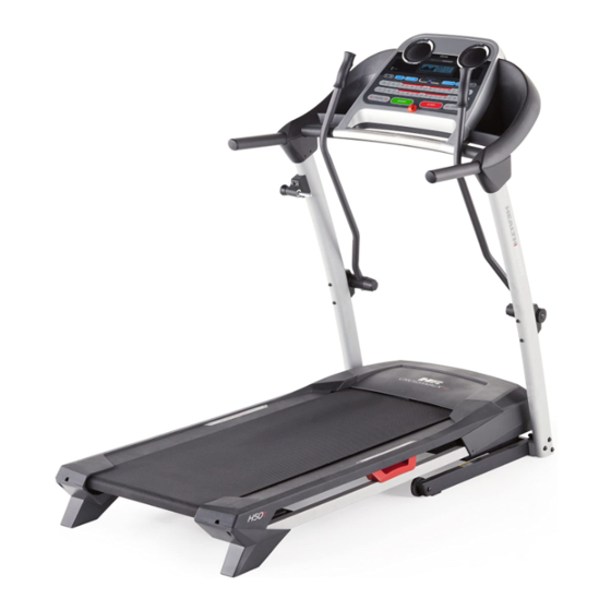
BEFORE YOU BEGIN Thank you for selecting the new HEALTHRIDER reading this manual, please see the back cover of this ® CROSSWALK SL treadmill. The H50 CROSSWALK SL manual. To help us assist you, note the product model treadmill provides an impressive selection of features number and serial number before contacting us. -
Page 6: Part Identification Chart
PART IDENTIFICATION CHART Use the drawings below to identify small parts used for assembly. The number in parentheses below each draw- ing is the key number of the part, from the PART LIST near the end of this manual. The number following the key number is the quantity used for assembly. -
Page 7: Assembly
ASSEMBLY • T o hire a service technician to assemble this • Left parts are marked “L” or “Left” and right parts product in your home, call 1-800-445-2480. are marked “R” or “Right.” • Assembly requires two persons. • To identify small parts, see page 6. • Place all parts in a cleared area and remove the • Assembly requires the following tools: packing materials. - Page 8 3. Identify the Right Upright (76). Have a second person hold the Right Upright near the Base (74). See the inset drawing. Tie the wire tie in the Right Upright (76) securely around the end of the Upright Wire (63). Then, insert the Upright Wire into the lower end of the Right Upright as you pull the other end of the wire tie through the Wire Tie...
- Page 9 5. Hold the Left Upright (66) against the Base (74). Insert a 3/8" x 3 1/4" Screw (2) with a 3/8" Star Washer (3) into the top hole in the Left Upright (66). Then, partially tighten the Screw into the Base (74).
- Page 10 7. Set the console assembly face down on a soft surface to avoid scratching the console. Loosen the four #8 x 1" Screws (7). Carefully pivot the Console Frame (61) to the position shown. Identify the Left and Right Accessory Trays (90, 60).
- Page 11 9. Have a second person hold the console assembly near the Right Upright (76). Console Assembly Connect the Upright Wire (63) to the console wire. See the inset drawing. The connectors should slide together easily and snap into place. If they do not, turn one connector and try again.
- Page 12 11. Slide the Right Upright Cover (89) up against the Right Handrail (64). Attach the Right Upright Cover with two M4.2 x 16mm Screws (56). Be careful not to overtighten the Screws. Attach the Left Upright Cover (not shown) as described above.
- Page 13 13. Attach the Latch Housing (67) with the Latch Spacer (44) to the Left Upright (66) with two #10 x 1 1/2" Screws (86); make sure that the knob is on the indicated side. Start both Screws, and then tighten them. Do not overtighten the Screws.
-
Page 14: Operation And Adjustment
OPERATION AND ADJUSTMENT HOW TO CONNECT THE POWER CORD nominal 120-volt circuit capable of carrying 15 or more amps. To avoid overloading the circuit, do Use a Surge Suppressor not plug other electrical devices, except for low- power devices such as cell phone chargers, into Your treadmill, like other electronic equipment, can be the surge suppressor or into an outlet on the same circuit. - Page 15 CONSOLE DIAGRAM Clip FEATURES OF THE CONSOLE trainer coaches you through every step of your work- out. To purchase iFit cards at any time, go to www.iFit.com or call the telephone number on the The treadmill console offers an impressive array of front cover of this manual.
- Page 16 HOW TO TURN ON THE POWER HOW TO USE THE MANUAL MODE IMPORTANT: If the treadmill has been exposed to 1. Insert the key into the console. cold temperatures, allow it to warm to room tem- perature before turning on the power. If you do not See HOW TO TURN ON THE POWER at the left.
- Page 17 5. Change the incline of the treadmill as desired. the distance that you have walked or run, the approximate number of calories that you have To change the incline of the treadmill, press the burned, or the speed of the walking belt. Press the Incline increase or decrease buttons or one of the Display button repeatedly until the upper display numbered Incline buttons.
- Page 18 HOW TO USE A CALORIE WORKOUT ment, a series of tones will sound. If a different Current Segment 1. Insert the key into the console. speed and/or incline set- ting is programmed for See HOW TO TURN ON THE POWER on page 16. the next segment, the speed and/or incline set- 2.
- Page 19 HOW TO USE A PERFORMANCE WORKOUT During the workout, the profile will show your Current Segment 1. Insert the key into the console. progress. The flashing segment of the profile See HOW TO TURN ON THE POWER on page 16. represents the current segment of the workout. 2. Select a performance workout. The height of the flashing segment indicates the To select a performance workout, press the...
- Page 20 HOW TO USE AN IFIT WORKOUT 3. Start the workout. To purchase iFit cards, go to www.iFit.com or call the Press the Start button or the Speed increase button telephone number on the front cover of this manual. to start the workout. A moment after you press the iFit cards are also available at select stores.
- Page 21 THE INFORMATION MODE power switch into the reset position, and insert the key The console features an information mode that keeps into the console. However, track of the total distance that the walking belt has when you remove the key, moved and the total number of hours that the treadmill the displays will remain lit, has been used.
-
Page 22: How To Fold And Move The Treadmill
HOW TO FOLD AND MOVE THE TREADMILL HOW TO FOLD THE TREADMILL HOW TO MOVE THE TREADMILL Before folding the treadmill, adjust the incline to Before moving the treadmill, fold it as described at the the lowest position. If you do not do this, you may left. -
Page 23: Troubleshooting
TROUBLESHOOTING Most treadmill problems can be solved by following c. Remove the key from the console, and then the simple steps below. Find the symptom that reinsert it. applies, and follow the steps listed. If further assis- tance is needed, see the front cover of this manual. d. - Page 24 Locate the Reed Switch (33) and the Magnet (32) b. If the walking belt is overtightened, treadmill per- on the right side of the Pulley (31). Turn the Pulley formance may decrease and the walking belt may until the Magnet is aligned with the Reed Switch. become damaged.
- Page 25 SYMPTOM: The walking belt is off-center or slips SYMPTOM: The upperbody arms squeak during when walked on a. If the walking belt is off-center, first remove the a. (Note: Correcting this symptom requires a small key and UNPLUG THE POWER CORD. If the amount of marine grease, available at hardware walking belt has shifted to the left, use the hex stores.) Turn the resistance knob (A) counterclock-...
-
Page 26: Exercise Guidelines
EXERCISE GUIDELINES Burning Fat—To burn fat effectively, you must exer- WARNING: cise at a low intensity level for a sustained period of Before beginning this time. During the first few minutes of exercise, your or any exercise program, consult your physi- body uses carbohydrate calories for energy. -
Page 27: Part List
PART LIST Model No. HRTL24912.0 R1012B Key No. Qty. Description Key No. Qty. Description #8 x 1/2" Ground Screw Lift Frame 3/8" x 3 1/4" Screw Belly Pan 3/8" Star Washer Power Cord Grommet #8 x 3/4" Screw Power Cord M8 x 25mm Screw Power Switch M8 Star Washer... -
Page 28: Exploded Drawing
EXPLODED DRAWING A Model No. HRTL24912.0 R1012B... - Page 29 EXPLODED DRAWING B Model No. HRTL24912.0 R1012B...
- Page 30 EXPLODED DRAWING C Model No. HRTL24912.0 R1012B 16 75...
- Page 31 EXPLODED DRAWING D Model No. HRTL24912.0 R1012B...
-
Page 32: Ordering Replacement Parts
ORDERING REPLACEMENT PARTS To order replacement parts, please see the front cover of this manual. To help us assist you, be prepared to pro- vide the following information when contacting us: • the model number and serial number of the product (see the front cover of this manual) • the name of the product (see the front cover of this manual) • the key number and description of the replacement part(s) (see the PART LIST and the EXPLODED DRAWING near the end of this manual)