Table of Contents
Quick Links
Table of Contents

Related Manuals for Toshiba e-STUDIO500P


Summary of Contents for Toshiba e-STUDIO500P
- Page 1 PRINTER e-STUDIO 500P P/N 12G9609...
- Page 2 Comments may be addressed to Toshiba America Business Solutions, 2 Musick, Irvine, CA 92618 -- Attn Service Training. Toshiba may use or distribute any of the information you supply in any way it believes appropriate without incurring any obligation to you. You can download copies of this manual from the Toshiba FYI website under Tech-To-Go.
-
Page 3: Table Of Contents
Table of contents Laser notices ............xi Safety information . - Page 4 Symptom tables ..............2-5 Base printer symptoms .
- Page 5 Signature button assembly service check ..........2-122 StapleSmart finisher service check .
- Page 6 Engine Setting 1 through 4 ........... . .3-20 Model Name .
- Page 7 202 Paper Jam Open Rear Door ..........3-39 23x Paper Jam Open Duplex Rear Door .
- Page 8 Operator panel board removal ............4-66 Operator panel buttons removal .
- Page 9 Assembly 17: Cabling diagrams 1 ........... . 7-34 Assembly 18: Cabling diagrams 2 .
- Page 10 Service Manual...
-
Page 11: Laser Notices
Laser notices Laser notice The printer is certified in the U.S. to conform to the requirements of DHHS 21 CFR Subchapter J for Class I (1) laser products, and elsewhere is certified as a Class I laser product conforming to the requirements of IEC 60825-1. - Page 12 Avvertenze sui prodotti laser Questa stampante è certificata negli Stati Uniti per essere conforme ai requisiti del DHHS 21 CFR Sottocapitolo J per i prodotti laser di classe 1 ed è certificata negli altri Paesi come prodotto laser di classe 1 conforme ai requisiti della norma CEI 60825-1.
- Page 13 Laserinformatie De printer voldoet aan de eisen die gesteld worden aan een laserprodukt van klasse I. Voor de Verenigde Staten zijn deze eisen vastgelegd in DHHS 21 CFR Subchapter J, voor andere landen in IEC 60825-1. Laserprodukten van klasse I worden niet als ongevaarlijk aangemerkt. De printer is voorzien van een laser van klasse IIIb (3b), dat wil zeggen een gallium arsenide-laser van 5 milliwatt met een golflengte van 770-795 nanometer.
- Page 14 Laser-notis Denna skrivare är i USA certifierad att motsvara kraven i DHHS 21 CFR, underparagraf J för laserprodukter av Klass I (1). I andra länder uppfyller skrivaren kraven för laserprodukter av Klass I enligt kraven i IEC 60825-1. Laserprodukter i Klass I anses ej hälsovådliga. Skrivaren har en inbyggd laser av Klass IIIb (3b) som består av en laserenhet av gallium-arsenid på...
- Page 15 Japanese Laser Notice Laser notices...
- Page 16 Korean Laser Notice Service Manual...
-
Page 17: Safety Information
Safety information • The safety of this product is based on testing and approvals of the original design and specific components. The manufacturer is not responsible for safety in the event of use of unauthorized replacement parts. • The maintenance information for this product has been prepared for use by a professional service person and is not intended to be used by others. - Page 18 Sicherheitshinweise • Die Sicherheit dieses Produkts basiert auf Tests und Zulassungen des ursprünglichen Modells und bestimmter Bauteile. Bei Verwendung nicht genehmigter Ersatzteile wird vom Hersteller keine Verantwortung oder Haftung für die Sicherheit übernommen. • Die Wartungsinformationen für dieses Produkt sind ausschließlich für die Verwendung durch einen Wartungsfachmann bestimmt.
- Page 19 Informació de Seguretat • La seguretat d'aquest producte es basa en l'avaluació i aprovació del disseny original i els components específics. El fabricant no es fa responsable de les qüestions de seguretat si s'utilitzen peces de recanvi no autoritzades. • La informació...
-
Page 20: Preface
Preface This manual contains maintenance procedures for service personnel. It is divided into the following chapters: General information contains a general description of the printer and the maintenance approach used to repair it. Special tools and test equipment are listed in this chapter, as well as general environmental and safety instructions. -
Page 21: 1. G Eneral Information
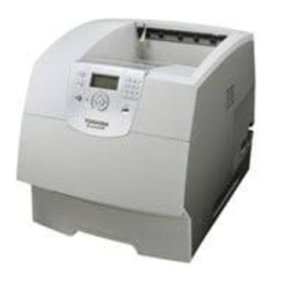
1. G eneral information T he e-S T UDIO 500P las er printers are letter quality page printers designed to attach to IB M-compatible pers onal computers and to most computer networks. T he e-S T UDIO 500l P is available is the following models : Model name C onfiguration e-S T UDIO 500P... -
Page 22: Configured Models
C onfigured model T he following illus tration s hows a s tandard network printer. S ervice Manual... -
Page 23: Specifications
Specifications Resolution • 1200 1200 dpi • 2400 Image Quality • 1200 Image Quality • 600 x 600 dpi Data streams • PostScript 3 emulation • PCL 6 emulation • • Print speed and performance print speed Performance Performance speed depends on: •... -
Page 24: Memory Configuration
Memory c onfiguration e-S T UDIO 500P Memory type S tandard DR AM (MB ) Optional memory (MB ) 128 and 512MB available (100 pin DDR S DR AM unbuffered DIMMs ) Maximum (MB ) Depending upon the options and features used, additional memory may be required to optimize performance. Available memory options Optional 128MB and 512MB S DR AM DIMMs are available from T os hiba. -
Page 25: Dimensions
Dimensions Description Height Width Depth Weight Printer e-STUDIO 500P 20.2 in. 16.0 i 17.2 in. 51.6 lb (406 mm) (436 mm) (513 mm) (23.1 kg) Options Duplex 500 page option 2.13 in 15.6 in 23.4 in 11 lb 500-Sheet drawer 5.3 in. -
Page 26: Power Requirements
Power requirements Average nominal power requirements for the base printer configuration (110 volt). Power levels are shown in watts (W). Maximum current is given in Amperes (A). Printing states e-STUDIO 500P Off (all models) .05 W .05 W .05 W Idle—average power Power Saver on 20 W... -
Page 27: Environment
Environment Printer temperature and humidity • Operating – Temperature: 16 to 32° C (60° to 90° F) – Relative humidity: 8 to 80% – Altitude: 10,000 ft. (0 to 3,048 meters) • Storage and shipping environment (packaged) – Temperature: -40° to 43° C (-40° to 110° F) –... -
Page 28: Media Specifications
Media s pecifications P aper and s pec ialty media guidelines P rint media is paper, car d s tock, trans par enc ies , labels , and en velopes . T his pr inter pr ov ides hi gh quality pr inting on a variety of pr int media. - Page 29 P rint media s izes (continued) P rint media Dimens ions s ize (UAT — univers ally indicates adjus table tray) s uppor t ) E xecutive 184.2 x 266.7 mm (7.25 x 10.5 in.) F olio 216 x 330 mm (8.5 x 13 in.) S tatement 139.7 x 215.9 mm...
- Page 30 P rint media s izes (c ontinued) P rint media Dimens ions s ize (UAT — univers ally ( X indicates adjus table tray) s upport) O ther 98.4 x 162 mm E nvelope1 to 176 x 250 mm (3.87 x 6.38 in. to 6.93 x 9.84 in.) 98.4 x 162 mm to 229 x 342 mm...
-
Page 31: Index
Print media weights Print media weight Multipurpose Integrated tray and Print media Type feeder Envelope 2000-Sheet optional feeder drawer 500-sheet drawer Paper Xerographic or 60 to 176 g/m grain 60 to 135 g/m grain 60 to 135 g/m business paper long (16 to 47 lb long (16 to 36 lb (16 to 36 lb... -
Page 32: Selecting Print Media
Selecting print media Selecting the appropriate print media for your printer helps you avoid printing problems. The following sections contain guidelines for choosing the correct print media for your printer. • Paper • Transparencies • Envelopes • Labels • Card stock Paper For the best print quality, use 75 g/m (20 lb) xerographic, grain long paper. -
Page 33: Labels
• For best performance and to minimize jams, do not use envelopes that: – Have excessive curl or twist. – Are stuck together or damaged in any way. – Contain windows, holes, perforations, cutouts or embossing. – Use metal clasps, string ties, or metal folding bars. –... -
Page 34: Card Stock
• Portrait orientation is preferred, especially when printing bar codes. • Do not use labels that have exposed adhesive. Card stock Card stock is single ply, and has a large array of properties, such as the moisture content, thickness, and texture, that can significantly affect print quality. -
Page 35: Avoiding Jams
Avoiding jams Use appropriate print media (paper, transparencies, labels, and card stock) to help ensure trouble-free printing. “Supported print media” on page 1-8 for more information. Note: Try a limited sample of any print media you are considering using with the printer before purchasing large quantities. -
Page 36: Acronyms
Acronyms BLDC Brushless DC motor Customer Replaceable Unit Customer setup DIMM Dual Inline Memory Module DRAM Dynamic Random Access Memory Digital multimeter Enhanced Data Out EEPROM Electrically Erasable Programable Read-Only Memory Electrophotographic process EPROM Erasable Programmable Read-Only Memory Electrostatic Discharge Field Replaceable Unit Gigabyte HCIT... -
Page 37: Envelopes
2. Diagnostic information Start CAUTION: Remove the power cord from the printer or wall outlet before you connect or disconnect any cable or electronic board or assembly for personal safety and to prevent damage to the printer. Use the handholds on the side of the printer. Make sure your fingers are not under the printer when you lift or set the printer down. -
Page 38: Understanding The Printer Operator Panel
Understanding the printer operator panel The operator panel on your printer is a 4-line back-lit gray scale display that can show both graphics and text. The Back, Menu, and Stop buttons are located to the left of the display, the navigation buttons are located below the display, and the numeric pad is located to the right of the display. -
Page 39: Understanding The Menus
Operator panel (continued) Button Function Numeric pad The numeric pad consists of numbers, a pound '#' sign, and a backspace button. The 5 button has a raised bump for non-visual orientation. The numbers are used to enter numeric values for items like quantities or PINs. The backspace is used to delete the number to the left of the cursor. -
Page 40: Power-On Self Test (Post) Sequence
Power-On Self Test (POST) sequence When you turn the printer on, it performs a Power-On Self Test. Check for correct POST functioning of the base printer by observing the following: The LED turns comes on. The operator panel turns on. A partial row of pixels are displayed. -
Page 41: Symptom Tables
Symptom tables Base printer symptoms Symptom Action Dead machine Go to “Dead machine service check” on page 2-80. Operator panel—one or more buttons do Go to “One or more operator panel buttons fail” on not work. page 2-106. Operator panel—none of the buttons work. Go to “No buttons work”... -
Page 42: Paper Tray Symptoms
Paper tray symptoms Symptom Action Paper feed problem with 250-Sheet Paper Go to “Input tray(s) service check” on page 2-102. Tray. Paper feed problem with 500-Sheet Paper Go to “Input tray(s) service check” on page 2-102. Tray. Media fails to pass through from the lower Go to “Input tray(s) service check”... -
Page 43: Diagnostic Information
Diagnostic information... -
Page 44: Service Error Codes
Messages and error codes Service error codes Service error codes are generally non-recoverable except in an intermittent condition when you can POR the printer to temporarily recover from the error condition. Service error codes (9xx.xx) Error Display text Description Action code codes RIP Software... - Page 45 Service error codes (9xx.xx) (continued) Error Display text Description Action code codes Hot roll took too long to • Bad thermistor, circuit or cabling. Go to “920.xx—Cold fuser heat up after service check” on page 2-87. • Fuser not receiving sufficient AC transitioning to new power.
- Page 46 Service error codes (9xx.xx) (continued) Error Display text Description Action code codes Hot roll fell too far below • Bad thermistor, circuit, or cabling. Go to “920.xx—Cold fuser the desired temperature service check” on page 2-87. • Noisy thermistor signal. while printing.
- Page 47 Service error codes (9xx.xx) (continued) Error Display text Description Action code codes Hot roll fell too far below • Bad thermistor, circuit, or cabling. Go to “920.xx—Cold fuser the desired temperature service check” on page 2-87. • Noisy thermistor signal. while printing.
- Page 48 Service error codes (9xx.xx) (continued) Error Display text Description Action code codes Hot roll fell too far below • Bad thermistor, circuit, or cabling. Go to “920.xx—Cold fuser desired temperature service check” on page 2-87. • Noisy thermistor signal. while printing. Fuser •...
- Page 49 Service error codes (9xx.xx) (continued) Error Display text Description Action code codes Hot roll fell too far below • Bad thermistor, circuit, or cabling. Go to “920.xx—Cold fuser the desired temperature service check” on page 2-87. • Noisy thermistor signal. while printing.
- Page 50 Service error codes (9xx.xx) (continued) Error Display text Description Action code codes Hot roll fell too far below • Bad thermistor, circuit, or cabling. Go to “920.xx—Cold fuser desired temperature service check” on page 2-87. • Noisy thermistor signal. while printing. Fuser •...
- Page 51 Service error codes (9xx.xx) (continued) Error Display text Description Action code codes Hot roll fell too far below • Bad thermistor, circuit, or cabling. Go to “920.xx—Cold fuser desired temperature service check” on page 2-87. • Noisy thermistor signal. while printing. Fuser •...
- Page 52 Service error codes (9xx.xx) (continued) Error Display text Description Action code codes Hot roll reached final • Low wattage or incorrect lamp. Go to “922.xx—Cold fuser lamp detection check” on page 2-89. • Bad thermistor, circuit, or cabling. temperature but took •...
- Page 53 Service error codes (9xx.xx) (continued) Error Display text Description Action code codes Hot roll did not reach • Low wattage or incorrect lamp. Go to “922.xx—Cold fuser operating temperature in check” on page 2-89. • Bad thermistor, circuit, or cabling. time (new enhanced •...
- Page 54 Service error codes (9xx.xx) (continued) Error Display text Description Action code codes Hot roll took too long to • Low wattage or incorrect lamp. Go to “922.xx—Cold fuser reach the beginning check” on page 2-89. • Bad thermistor, circuit, or cabling. lamp detection •...
- Page 55 Service error codes (9xx.xx) (continued) Error Display text Description Action code codes Hot roll timed out in • Low wattage or incorrect lamp. Go to “922.xx—Cold fuser trying to reach the final check” on page 2-89. • Bad thermistor, circuit, or cabling. lamp detection •...
- Page 56 Service error codes (9xx.xx) (continued) Error Display text Description Action code codes Hot roll did not reach • Low wattage or incorrect lamp. Go to “922.xx—Cold fuser operating temperature in check” on page 2-89. • Bad thermistor, circuit, or cabling. time (new enhanced •...
- Page 57 Service error codes (9xx.xx) (continued) Error Display text Description Action code codes Fuser over temperature. • Short in the thermistor circuit. Go to “923.xx—Hot fuser Fuser page count service check” on page 2-90. • Noisy thermistor signal between 0 and 99,999. •...
- Page 58 Service error codes (9xx.xx) (continued) Error Display text Description Action code codes Open thermistor check • Noisy thermistor signal. Go to “924.xx—Hot fuser failure. Fuser page service check” on page 2-91. • Intermittent connection. count between 400,000 • Thermistor cable not connected or and 499,999.
- Page 59 Service error codes (9xx.xx) (continued) Error Display text Description Action code codes Too hot to do lamp Attempting to POR machine after Go to “925.xx—Hot fuser detection and NVRAM receiving a 925.01. service check” on page 2-91. bit indicates previous wrong lamp detected.
- Page 60 Service error codes (9xx.xx) (continued) Error Display text Description Action code codes Cartridge fan stalled. • Loose connector. Go to “Cartridge fan service check” on page 2-76. • External blockage of the fan, preventing it from turning. • Bad fan. Main fan took too long to •...
- Page 61 Service error codes (9xx.xx) (continued) Error Display text Description Action code codes Mirror moor not up to • Check printhead Go to “Printhead service speed check” on page 2-122. • Check system board No hall effect detected • Check cable connections Go to “Main drive service at motor start.
- Page 62 Service error codes (9xx.xx) (continued) Error Display text Description Action code codes Overspeed detected • Faulty motor sensor Go to “Main drive service during speed control. check” on page 2-105. • Faulty system board Motor is type 0. Overspeed detected •...
- Page 63 Service error codes (9xx.xx) (continued) Error Display text Description Action code codes Delay line calibration System board Replace the system board. See failure “System board and inner shield removal” on page 4-76. NVRAM mismatch Go to “950.00 through 950.29 EPROM mismatch failure” on page 2-77.
- Page 64 Service error codes (9xx.xx) (continued) Error Display text Description Action code codes Replace the operator panel board or upper front cover. See “Upper front cover removal” on page 4-11 “Upper front cover removal” on page 4-11. Warning: When replacing any one of the following components: •...
- Page 65 Service error codes (9xx.xx) (continued) Error Display text Description Action code codes Replace the interconnect card. “Interconnect card assembly removal” on page 4-53. Warning: When replacing any one of the following components: • Operator panel assembly (or upper front cover) •...
-
Page 66
Service error codes (9xx.xx) (continued) Error Display text Description Action code codes Unreliable comma to The engine is experiencing unreliable Service errors 980 thru 984 Paperport device communications to the specified device.
can be one of the following: system board, duplex, tray x (1, 2, 3, 4, or 5), envelope Interface protocol The engine protocol violation detected by... -
Page 67: User Status Displays
User status displays Warning messages (second lines) These second line warnings apply to the user status displays (see “User status displays” on page 2-31). For example, ReadyIf none of the conditions exist that are listed in the following table, line two is blank. If any of the messages in the table are displayed, the following actions can be taken: •... -
Page 68: User Attendance Messages
User attendance messages User attendance messages Error Primary message Description/action code code Change Cartridge Select one of the following actions: Invalid Refill • Remove the toner cartridge and install a new cartridge. • Press and hold and press to display debug data for the engine and cartridge code. - Page 69 User attendance messages (continued) Error Primary message Description/action code code Check Duplex This messages displays for the following conditions: Connection • The duplex option may have been removed from the printer, possibly to clear a paper jam or to remove the option. •...
- Page 70 User attendance messages (continued) Error Primary message Description/action code code Disk Corrupted The printer has detected there are errors on the hard disk that cannot be Reformat? corrected. The disk cannot be used until it is reformatted. Warning: All data on the disk will be lost if you format the disk. The following actions can be taken: •...
-
Page 71
User attendance messages (continued) Error Primary message Description/action code code Insert
=Tray 1, Tray 2, Tray 3, Tray 4, or Tray 5. The printer detects a tray needs to be inserted. The printer does not continue until it detects the tray is inserted. Note: This situation usually occurs when the tray is refilled during a job. - Page 72 User attendance messages (continued) Error Primary message Description/action code code Install Env Feed This message is displayed when the envelope feeder has been hot or Cancel Job unplugged. The printer requires the reinstallation of the feeder to print a page which has been formatted by the interpreter before the feeder was removed.
- Page 73 User attendance messages (continued) Error Primary message Description/action code code Reattach Bins x–y=Bins 1 to 5, Bins 2 to 6, or Bins 6 to 10 Bins x–y This messages displays for the following conditions: • The specified output bins may have been removed from the printer, possibly to clear a paper jam or to remove the option.
- Page 74 User attendance messages (continued) Error Primary message Description/action code code Defective Print Cartridge Error code 31 displays when the top front cover is closed and a defective print cartridge is detected. It may take the printer 10-20 seconds to determine if the print cartridge is defective. Depending on the setting of the Machine Class ID the printer may be allowed to print pages during this 10-20 second interval.
- Page 75 User attendance messages (continued) Error Primary message Description/action code code Insufficient Memory This message displays when the printer memory used to restore the Print and Hold jobs from the disk and found that some or all of the jobs could not be restored.
- Page 76 User attendance messages (continued) Error Primary message Description/action code code Flash Full This message displays when there is not enough free space in the flash memory to hold the resources that have been requested to be written to flash. Unformatted Flash This message displays when the printer detects an unformatted flash at power on.
- Page 77 User attendance messages (continued) Error Primary message Description/action code code Standard Parallel Port This error is displayed when data is sent to the printer across the parallel Disabled port, but the parallel port has been disabled. Once this message is displayed, reporting of further errors is suppressed until the menus are entered, or the printer is reset.
- Page 78 User attendance messages (continued) Error Primary message Description/action code code Incompatible Tray x An incompatible tray is installed. For Tray x, x= 2, 3, 4, or 5. Remove the incompatible tray and press to clear the message. Note: If the user installed the incompatible device to satisfy a Check Device Connections/reattach message, the user should reinstall an associated compatible option or hot unplug the option.
-
Page 79: User Line 2 Link Messages
User line 2 link messages If the printer is locked on a particular link, the link indication displays. If the printer is ready to process any link, no messages display. Link messages are listed in the following table. User message Explanation Parallel Standard Parallel Port, if available. -
Page 80: User Attendance Messages-Paper Jams And Paper Handling Errors (2Xx.xx)
User attendance messages—paper jams and paper handling errors (2xx.xx) When the printer jams, the appropriate jam message will be displayed on the printer operator panel. If you select Show Areas on the operator panel, you can view one or more images to help you clear the jam. 23... - Page 81 User attendance messages—paper jams and paper handling errors (2xx.xx) Error Description Possible causes Action code codes Input sensor covered too • Paper pre-staged in path. • Check MPF and friction pad. quickly • Bouncy input sensor. • Fan media and stack flat in tray or MPF.
- Page 82 User attendance messages—paper jams and paper handling errors (2xx.xx) Error Description Possible causes Action code codes Page did not reach exit • Page jammed on fuser input guide. • Check fuser entry guide for sensor. Fuser page toner build up. •...
- Page 83 User attendance messages—paper jams and paper handling errors (2xx.xx) Error Description Possible causes Action code codes Page did not reach exit • Page jammed on fuser input guide. • Check fuser entry guide for sensor. Fuser page toner build up. •...
- Page 84 User attendance messages—paper jams and paper handling errors (2xx.xx) Error Description Possible causes Action code codes Page did not reach exit • Page jammed on fuser input guide. • Check fuser entry guide for sensor. Fuser page toner build up. •...
- Page 85 User attendance messages—paper jams and paper handling errors (2xx.xx) Error Description Possible causes Action code codes Page did not reach exit • Page jammed on fuser input guide. • Check the fuser entry guide sensor. Fuser page for toner build up. •...
- Page 86 User attendance messages—paper jams and paper handling errors (2xx.xx) Error Description Possible causes Action code codes Page did not reach exit • Page jammed on fuser input guide. • Check the fuser entry guide sensor. Fuser page for toner build up. •...
- Page 87 User attendance messages—paper jams and paper handling errors (2xx.xx) Error Description Possible causes Action code codes Page did not reach exit • Page jammed on fuser input guide. • Check the fuser entry guide sensor. Fuser page for toner build up. •...
- Page 88 User attendance messages—paper jams and paper handling errors (2xx.xx) Error Description Possible causes Action code codes Page did not reach exit • Page jammed on fuser input guide. • Check the fuser entry guide sensor. Fuser page for toner build up. •...
- Page 89 User attendance messages—paper jams and paper handling errors (2xx.xx) Error Description Possible causes Action code codes Paper jam at fuser exit Page may be jammed in fuser exit or • Make sure the redrive door or redrive area. Fuser redrive area. is complete closed.
- Page 90 User attendance messages—paper jams and paper handling errors (2xx.xx) Error Description Possible causes Action code codes Exit sensor covered too Page may be jammed in fuser exit or • Make sure the redrive door long. Fuser page count redrive area. is complete closed.
- Page 91 User attendance messages—paper jams and paper handling errors (2xx.xx) Error Description Possible causes Action code codes Paper jam around fuser Page may be jammed in fuser exit or • Make sure the redrive door or redrive area. Fuser redrive area. is complete closed.
- Page 92 User attendance messages—paper jams and paper handling errors (2xx.xx) Error Description Possible causes Action code codes Exit sensor covered too Page may be jammed in fuser exit or • Make sure the redrive door long. Fuser page count redrive area. is complete closed.
- Page 93 User attendance messages—paper jams and paper handling errors (2xx.xx) Error Description Possible causes Action code codes Paper jam around fuser Paper may be jammed in fuser exit or • Make sure the redrive door exit or redrive area. redrive area. is complete closed.
- Page 94 User attendance messages—paper jams and paper handling errors (2xx.xx) Error Description Possible causes Action code codes Exit sensor covered too Page may be jammed in fuser exit or • Make sure the redrive door long. Fuser page count redrive area. is complete closed.
- Page 95 User attendance messages—paper jams and paper handling errors (2xx.xx) Error Description Possible causes Action code codes Paper jam around the Page may be jammed in fuser exit or • Make sure the redrive door fuser exit or redrive redrive area. is complete closed.
- Page 96 User attendance messages—paper jams and paper handling errors (2xx.xx) Error Description Possible causes Action code codes Exit sensor covered too Page may be jammed in fuser exit or • Make sure the redrive door long. Fuser page count redrive area. is complete closed.
- Page 97 User attendance messages—paper jams and paper handling errors (2xx.xx) Error Description Possible causes Action code codes Paper jam around the Page may be jammed in fuser exit or • Make sure the redrive door fuser exit or redrive redrive. is complete closed. area.
- Page 98 User attendance messages—paper jams and paper handling errors (2xx.xx) Error Description Possible causes Action code codes Exit sensor covered too Page may be jammed in fuser exit or • Make sure the redrive door long. Fuser page count redrive area. is complete closed.
- Page 99 User attendance messages—paper jams and paper handling errors (2xx.xx) Error Description Possible causes Action code codes Paper jam around the Page may be jammed in the fuser exit or • Make sure the redrive door fuser exit or redrive redrive area. is complete closed.
- Page 100 User attendance messages—paper jams and paper handling errors (2xx.xx) Error Description Possible causes Action code codes Exit sensor covered too Page may be jammed in fuser exit or • Make sure the redrive door long. Fuser page count redrive area. is complete closed.
- Page 101 User attendance messages—paper jams and paper handling errors (2xx.xx) Error Description Possible causes Action code codes Paper jam around the Page may be jammed in fuser exit or • Make sure the redrive door exit or redrive area. redrive area. is complete closed.
- Page 102 User attendance messages—paper jams and paper handling errors (2xx.xx) Error Description Possible causes Action code codes Exit sensor covered too Page may be jammed in the fuser exit or • Make sure the redrive door long. Fuser page count redrive area. is complete closed.
- Page 103 User attendance messages—paper jams and paper handling errors (2xx.xx) Error Description Possible causes Action code codes Paper did not arrive at • Duplex rear door not fully latched. • Make sure the duplex the duplex input sensor assembly rear door is •...
- Page 104 User attendance messages—paper jams and paper handling errors (2xx.xx) Error Description Possible causes Action code codes 235. Paper reached the Double feed separated in duplex. • Remove the two sheets duplex exit sensor but from the duplex option and another sheet is still see if the duplex fails again.
- Page 105 User attendance messages—paper jams and paper handling errors (2xx.xx) Error Description Possible causes Action code codes Paper is covering one of • Media left in the duplex and • Remove any sheets from Continue selected. the duplex sensors the duplex option. during a reset.
- Page 106 User attendance messages—paper jams and paper handling errors (2xx.xx) Error Description Possible causes Action code codes Duplex doublefeed, • Media left in the duplex and • Remove any sheets from Continue selected. input, and exit sensors the duplex option. are covered. •...
- Page 107 User attendance messages—paper jams and paper handling errors (2xx.xx) Error Description Possible causes Action code codes Page was not properly Failure to feed possible causes include: Fan media. picked from tray 1. • Edge locking Turn media over. • Worn or contaminated pick tires Reduce amount of media loaded in tray 1.
-
Page 108: Service Checks
Service checks Anytime the system board is replaced, the Configuration ID must be reset in NVRAM. Go to “Configuration ID” on page 3-21. Review the following information before performing any service checks. • Paper feed problems (especially paper jams): Go to “Display Log”... - Page 109 271.xx Paper Jam—Check Bin 1 displays Action Bottom pass thru sensor Check the flag for correct operation, binding, broken parts, or flag assembly interference from the sensor cable. If incorrect, repair as necessary. If correct, make sure the bottom pass thru sensor is correctly Control board connected to J5 on the control board.
- Page 110 Ready—Bin x Full displays and paper feeds into bin x Action Bin x sensor Check the sensor flag for binds. Make sure the sensor flag is not in Bin x sensor control board an up position. If the sensor flag is operating correctly, replace the bin x sensor.
-
Page 111: 900.Xx Error Code Service Check
900.xx Error code service check Action Printer POR Turn the printer off and on several times. If Error Code 900 continues to display, go to step 2. System board Turn the machine off and on several times, waiting a few minutes between power on and power off. -
Page 112: 927.Xx Fan Service Check
927.xx Fan service check 927.xx can be used for the main fan or the cartridge fan. • Main fan—927.00, 927.01, and 927.03 through 927.07. • Cartridge fan—927.02 Main fan Service tip: The main fan runs at full speed at the end of POR or when the printer is printing. It will only run half speed when the printer is in the Ready state and not printing. -
Page 113: 950.00 Through 950.29 Eprom Mismatch Failure
950.00 through 950.29 EPROM mismatch failure Warning: When replacing any one of the following components: • Operator panel assembly (or upper front cover) • System board assembly • Interconnect card assembly Only replace one component at a time. Replace the required component and perform a POR before replacing a second component listed above. -
Page 114: 950.30 Through 950.60 Eprom Mismatch Failure
950.30 through 950.60 EPROM mismatch failure Warning: When replacing any one of the following components: • Operator panel assembly (or upper front cover) • System board assembly • Interconnect card assembly Only replace one component at a time. Replace the required component and perform a POR before replacing a second component listed above. -
Page 115: Charge Roll Service Check
Action System board Replace the current system board with the original system board. “System board and inner shield removal” on page 4-76. If the error remains, go to step 6. Interconnect card assembly Replace the original interconnect card assembly with a new and not previously installed interconnect card assembly. -
Page 116: Cover Closed Switch/Cable Service Check
Cover closed switch/cable service check Action Toner cartridge Make sure the toner cartridge is correctly installed and that the right and left cartridge tracks are not loose or broken. Make sure the cover closed switch activation tab on the toner cartridge is not broken and that the tab correctly activates the cover closed switch spring. - Page 117 Action +5 V dc test point on the Check for approximately +5 V dc at the +5 V test point on the system system board board. Note: Use care not to short adjacent voltage test points. If the voltage is correct, replace the system board assembly. If the voltage is incorrect, go to step 4.
-
Page 118: Duplex Option Service Check
Duplex option service check Messages displayed when a 23x Duplex Paper Jam displays. 23x Paper Jam Leave Job Check Duplex in Finisher Primary message Secondary message If sheets have been accumulated to be stapled or offset when the jam is detected, the printer alternately flashes the primary and secondary messages to indicate that all accumulated sheets should not be removed during the jam clearance procedure. - Page 119 231.xx Jam displays on the operator panel Action Fuser exit sensor Check the sheet of media is leaving the exit sensor in the fuser and feeding properly into the duplex option. Check the duplex link for correct operation and any signs of damage. If the problem is prior to the duplex input sensor and in the base machine, repair as necessary.
-
Page 120: Envelope Feeder Service Check
Envelope feeder service check Service tip: Check the envelope feeder paper path for any debris, pieces of envelope and so on. If any other options are installed make sure they are operating normally. If only the envelope feeder is failing to operate correctly, continue with this service check, otherwise verify the interconnect card is functioning properly. - Page 121 Operator panel displays 260.xx Paper Jam after attempted feed but before envelopes are put in the hopper OR the operator panel continues to display Load Envelopes after envelopes are placed in the hopper Service tip: The kick rolls rotate during the attempted feed cycles. Action Envelope out hopper Check the envelope out sensor flag for damage, correct installation...
- Page 122 260.xx Paper Jam displays, envelope stops in feeder paper path Action Kick rolls/feed rolls/drive Check all the rolls for oil, grease, or other contamination. If you find a rolls problem, clean the rolls. If this does not correct the problem, replace the envelope feeder.
-
Page 123: Fuser Service Checks
Fuser service checks 920.xx—Cold fuser service check Error codes 920.x and 922.xx may display for a cold fuser failure. Some 920.xx error codes may be cleared by turning the printer on and off and allowing it to complete POR. CAUTION: There is a danger from hazardous voltage in the area of the printer where you are working. - Page 124 Action LVPS CAUTION: When taking measurements for AC power, observe all safety precautions. LVPS to fuser AC cable Check the AC line voltage between the pins on the fuser end of the LPVS to fuser AC cable. If the voltage is correct, unplug the AC power cord from the LVPS cable.
-
Page 125: 922.Xx-Cold Fuser Check
922.xx—Cold fuser check Error codes 920.xx and 922.xx may display for a cold fuser failure. Some 920.xx error codes may be cleared by turning the printer on and off and allowing it to complete POR. CAUTION: There is a danger from hazardous voltage in the area of the printer where you are working. -
Page 126: 923.Xx-Hot Fuser Service Check
Action Fuser assembly If no problem is found up to this point, then replace the following in the order shown: • Fuser assembly. See “Fuser assembly removal” on page 4-26. • System board assembly. See “System board and inner shield removal”... -
Page 127: 925.Xx-Hot Fuser Service Check
924.xx—Hot fuser service check Error Code 923.xx, 924.xx, and 925.xx may display for a hot fuser failure. CAUTION: .The fuser may be hot, use caution before removing or servicing. CAUTION: There is a danger from hazardous voltage in the area of the printer where you are working. -
Page 128: Fuser Exit Sensor Service Check
Action Fuser lamp Turn the printer off and allow the fuser assembly to cool. After the fuser assembly cools down, turn the printer on. If you receive the same error code, replace the fuser lamp. See “Fuser lamp removal” on page 4-32. -
Page 129: Fuser Narrow Media Sensor Service Check
Fuser narrow media sensor service check If any of the following error codes are displayed, a problem may exist in the area of the narrow media sensor assembly: 201.04, 201.14, 201.24, 201.34, 201.44, 201.54, and 201.94. Fuser exit and fuser narrow media sensor status check Printer printing—media over Printer not printing—... -
Page 130: Fuser Solenoid Service Check
Fuser solenoid service check CAUTION: There is a danger from hazardous voltage in the area of the printer where you are working. Unplug the printer before you begin, or use caution if the printer must receive power in order to perform the task. Service tip: Try changing the envelope enhance level setting. -
Page 131: High-Capacity Feeder Input Tray Service Check
High-capacity feeder input tray service check Note: Voltage measurements in the high-capacity feeder input tray service checks must be made with the high- capacity feeder attached to the base printer to obtain accurate results. Service tip: Be sure the paper size switch is set to the correct paper size setting and the rear paper guides are in the correct locations for the size of paper installed in the high-capacity feeder tray. - Page 132 Action High-capacity feeder option Check the voltage on J8-1 (green). The voltage measures +24 V dc. control board If incorrect, check the autoconnect system for any problems. +24 V dc must come from the base printer through the autoconnect system to the high-capacity input for the high-capacity feeder to be recognized.
- Page 133 Tray x Empty displays when there is paper in the high-capacity feeder input tray Action Paper out sensor flag Check the paper out sensor flag for correct operation and installation. If correct, replace the high-capacity feeder system board. (The paper out sensor is mounted on the high-capacity feeder system board.) Paper out sensor (on option system board)
- Page 134 The elevator tray does not move up or down; the printer recognizes that the option is installed Action DC drive motor high- Be sure the motor cable is correctly installed at J1 on the board. capacity feeder option Check the cables, damaged or loose wires. Disconnect the motor. system board Check for a short between each pin and the motor housing.
- Page 135 Paper size switch not selecting paper size that is selected Action Paper size switch Check for continuity between the common pin (J5-1) and the pin of High-capacity feeder option the paper size selected. control board Color Paper size J5-1 Black Common lead J5-2 Blue...
-
Page 136: High-Capacity Output Stacker Service Check
Tray x Paper Low displays when the high-capacity feeder input tray is full or has adequate paper in the tray Action Paper low switch Run the sensor diagnostics for tray x (x=the number that represents the high-capacity input tray). Paper low switch cable High-capacity feeder option If the test fails, check the voltage at J3-1 (gray). - Page 137 The printer does not recognize one or more output options as installed Service tip: If more than a single output option is installed, check each one to see if the printer recognizes any single option as installed. If the printer recognizes any of the output options, the base printer autoconnect system is operating correctly.
-
Page 138: Input Sensor Service Check
271.xx Paper Jam - Check Bin x, POST incomplete Action Upper pass thru sensor flag Check the flag for correct operation, binding, broken parts, or assembly interference from the sensor cable. If incorrect, repair as necessary. If correct, make sure the lower pass thru sensor is correctly connected Upper control board to J3 on the lower control board. - Page 139 24x.xx Paper Jam displays, paper jammed over the pass thru sensor (The printer displays the value of x for the paper tray where the error occurs. Example: 241 is a Paper Jam Tray 1) Action Pass thru sensor and flag The tray x option system board did not detect a piece of paper assembly actuating the pass thru sensor.
-
Page 140: Interconnect Card Service Check
Paper from Tray x does not reach the pass thru sensor Service tip: Check the media in tray x to make sure it is within specifications. Some types of labels, foil material, and slick papers can cause misfeeds and slippage of the rollers. Action Autocompensator Check the autocompensator pick arm rollers for any sign of glazing,... -
Page 141: Main Drive Service Check
Main drive service check Service tip: Excessive gear or main drive assembly noise is usually caused by a defective motor assembly or system board. Warning: Whenever the gearbox assembly is removed from the machine it must be handled very carefully. Do not allow any of the gears to come in contact with any metal or other hard surface to avoid gear damage. -
Page 142: Operator Panel Service Check
Operator panel service check Note: The operator panel board is a separate FRU and is also part of the upper front cover FRU Warning: When replacing any one of the following components: • Operator panel assembly (or upper front cover) •... -
Page 143: Operator Panel Display
Operator panel display Service tip: The printer has detected a problem with the system board, the operator panel cable (part of the upper front cover hinge assembly), or the operator panel board if POST does not complete, the printer emits 5 beeps, and stops in a continuous pattern until the printer is turned off. -
Page 144: Options Service Check
Options service check Service tip: When you have a problem with any of the options installed in the options slots on the interconnect card, switch the non operating option to one of the other option slots to isolate the failure. Flash Memory Option(s) Run a copy of the test page and check to see if the option you are checking is listed. -
Page 145: Output Bin Sensor Standard Tray Service Check
Output bin sensor standard tray service check Service tip: If the output bin standard tray fills up and the bin full sensor fails to post the Remove Paper Standard Bin message: Enter the Diagnostics Mode. Select Output Bin Tests. Select Sensor Tests. Select Standard Bin. -
Page 146: Output Expander Service Check
Output expander service check Service tip: The majority of the mechanical components can be observed during operation by removing the left, right, and system board covers. The output expander functions without the covers installed. Make sure the option is correctly installed before attempting to service the unit. No jumpers should be installed at connector J6 on the output expander board. - Page 147 Remove Paper—Output Bin x displays, POST incomplete, unable to clear the message Action Dual output bin sensor flag Check the flag for correct operation, binding, broken parts, or interference from the sensor cable, If incorrect, repair as necessary. or replace the output expander option. 271.xx Paper Jam—Check Bin x, POST incomplete Action Pass thru sensor and flag...
-
Page 148: Paper Feed Service Check
Paper feed service check If you have a 936 Transport Motor Error go to “Main drive service check” on page 2-105. Action Alignment assembly Check to ensure the alignment assembly is correctly attached to the left side frame and the mounting screws are tight. Check the alignment assembly for worn rollers, contaminated rollers, or binds. -
Page 149: Paper Size Sensing Service Check
Paper fails to feed from the multipurpose tray The pick roll should make one complete revolution and stop with the flat side down. If the pick roll turns but does not pick paper, check the roll for signs of wear, oil or grease on the surface of the pick roll or slick spots. - Page 150 Tray 1 not recognized as being installed; unable to clear Tray 1 Missing message Action Tray 1 Check Tray 1 for damaged or broken autosize fingers. Check for anything that would prevent the autosize fingers from activating the paper activate springs and ITC switches. If a problem is found, repair or replace the tray assembly.
- Page 151 The printer does not recognize the paper size selected Action Back restraint Check all the paper size parts for damage or broken parts. make sure Side restraint the parts operate correctly. If a problem is found, repair as necessary. Snap-in plate If no problem is found, go to step 2.
-
Page 152: Parallel Port Service Check
Parallel port service check Run the “Parallel Wrap tests” on page 3-8. Note: The Parallel Wrap Test is designed to check the parallel port hardware by using a wrap plug (P/N 1319128) and invoking the Parallel Diagnostic Test. This test helps isolate the printer from the parallel cable and host. - Page 153 Action HVPS cable Check the continuity of the HVPS cable. If incorrect, replace the (part of front cable assembly. If correct, replace the system board. harness cable) System board Print quality—blank page Action Print cartridge Check the print cartridge for damage, especially the PC drum contact on the cartridge.
- Page 154 Print quality—blurred or fuzzy print Blurred of fuzzy print is usually caused by a problem in the main drive gearbox assembly, alignment assembly, any feed roller, or in the transfer roll bearings or transfer roll. Check the gearbox assembly for correct operation. Check the transfer roll for binds or a contaminated shaft or bearings.
- Page 155 Action System board HVPS Check the following voltages at J15 on the system board. Measure connector the voltages from J15 to printer ground. Pin J15 Voltage (approximate) Printer idle J15-1 0 V dc J15-2 +4 V dc J15-4 0 V dc Printer printing J15-1 0 V dc to +5 V dc...
- Page 156 Print quality—black bands on outer edges of the page This print quality problem appears as vertical black bands on one or both sides of the copy and can be wide, narrow, light, or dark. Action Charge roll counterbalance If the problem is just on one side of the page, check the charge roll springs counterbalance spring on that side.
- Page 157 Print quality—light print Service tip: Check the toner saver and print darkness settings first if the print is light. Action Transfer roll Check the right end of the transfer roll shaft for signs of wear or contamination. If incorrect, replace the transfer roll. Right side transfer roll arm Check the right side transfer roll arm assembly bearing for wear or assembly...
-
Page 158: Printhead Service Check
Printhead service check CAUTION: The printhead is not a serviceable FRU. Do not disassemble the printhead. The printhead assembly does not contain any service replaceable parts or components. If service error code 930.xx displays, the wrong printhead is installed in the printer. See “Printhead”... - Page 159 2-123 Diagnostic information...
- Page 160 2-124 Service Manual...
- Page 161 2-125 Diagnostic information...
-
Page 162: System Board Service Check
System board service check Warning: When replacing any one of the following components: • Operator panel assembly (or upper front cover) • System board assembly • Interconnect card assembly Only replace one component at a time. Replace the required component and perform a POR before replacing a second component listed above. -
Page 163: Toner Sensor Service Check
Toner sensor service check Service tip: Check the print darkness menu setting before checking the toner sensor. This service check is intended to be used when a 929.xx Service Error displays. Action Developer drive assembly Incorrect operation of the developer drive assembly can cause the printer to display a 929.xx error code (Toner Sensor). -
Page 164: Transfer Roll Service Check
Transfer roll service check Service tip: The transfer roll is 51.02 mm (2.009 inch) circumference. Any print quality problems such as lines that are spaced 51.02 mm apart indicate you should check the transfer roll for damage and check for toner or foreign material buildup. -
Page 165: Diagnostic Aids
3. Diagnostic aids This chapter explains the tests and procedures to identify printer failures and verify repairs have corrected the problem. Accessing service menus There are different test menus that can be accessed during POR to identify problems with the printer. Diagnostics Mode 1. -
Page 166: Diagnostics Mode
Diagnostics mode Entering Diagnostics mode Press and hold Turn on the printer. Release the buttons when Performing Self Test displays. Available tests The tests display on the operator panel in the order shown: Diagnostics mode tests REGISTRATION “REGISTRATION” on page 3-4 Bottom Margin Top Margin Left Margin... - Page 167 Diagnostics mode tests (continued) DUPLEX TESTS (if installed) Quick Test “Quick Test (duplex)” on page 3-9 Top Margin “Top Margin (duplex)” on page 3-10 Sensor Test “Sensor Test (duplex)” on page 3-10 Motor Test “Motor Test (duplex)” on page 3-11 Duplex Feed 1 “Duplex Feed 1”...
-
Page 168: Exiting Diagnostics Mode
Diagnostics mode tests (continued) EP SETUP EP Defaults “EP Defaults” on page 3-22 Fuser Temp “Fuser Temperature (Fuser Temp)” on page 3-22 Fuser Page Count “Fuser Page Count” on page 3-22 Warm Up Time “Warm Up Time” on page 3-22 Transfer “Transfer”... -
Page 169: Quick Test
to select the margin setting you need to change, and press The Top margin sign/value pair blinks. This indicates it is the margin value being changed. T=xxx* B=xxx* L=xxx* R=xxx* to decrease or to increase the offset values, and press to confirm the value. -
Page 170: Print Tests
PRINT TESTS Input source tests The purpose of the diagnostic Print Tests is to verify that the printer can print on media from each of the installed input options. The contents of the Print Test Page varies depending on the media installed in the selected input source. -
Page 171: Hardware Tests
HARDWARE TESTS Select the following Hardware Tests from this menu: • Panel Test • Button Test • DRAM Test • ROM Memory Test • Parallel Wrap (if available) • Serial Wrap (if available) Panel Test This test automatically toggles each pixel of the operator panel through every contrast level beginning with the darkest and on to the brightest. -
Page 172: Cache Test
CACHE Test This test is used to verify the printer processor cache. To run the CACHE Test: Select CACHE TEST from HARDWARE TESTS. The message CACHE Test Testing… displays. Then the message Resetting Printer appears. The printer automatically performs a Power On Reset (POR). While the CACHE test executes, the power indicator blinks green. -
Page 173: Serial Wrap Tests
Serial Wrap tests The serial wrap tests are used to check the operation of the serial port hardware using a wrap plug. Use Serial 1 Wrap if a serial port is available through PCI slot 1 and Serial 2 Wrap if the serial port is available through PCI slot 2. -
Page 174: Top Margin (Duplex)
Top Margin (duplex) This setting controls the offset between the first scan line on the front of the duplex page and the first scan line on the back of the page. Therefore, be sure to set the top margin in REGISTRATION before setting the duplex top margin. -
Page 175: Motor Test (Duplex)
Motor Test (duplex) This test lets you test the duplex option paper feed drive system, and verify that the power and velocity values are acceptable. The duplex runs the DC motor at high speed and low speed, taking an average of the power (PWM) required for each speed and calculating the KE value. -
Page 176: Duplex Feed 1
Duplex Feed 1 This test feeds a blank sheet of paper to the duplex paper stop position 1. This test can be run using any of the supported paper sizes. To run the Duplex Feed 1 Test: Select Duplex Feed 1 from DUPLEX TESTS. The power indicator blinks while the paper is feeding, and the message Duplex Feed 1 Feeding…... -
Page 177: Input Tray Tests
INPUT TRAY TESTS Feed Tests (input tray) This test lets the servicer observe the paper path as media is feeding through the printer. A blank sheet of paper feeds through the printer as the laser turns off during this test. The only way to observe the paper path is to open the lower front door that is used to access the envelope or multipurpose feeder. -
Page 178: Output Bin Tests
OUTPUT BIN TESTS Feed Tests (output bins) Use these tests to verify that media can be fed to a specific output bin. Media is fed from the default input source to the selected output bin. No information is printed on the media fed to the output bin because the printhead is not engaged during this test. -
Page 179: Sensor Test (Standard Output Bin)
Sensor Test (standard output bin) This test is used to verify if the standard bin sensor is working correctly. To run the Sensor Test for the standard bin: Select Sensor Test from OUTPUT BIN TESTS. Select Standard Bin from Sensor Tests. Select NearFull or Full sensor to test. -
Page 180: Sensor Test (High Capacity Output Stacker)
Sensor Test (high capacity output stacker) Select Sensor Test from OUTPUT BIN TESTS. Select Output Bin x (x=number of the output option to be tested). The following screen is displayed: HC Bin x TP=OPpassThru=Open Full=Open NearFull=Open • TP—High-capacity top position sensor •... - Page 181 3-17 Diagnostic aids...
-
Page 182: Sensor Test (Finisher)
BASE SENSOR TEST This test is used to determine if the sensors located inside the printer are working correctly. To run the Base Sensor Test: Select BASE SENSOR TEST from the DIAGNOSTICS menu. The following sensors are listed: • Exit—Exit sensor •... -
Page 183: Disk Test/Clean
Disk Test/Clean Warning: This test destroys all data on the disk and should not be attempted on a good disk. Also note that this test may run approximately 1½ hours depending on the disk size. To run the Disk Test/Clean Test: Select Disk Test/Clean from the Device Tests menu. -
Page 184: Printer Setup
PRINTER SETUP Defaults US/Non-US defaults changes whether the printer uses the US factory defaults or the non-US factory defaults. The settings affected include paper size, envelope size, PCL symbol set, code pages, and units of measure. Warning: Changing this setting resets the printer to factory defaults, and data may be lost. It cannot be undone. Page Count The page count can only be viewed and cannot be changed. -
Page 185: Configuration Id
Configuration ID The two configuration IDs are used to communicate information about certain areas of the printer that cannot be determined using hardware sensors. The configuration IDs are originally set at the factory when the printer is manufactured, however the servicer may need to reset Configuration ID 1 or Configuration ID 2 whenever you replace the system board. -
Page 186: Ep Setup
EP SETUP EP Defaults This setting is used to restore each printer setting listed in EP SETUP to its factory default value. Sometimes this is used to help correct print quality problems. To restore EP Defaults: Select EP Defaults from EP SETUP. Select Restore to reset the values to the factory settings, and select Do Not Restore to exit without changing the settings. -
Page 187: Event Log
• Time and date stamps • Page counts for most errors • Additional debug information in some cases The printed event log can be faxed to Toshiba or your next level of support for verification or diagnosis. 3-23 Diagnostic aids... -
Page 188: Clear Log
To print the event log: Select Print Log from EVENT LOG. Press Back ( to return to EVENT LOG. Clear Log Use Clear Log to remove the current information in the Event Log. This affects both the viewed log and the printed log information. -
Page 189: Configuration Menu (Config Menu)
Configuration menu (CONFIG MENU) Entering Configuration Menu Turn off the printer. Press and hold Turn on the printer. Release the buttons when Performing Self Test displays. The message CONFIG MENU displays on the top line of the operator panel. Available menus Maint Cnt Value “Maintenance page count (Maint Cnt Value)”... -
Page 190: Maintenance Page Counter Reset (Reset Maint Cnt)
To view the maintenance page count: Select Maint Cnt Value from CONFIG MENU. Press to view the value. Press Back ( ) to return to the main Configuration menu. Maintenance page counter reset (Reset Maint Cnt) After scheduled maintenance, the servicer needs to reset the page counter. To reset the maintenance page count to zero: Select Reset Maintenance Count from the Configuration menu. -
Page 191: Size Sensing
SIZE SENSING This setting controls whether the printer automatically registers the size of paper installed in an input source with size sensing. Paper source Size sensing ✓ Tray 1 (integrated) Multipurpose feeder ✓ 250-sheet drawer ✓ 500-sheet drawer ✓ 2000-sheet drawer 250-sheet duplex 500-sheet duplex Envelope feeder... -
Page 192: Factory Defaults
Factory Defaults This setting enables a user to restore all the printer settings to the original factory settings. Selections are Restore Base and Restore Network. Network does not appear unless you have a network printer. The following settings are not changed: •... -
Page 193: Font Sharpening
Font Sharpening This setting allows a user to set a text point size below which the high frequency screens are used when printing font data. For example, at the default 24, all text in font sizes 24 and less will use the high frequency screens. The values for this setting range from 0 to 150, and the default value is 24. -
Page 194: Menu Settings Page
Menu settings page You can print a menu settings page to review the default printer settings and to verify your printer options are installed correctly. to display Menus. Press Menu ( appears next to Reports. Press until the Press appears next to Menu Settings Page. Press until the Press... -
Page 195: Theory
Theory Autocompensator operation The autocompensator is a paper pick device that generates its own normal force. This force generation is inherent in the fundamental design of the pick arm. If light media is used, it picks very gently. If a heavy media is used, it picks very aggressively. -
Page 196: Autoconnect System, Paper Tray Options, Envelope Feeder-Electrical
Autoconnect system, paper tray options, envelope feeder—electrical Autoconnect cabling and connectors The printer options make electrical connection automatically, requiring no external cables when the option is mechanically installed under the printer. Communication between the option and the base printer stops when you remove an option. -
Page 197: Paper Feed Jams
P aper F eed J ams A c c es s doors and trays T he following illus tration shows the path that print media travels through the printer. T he path varies depending on the input s ource (trays, multipurpose feeder, envelope feeder) and output bins (finis her, s tacker, expander, mailbox) you are us ing. -
Page 198: 250 Paper Jam Check Mp Feeder
250 Paper Jam Check MP Feeder Remove the paper from the multipurpose feeder. Flex, fan, and restack the media, and place it into the multipurpose feeder. Load the print media. Slide the side guide toward the inside of the tray until it lightly rests against the edge of the media. Press 3-34 Service Manual... -
Page 199: 260 Paper Jam Check Env Feeder
260 Paper Jam Check Env Feeder The envelope feeder feeds envelopes from the bottom of the stack; the bottom envelope will be the one that is jammed. Lift the envelope weight. Remove all envelopes. If the jammed envelope has entered the printer and cannot be pulled out, remove the envelope feeder. Lift the envelope feeder up out of the printer, and then set it aside. -
Page 200: 23X And 24X Jams
23x and 24x jams Paper jams in these areas can occur on the incline surface of a tray or across more than one tray. To clear these areas: Open the printer paper tray, and remove any jammed media. Open the duplex tray. To remove the media, pull up. -
Page 201: 200 And 201 Paper Jam Remove Cartridge
If you have an optional 2000-sheet feeder, open the front door, press the elevator button (A) to lower the tray, remove the jam, and make sure the stack of print media is neat and aligned. Press 200 and 201 Paper Jam Remove Cartridge Push the release latch, and lower the multipurpose feeder. - Page 202 Lift and pull the print cartridge out of the printer. Warning: Do not touch the photoconductor drum on the underside of the cartridge. Use the cartridge handle whenever you are holding the cartridge. Place the print cartridge aside. Note: Do not leave the cartridge exposed to light for extended periods. Note: The print media may be covered with unfused toner, which can stain garments and skin.
-
Page 203: 202 Paper Jam Open Rear Door
202 Paper Jam Open Rear Door If the paper is exiting the printer, pull the media straight out, and press . Otherwise continue with step 2. Open the printer rear door. Remove the jammed media. Close the rear door. Press 3-39 Diagnostic aids... -
Page 204: 23X Paper Jam Open Duplex Rear Door
23x Paper Jam Open Duplex Rear Door Open the duplex rear door. Remove the jammed media. Depending on the media location, pull the media either up or down. Close the duplex rear door. Make sure it snaps into place. Press 3-40 Service Manual... - Page 205 Pages 3-42 through 3-44 have been removed from this document intentionally. 3-41 Diagnostic aids...
-
Page 206: Repair Information
4. Repair information Warning: Read the following before handling electronic parts. Handling ESD-sensitive parts Many electronic products use parts that are known to be sensitive to electrostatic discharge (ESD). To prevent damage to ESD-sensitive parts, follow the instructions below in addition to all the usual precautions, such as turning off power before removing logic boards: •... -
Page 207: Adjustment Procedures
Adjustment procedures Fuser solenoid adjustment Perform the fuser solenoid adjustment whenever you replace the fuser solenoid. Adjust the fuser solenoid while installed in the printer. Adjust the screw on the eccentric mounted on the solenoid housing to provide an air gap between the rear of the solenoid stator and the solenoid armature. -
Page 208: Paper Alignment Assembly Adjustment
Paper alignment assembly adjustment Do the alignment assembly adjustment whenever you replace the alignment assembly. Always print a copy of the Quick Test Page before making any adjustments to the alignment assembly reference adjustment screw. When replacing the alignment assembly, it is necessary to back the reference adjustment screw out far enough to remove the old assembly and install the new one. -
Page 209: Removal Procedures
Removal procedures CAUTION: Remove the power cord from the printer or wall outlet before you connect or disconnect any cable or electronic board or assembly for personal safety and to prevent damage to the printer. CAUTION: Use the handholds on the side of the printer. Make sure your fingers are not under the printer when you lift or set the printer down. -
Page 210: Redrive Cap Cover Removal
Redrive cap cover removal Pull up on the right side of the redrive cap cover to remove. Remove the redrive cap cover. Paper support removal Raise the paper support, and lift to release the latches. Remove the paper support. Repair information... -
Page 211: Left Door Removal
Left door removal Open the upper and lower front covers. Press the two left door latch buttons (A), and open the left door. Release the top hinge from the latch. Service Manual... -
Page 212: Redrive Door
Lift the door to release the bottom from the pin (B), and remove the door. Redrive door With the redrive door partially open, lift and free the left side. Remove the redrive door. Repair information... -
Page 213: Right Cover Removal
Right cover removal Remove the redrive cap. See“Redrive cap cover removal” on page 4-5. Open the upper and lower front covers. Remove the print cartridge. Remove the right front cover mounting screw (A). Remove the redrive door. See “Redrive door” on page 4-7. - Page 214 Remove the right rear cover mounting screw (C). Press the two latches to remove the redrive assembly. Repair information...
- Page 215 Press the latch (D) firmly to release the front of the right cover. Pull up and out on the right cover to release the three cover retainers (E) at the bottom. Note: When replacing the right side cover, make sure the three cover retainers are correctly located in the appropriate slots in the right side frame.
-
Page 216: Upper Front Cover Removal
Upper front cover removal Warning: When replacing any one of the following components: • Operator panel assembly (or upper front cover) • System board assembly • Interconnect card assembly Only replace one component at a time. Replace the required component and perform a POR before replacing a second component listed above. - Page 217 Disconnect the cables. Note: It may be necessary to remove the operator panel cable from the cable clip (C) to be able to disconnect the cable from the operator panel. Remove the upper front cover. Note: If you are replacing the upper front cover, remove the upper front cover outer bezel and upper front cover latch.
-
Page 218: Upper Front Cover Latch Removal
Upper front cover latch removal Remove the upper front cover. Remove the screw (A) holding the latch and spring to the upper front cover. Installation note: The spring (B) is installed as shown. 4-13 Repair information... -
Page 219: Upper Front Cover Outer Bezel Removal
Upper front cover outer bezel removal 1. Open the lower front cover. 2. Open the upper front cover. 3. Remove the two small upper front cover outer bezel mounting screws (A). 4. Pull up to remove the outer bezel. NOTE: If available, place a soft, clean cloth on the open lower front bezel. The clear inner bebel (B) is not connect and may fall. -
Page 220: Multipurpose Feeder/Lower Front Cover Assembly Removal
Multipurpose feeder/lower front cover assembly removal Open the multipurpose tray to a position that allows the left and right tray hinge slots (A) to align with the D-shape mounting posts (B). Pull upward on each tray hinge to remove the tray from the two mounting posts. -
Page 221: Left Cover Handle Holder Removal
Left cover handle holder removal Open the left side cover. Remove the outer system board shield. See “Outer shield removal” on page 4-67. Remove the two screws (A) holding the top of the left handle holder in place. Use the tab (B) to lift out the left handle holder. Right cover handle holder removal Remove the right side cover. -
Page 222: Left And Right Frame Extensions
Left and right frame extensions Remove the toner cartridge. Turn the printer on its back. Remove the two screws (A) holding the right frame extension. Remove the two screws (B) securing the left frame extension. 4-17 Repair information... -
Page 223: Pass Thru Plate
Pass thru plate Remove the redrive assembly. See “Redrive assembly removal” on page 4-74. Remove the screw (A) securing the pass thru plate. Carefully remove the plate until it is loose. Remove the fuser to system board DC cable (B) secured through the plate. Note: Note the routing of the fuser card to system board DC cable. -
Page 224: Laser Cover Removal
Laser cover removal Remove the left door. See “Left door removal” on page 4-6. Remove the right cover. See “Right cover removal” on page 4-8. Remove the paper support. See “Paper support removal” on page 4-5. Remove the redrive cap. See “Redrive cap cover removal”... - Page 225 Remove the paper bin full sensor flag from the mounting bracket. See “Paper bin full sensor flag removal” on page 4-70. Unlatch the front right and front left cover posts, and remove the cover. 4-20 Service Manual...
-
Page 226: Bevel Gear Removal
Bevel gear removal Open the left door. Remove the inner shield. Remove the gear guard. Remove the power takeoff shaft and spring (A) through the bottom of the printer. Place your thumb on the top of the gear, and press firmly down and away. Note: You need to exert firm pressure to snap the bevel gear out. - Page 227 Installation Remove any washer that may be present (A) and discard. Lubricate areas (A) that engage the journal (B) with grease from the provided packet. Place the new washer (C) on the bevel gear shaft. Insert the bottom portion and press or pull into position. Note: You should hear two distinct snaps.
-
Page 228: Cartridge Duct Removal
Cartridge duct removal Open the left door. Disconnect the printhead laser cable from J2 on the system board. Remove the three screws securing the cartridge duct (A). Note: It may be necessary to pull the main fan cable (B) up and out of the way to remove the duct. Reconnect the printhead laser cable. -
Page 229: Developer Drive Assembly Removal
Developer drive assembly removal Remove the system board and inner shield. See “System board and inner shield removal” on page 4-76. Remove the two short screws (A) and the one long screw (B) securing the developer drive assembly. Remove the developer drive assembly. Remove the developer drive coupler kit. -
Page 230: Developer Drive Coupler Kit Removal
Developer drive coupler kit removal Remove the developer drive. See “Developer drive assembly removal” on page 4-24. Remove the shaft drive and coupler. ESD cover removal Open the multipurpose tray, and remove the tray from the two mounting posts. See “Multipurpose feeder/ lower front cover assembly removal”... -
Page 231: Fuser Assembly Removal
Fuser assembly removal CAUTION: Unplug the printer before you begin. Remove the fuser wick assembly cover. See “Fuser wiper cover assembly removal” on page 4-4. Remove the redrive assembly. See “Redrive assembly removal” on page 4-74. Remove the fuser mounting screws (A). Disconnect the fuser to LVPS AC cable (B) from the fuser lamp connector (C). -
Page 232: Installation Notes
Disconnect the fuser to system board DC cable (D) from the fuser board. Note: Be sure to observe the routing of the LVPS to fuser lamp AC and the DC cable. Pull the cables free and remove the fuser. Installation notes When you reinstall the fuser, be sure to route the fuser to LVPS AC cable (A) through the channel (B) on the right side frame above the LVPS, under the clip (C) over the LVPS, and through the notch in the frame (D). -
Page 233: Fuser Exit Sensor Removal
Connect the fuser to LVPS AC cable to the fuser lamp connector (F) at the LVPS. Note: Be sure to connect the fuser to system board DC cable after replacing the LVPS. Fuser exit sensor removal Remove the fuser. See “Fuser assembly removal”... - Page 234 Installation Move the fuser exit sensor flag out of the way to clip the sensor securely into the cover. Connect the fuser exit sensor cable. Snap the bottom fastener of the sensor cover into place in the lower exit guide, and use a small flat bladed screwdriver to ease the sensor cover into the clips.
-
Page 235: Fuser Exit Sensor Flag And Spring Removal
Fuser exit sensor flag and spring removal Remove the fuser exit sensor. See “Fuser exit sensor removal” on page 4-28. Note the position of the spring (A) in relation to the flag (B). Carefully ease the right arm (C) until the fuser exit sensor cover releases the flag and spring. Spring replacement Place the spring on the left pin (A). - Page 236 Rotate the bent end (C) of the spring to add tension, place the pins between the sensor cover arms, and rest the bent end against the sensor cover frame. Note: After replacing the sensor, flag, and spring, make sure the flag moves freely and returns. 4-31 Repair information...
-
Page 237: Fuser Lamp Removal
Fuser lamp removal CAUTION: The fuser and the fuser lamp may be hot. You may need to allow them to cool before handling them. Remove the fuser assembly. See “Fuser assembly removal” on page 4-26. Disconnect the fuser lamp AC cable from the right side of the top cover assembly. Remove the two screws (A) from the right side fuser lamp contact cover. - Page 238 Remove the fuser lamp. Warning: The lamp is under spring tension, and care must be used when removing the lamp from the fuser. Grip the lamp by the ceramic end piece, and remove it from the fuser assembly. Be careful not to touch the glass, as skin oils and acids can reduce the life of the lamp. Use the following table to identify and install the correct lamp.
-
Page 239: Fuser Narrow Media Sensor Removal
Fuser narrow media sensor removal Remove the redrive assembly. See “Redrive assembly removal” on page 4-74. Remove the screw (A) securing the narrow media sensor cover to the fuser. With a thumbnail, release the catches (B) holding the sensor cover to the lower exit guide (C) in place. Note: You may need to move the narrow media flag out of the way to remove the sensor. - Page 240 Replacement Move the narrow media flag out of the way to clip the sensor securely into the cover. Connect the fuser narrow media cable. Snap the bottom fastener of the sensor cover into place in the lower exit guide, and rock the cover up until the top fastener snaps securely.
-
Page 241: Fuser Narrow Media Flag And Spring Removal
Fuser narrow media flag and spring removal Remove the fuser narrow media sensor. See “Fuser narrow media sensor removal” on page 4-34. Note the position of the spring (A) in relation to the flag (B). Carefully ease the right arm (C) of the sensor cover just far enough apart to release the flag and spring. Spring replacement Place the spring on the left pin (A). - Page 242 Rotate the bent end (C) of the spring to add tension, place the pins between the sensor cover arms, and rest the bent end against the sensor cover frame. Note: After replacing the sensor, flag, and spring, make sure the flag moves properly. 4-37 Repair information...
-
Page 243: Fuser To Lvps Ac Cable Removal
Fuser to LVPS AC cable removal CAUTION: Unplug the printer before you begin. Remove the fuser wick assembly cover. See “Fuser wiper cover assembly removal” on page 4-4. Remove the redrive assembly. See “Redrive assembly removal” on page 4-74. Remove the right side cover. See “Right cover removal”... - Page 244 Pull the LVPS assembly far enough out from the right side of the printer to disconnect the fuser to LVPS AC cable from the LVPS (E). Note: The LVPS assembly may be difficult to remove from the printer. Do not use excessive force in the removal.
- Page 245 Route the cable through the lower rectangular opening (E). Connect the fuser to LVPS AC cable to the fuser lamp connector (F). Note: Be sure to connect the fuser to system board DC cable after replacing the LVPS. 4-40 Service Manual...
-
Page 246: Fuser Top Cover Removal
Fuser top cover removal CAUTION: Unplug the printer before you begin. Remove the fuser assembly. See “Fuser assembly removal” on page 4-26. Note the thermistor cable routing (A) and disconnect the thermistor cable at the fuser control board. Disconnect the AC fuser lamp cable (B) from the top right side of the fuser cover. 4-41 Repair information... - Page 247 Carefully remove the two screws (C) from the right side of the fuser lamp contact cover (D). Release the latch (E) and remove the cover. Remove the screw (F) on the left side and the screw (G) on the right side that attach the fuser upper cover assembly to the fuser frame.
-
Page 248: Fuser Transfer Plate Removal
Remove the fuser cover. Fuser transfer plate removal Remove the upper paper deflector. See “Upper paper deflector assembly removal” on page 4-79. Remove the transfer roll. See “Transfer roll assembly removal” on page 4-77. Remove the inner paper deflector. See “Inner paper deflector assembly removal”... -
Page 249: Gear Release Link Removal
Gear release link removal Remove the system board and inner shield. See “System board and inner shield removal” on page 4-76. Remove the developer drive. Disconnect the gear release link (A) from the hole in charge roll link (B). Note: Lift the upper front cover to make it easier to remove the link. Rotate the link to disconnect the link from the main drive assembly. -
Page 250: High Voltage Power Supply Removal
High voltage power supply removal CAUTION: There is a danger from hazardous voltage in the area of the printer where you are working. Unplug the printer before you begin, or use caution if the printer must receive power in order to perform the task. Remove the inner paper deflector. - Page 251 Remove the HVPS mounting screws (C). Slide the HVPS to the left to release the mounting tab from the center pan, and remove the HVPS. 4-46 Service Manual...
-
Page 252: Inner Paper Deflector Assembly Removal
Inner paper deflector assembly removal Remove the paper tray. Remove the upper paper deflector assembly. See “Upper paper deflector assembly removal” on page 4-79. Remove the MPF lower deflector assembly. See “MPF lower paper deflector” on page 4-61. Place the printer on its side. Gently pry the inner paper deflector from the left and right mounting posts (A) located on the bottom of the printer, and remove the deflector. -
Page 253: Input Sensor Removal
Input sensor removal Remove the upper paper deflector. “Upper paper deflector assembly removal” on page 4-79. Loosen the MPF lower front cover. See “Multipurpose feeder/lower front cover assembly removal” on page 4-15. Remove the inner paper deflector.“Inner paper deflector assembly removal” on page 4-47. -
Page 254: Integrated Tray Autocompensator Assembly Removal
Integrated tray autocompensator assembly removal Remove the paper tray. Remove the left door. See “Left door removal” on page 4-6. Remove the outer shield. See “Outer shield removal” on page 4-67. Place the printer on its back. Disconnect the autocompensator motor cable (A) from the system board (J24). 4-49 Repair information... - Page 255 Locate the integrated tray autocompensator assembly (B) on the bottom of the printer, and disconnect the autocompensator arm bias spring (C). Note: When you remove the spring, note the larger loop attaches to the side frame. Remove the C-clip (D) that rests against the right side frame from the autocompensator pivot shaft. Disconnect the autocompensator sensor cable (E) from the assembly.
-
Page 256: Integrated Tray Autocompensator Pick Roll Assembly Removal
Integrated tray autocompensator pick roll assembly removal Remove the integrated tray, and look underneath the printer for the autocompensator arm. Pull the arm down. Press on the end of the tab (A) and pull the pick roll off the arm. Repeat this step for the pick roll on the other side. - Page 257 Installation Remove the new pick rolls from their packaging. Pull the autocompensator arm down. Locate the recessed area on the pick roll, and align it with the tab on the arm. There are two arrows on each pick roll. Make sure the bottom arrow faces you as you align the recessed area with the tab.
-
Page 258: Interconnect Card Assembly Removal
Interconnect card assembly removal CAUTION: Unplug the printer before you begin. Warning: When replacing any one of the following components: • Operator panel assembly (or upper front cover) • System board assembly • Interconnect card assembly Only replace one component at a time. Replace the required component and perform a POR before replacing a second component listed above. -
Page 259: Low Voltage Power Supply Removal
Low voltage power supply removal CAUTION: Unplug the printer before you begin. 1. Remove the redrive assembly. See “Redrive assembly removal” on page 4-74. 2. Remove the right side cover. See “Right cover removal” on page 4-8. 3. Remove the pass thru plate. See “Pass thru plate”... - Page 260 Pull the LVPS assembly far enough out from the right side of the printer to disconnect the fuser to LVPS AC lamp cable (D). Warning: The LVPS assembly may be difficult to remove from the printer. Do not use excessive force in the removal.
-
Page 261: Main Fan Removal
Main fan removal Open the left side cover. Remove the outer shield. See “Outer shield removal” on page 4-67. Remove the two screws (A) securing the main fan cap. Remove the main fan cap. Clip the cable tie (B). Note: Be careful not to damage any of the cables. Note the location of the cable tie for later replacement. Disconnect the main fan to the system board (C) at J4. -
Page 262: Main Drive Assembly Removal
Installation note: The fan has an orientation marking (D). Be sure to install the fan with the arrow pointing up. Main drive assembly removal Remove the system board and inner shield. See “System board and inner shield removal” on page 4-76. - Page 263 Lift and remove the cables from the cable hooks (B). Remove the ground cable screw (C). Remove the main drive assembly mounting screws (D). 4-58 Service Manual...
- Page 264 Disconnect the gear release link (E) from the hole in the charge roll link (F). Note: Lift the upper front cover to make it easier to remove the link. Disconnect the main drive motor cable from the main drive assembly. Remove the main drive assembly.
-
Page 265: Mpf Arm Assembly Removal
MPF arm assembly removal Open the left door. Remove the MPF lower front cover. See “Multipurpose feeder/lower front cover assembly removal” on page 4-15. Remove the MPF lower paper deflector. See “MPF lower paper deflector” on page 4-61. Remove the upper paper deflector. See “Upper paper deflector assembly removal”... -
Page 266: Mpf Lower Paper Deflector
Installation note: Note the order of C-clips bushing, and washer when you reinstall. MPF lower paper deflector Remove the MPF lower cover. Remove the four screws securing the MPF lower paper deflector. Remove the defector. 4-61 Repair information... -
Page 267: Mpf Pick Tire Removal
MPF pick tire removal Remove the upper paper deflector. See “Upper paper deflector assembly removal” on page 4-79. Release the pick roll retaining tab (A), and slide the pick roll off the shaft. MPF solenoid assembly removal Open the left door. Remove the MPF lower front cover. - Page 268 Press the clips on the end of the shaft to remove the MPF tires (B). Remove the C-clip (C) on the shaft. Remove the bushing (D). Note: The bushing fits into a detent (E) in the frame of the MPF arm assembly. 4-63 Repair information...
- Page 269 Loosen the paper alignment screws (F). Remove the C-clip securing the MPF solenoid assembly on the shaft. Note: This C-clip is very difficult to locate and remove. Pull the shaft assembly (G) to the right until the left end of the shaft is clear of the frame, and slide the MPF solenoid assembly from the shaft.
- Page 270 Installation note: Be careful not to lose the washer (H) that is between the MPF solenoid assembly and the C-clip. It belongs to the MPF arm assembly. 4-65 Repair information...
-
Page 271: Operator Panel Board Removal
Operator panel board removal Warning: When replacing any one of the following components: • Operator panel assembly (or upper front cover) • System board assembly • Interconnect card assembly Only replace one component at a time. Replace the required component and perform a POR before replacing a second component listed above. -
Page 272: Operator Panel Buttons Removal
Operator panel buttons removal The operator panel and navigation buttons are in a single kit. Remove the operator panel board. See “Operator panel board removal” on page 4-66. Remove the functional rubber sheet (A) and the rubber dome sheet (B). The navigation buttons and the select button can be removed by releasing the clips (C) on the back of the upper front cover. -
Page 273: Paper Alignment Assembly Removal
Paper alignment assembly removal Remove the upper paper deflector assembly. See “Upper paper deflector assembly removal” on page 4-79. Remove the inner paper deflector assembly. See “Inner paper deflector assembly removal” on page 4-47. Release the input paper sensor from its mounting, and remove. Remove the left door. - Page 274 Locate the paper alignment assembly reference adjustment screw (B) through the left frame, and remove the screw. Remove the paper alignment assembly. Note: Do the “Paper alignment assembly adjustment” on page 4-3 when you reinstall the assembly. 4-69 Repair information...
-
Page 275: Paper Bin Full Sensor Flag Removal
Paper bin full sensor flag removal Remove the left door. See “Left door removal” on page 4-6. Remove the redrive cap. See “Redrive assembly removal” on page 4-74. Remove the fuser wiper cover assembly. See “Fuser wiper cover assembly removal” on page 4-4 Remove the mounting screws (A) from the left side. -
Page 276: Paper Size Sensing Board Removal
Paper size sensing board removal Remove the system board and inner shield. See “System board and inner shield removal” on page 4-76. Remove the paper size sensing board mounting screw (A). Disconnect the paper size sensing board cable (B) from the board. Remove the paper size sensing board from the latch (C). -
Page 277: Power Takeoff Shaft And Spring Removal
Power takeoff shaft and spring removal Remove the power takeoff shaft and spring (A) through the bottom of the printer. 4-72 Service Manual... -
Page 278: Printhead Removal
Printhead removal CAUTION: The printhead is not a serviceable FRU. Do not disassemble the printhead. Remove the laser cover. See “Laser cover removal” on page 4-19. Disconnect the printhead cable (A) from the printhead assembly. Remove the three printhead mounting screws (B), and remove the printhead. Note: Do the “Printhead assembly adjustment”... -
Page 279: Redrive Assembly Removal
Redrive assembly removal Remove the redrive door assembly. Remove the redrive exit cover. Remove the redrive assembly mounting screws (A). Release the redrive assembly mounting latches (B), and remove the redrive assembly. 4-74 Service Manual... -
Page 280: Signature Button Contact Assembly Removal
Signature button contact assembly removal Remove the print cartridge. Remove the left side door. See “Left door removal” on page 4-6. Remove the right cover. See “Right cover removal” on page 4-8. Remove outer system board shield. See “Outer shield removal” on page 4-67. -
Page 281: System Board And Inner Shield Removal
System board and inner shield removal Warning: When replacing any one of the following components: • Operator panel assembly (or upper front cover) • System board assembly • Interconnect card assembly Only replace one component at a time. Replace the required component and perform a POR before replacing a second component listed above. -
Page 282: Toner Sensor Removal
Toner sensor removal Remove the right side cover. See “Right cover removal” on page 4-8. Remove the toner sensor mounting screw (A). Disconnect the toner sensor cable, and remove the toner sensor. Transfer roll assembly removal Warning: Be careful when handling the transfer roll. Wrap a piece of plain white paper around the charge roll to prevent contamination or damage. -
Page 283: Upper Front Cover Hinge Assembly Removal
Upper front cover hinge assembly removal Remove the upper front cover. See “Upper front cover removal” on page 4-11. Remove the laser cover assembly. See “Laser cover removal” on page 4-19. Remove the C-clips (A) from the upper front cover hinge assembly left and right hinge pins, and remove the pins. -
Page 284: Upper Paper Deflector Assembly Removal
Upper paper deflector assembly removal Either lift the ESD cover out of the way or remove it. See “ESD cover removal” on page 4-25. Note: The tabs holding the ESD cover are easily stressed or broken. Lift the left side to release the small tab (A) on the left and the MPF flag (B) and slide the upper paper deflector assembly to the right to unlatch the hooks (C) on the right. -
Page 285: Usb Board Assembly Removal
4061-xx0 USB board assembly removal Remove the upper front cover. Disconnect the USB cable from the USB board assembly. Remove the screw (A) securing the USB board assembly. 4-80 Service Manual... -
Page 286: Connector Locations And Connections
5. Connector locations and connections Connections System board Connector locations and connections... - Page 287 System board (see “System board” on page 5-1) Connector Pin no. Signal J1 Interconnect card J2 Printhead (laser cable) Video Level 2+ Video3* Ground +5PHead LPOW LADJ* LPOW FB LENA* J3 Printhead (HSYNC)/mirror motor Ground HSYNC CN* HSYNC ID +5 V dc J4 Main fan FANSTALL Ground...
- Page 288 System board (see “System board” on page 5-1) Connector Pin no. Signal J8 Cover closed switch Cov Closed Ground +5V dc J10 Fuser DC NARMEDIA* Ground THERM Ground THUMP +5V dc THUMPRET EXIT SNS* +3.3 V dc I2C CLK L5 I2C DAT L5 J13 Operator panel I2C DAT...
- Page 289 System board (see “System board” on page 5-1) Connector Pin no. Signal J16 Ethernet port J17 Parallel port J18 Front/bottom options Ground +24 V dc OTC OPT J20 Transport motor BLDC_HALL 0 BLDC_HALL 1 BLDC_HALL 2 BLDC FG Ground +5 V dc switched BLDC WIND BLDC WIND 1 BLDC WIND 2...
- Page 290 System board (see “System board” on page 5-1) Connector Pin no. Signal J26 Paper size sensor/autocomp motor PSIZE2 Ground PSIZE1 PSIZE3 Ground TRAY1 POUT TRAY1 PLOW* +3.3V dc ENCODER +5V dc J27 LVPS +5 V dc +5 V dc +5 V dc Ground Ground Ground...
-
Page 291: Autoconnect
System board (see “System board” on page 5-1) Connector Pin no. Signal J30 USB host–back USB host—front connection +5 V USBICN USB DI– USB DI+ Ground Ground Printhead fan +24V dc PH FAN* Autoconnect Connector Pin no. Signal (static) Bottom autoconnect +24 V dc 0 V dc +5 V dc... -
Page 292: Fuser Board
Connector Pin no. Signal (static) Top autoconnect 0 V dc +5 V dc 0 V dc 0 V dc 0 V dc +5 V dc 0 V dc +24 V dc Fuser Board Fuser Board (not a FRU) Connectors J1—System board J2—Narrow media sensor J3—N/A J4—Solenoid... -
Page 293: High-Capacity Output Stacker Board
High-capacity output stacker board Connector Pin no. Signal +24 V dc Autoconnect Ground +5 V dc Prtxdin Ground prtrxd Ground +24 V dc Autoconnect Ground +5 V dc prtxdout Ground prtrxd Ground J3 Pass thru Ground sensor Paper Present RVsnsr J4 DC motor mtrout1 mtrout2... -
Page 294: High Voltage Power Supply
High voltage power supply Connector CN no. Signal CN1 System board Developer PWM +24 V dc Return Charge PWM +24 V dc IN TX PWM TX Enable TX CUR PWM SVRO OUT Interconnect card Connector Pin no. Signal Connector locations and connections... -
Page 295: Low Voltage Power Supply
Low voltage power supply CN pin Connector Signal CN1 Fuser lamp AC AC fuser lamp Not used AC fuser lamp CN2 DC output +5 V dc +5 V dc Ground Ground Ground Ground +24 V dc +24 V dc Heat on +5 V dc +5 V dc Ground... -
Page 296: Output Expander Control Board
Output expander control board Connector Pin no. Signal +24 V dc Autoconnect Ground +5 V dc Prtxdin Ground prtrxd Ground +24 V dc Autoconnect Ground +5 V dc prtxdout Ground prtrxd Ground J3 Pass thru Ground sensor Paper Present RVsnsr J4 DC motor mtrout1 mtrout2... - Page 297 5-12 Service Manual...
- Page 298 5-13 Connector locations and connections...
- Page 299 5-14 Service Manual...
-
Page 300: Preventive Maintenance
Damaged, missing, or altered parts, especially in the area of the on/off switch and the power supply. • Damaged, missing, or altered covers, especially in the area of the top cover and the power supply cover. • Possible safety exposure from any non-Toshiba attachments. Lubrication specifications No requirements for this printer. Scheduled maintenance Maintenance kit The operator panel displays the message 80 Scheduled Maintenance at each 300K page count interval. - Page 301 Service Manual...
-
Page 302: Parts Catalog
7. Parts catalog How to use this parts catalog The following legend is used in the parts catalog: Units/mach Units/ Asm- Part - OR - kit or Description Index number Units/option • Asm-index: identifies the assembly and the item in the diagram. For example, 3-1 indicates Assembly 3 and the item number 1. -
Page 303: Assembly 1: Covers
Assembly 1: Covers Service Manual... - Page 304 Assembly 1: Covers Asm- Part Units/ Units/ kit Description Index number mach or pkg 1—1 40X0001 Fuser wiper cover assembly 40X0002 Redrive cap cover assembly 40X0003 Laser cover assembly—250-sheet output, 000/010 40X0004 Laser cover assembly—500-sheet output, 200/210/400/410 40X0050 Counterbalance spring 40X0005 Paper support 40X0006...
- Page 305 Assembly 2: Frame 1 Service Manual...
-
Page 306: Assembly 2: Frame 1
Assembly 2: Frame 1 Asm- Part Units/ Units/ kit Description Index number mach or pkg 40X0065 Frame extension, nut plate, 200/210/400/410 40X0225 Right side hand holder Parts packet (PP 40X0165) 40X0024 Right frame extension, 200/210/400/410 40X0026 Right side frame ground contact 40X0025 Left frame extension, 200/210/400/410 40X0060... - Page 307 Assembly 3: Frame 2 Service Manual...
-
Page 308: Assembly 3: Frame 2
Assembly 3: Frame 2 Asm- Part Units/ Units/ kit Description Index number mach or pkg 3—1 40X0027 Upper redrive deflector 40X0028 Upper diverter spring 40X0029 Redrive assembly—250-sheet in/250 out, 000/010 40X0030 Redrive assembly—500-sheet in/500 out, 200/210/400/410 40X0032 Transfer deflector 40X0055 Left side frame ground contact 40X0044 Gear guard... - Page 309 Assembly 4: Frame 3 Service Manual...
-
Page 310: Assembly 4: Frame 3
Assembly 4: Frame 3 Asm- Part Units/ Units/ kit Description Index number mach or pkg 4—1 40X0235 EP DC fan assembly, 200/210/400/410 40X0208 Blower duct, 200/210/400/410 Parts packet (PP 40X0165) Parts packet (PP 40X0165) 40X0034 Signature button sensor assembly 40X0035 EP DC fan assembly, 000/010 40X0033 Machine mounting pad... -
Page 311: Assembly 5: Printhead
Assembly 5: Printhead 7-10 Service Manual... - Page 312 Assembly 5: Printhead Asm- Part Units/ Units/ kit Description Index number mach or pkg 4—1 40X0061 Laser cable assembly Parts packet (printhead mounting screw) (PP 40X0165) 40X0062 Printhead assembly (includes all cables) CAUTION:The printhead is not a serviceable FRU. Do not disassemble the printhead.
-
Page 313: Assembly 6: Paper Feed-Autocompensator
Assembly 6: Paper feed—autocompensator 7-12 Service Manual... - Page 314 Assembly 6: Paper feed—autocompensator Asm- Part Units/ Units/ kit Description Index number mach or pkg 6—1 40X0066 Pick arm assembly—500-sheet, 200/210/400/410 40X0067 Pick arm assembly—250-sheet, 000/010 40X0068 Parts packet, bellcrank assembly—250-sheet tray, 000/010 • Bellcrank (1) • Spring (1) 40X0069 Parts packet, bellcrank assembly for—500-sheet tray, 200/210/400/410 •...
-
Page 315: Assembly 7: Paper Feed-Multipurpose Feeder
4061-xx0 Assembly 7: Paper feed—multipurpose feeder 7-14 Service Manual... - Page 316 Assembly 7: Paper feed—multipurpose feeder Asm- Part Units/ Units/ kit Description Index number mach or pkg 7—1 40X0079 Multipurpose feeder lower deflector assembly 40X0075 Multipurpose feeder arm assembly 40X0076 Pick roll assembly 40X0077 Multipurpose feeder paper out flag Parts packet (lower deflector mounting screw, 8 mm) (PP 40X0165) Parts packet (lower deflector mounting screw, 12 mm) (PP 40X0165) Parts packet (frame mounting screw) (PP 40X0165) 40X0082...
-
Page 317: Assembly 8: Paper Feed-Alignment
Assembly 8: Paper feed—alignment 7-16 Service Manual... - Page 318 Assembly 8: Paper feed—alignment Asm- Part Units/ Units/ kit Description Index number mach or pkg 8—1 40X0084 Paper feed alignment assembly paper feed Parts packet (clip ref ground mounting screw) (PP 40X0165) 40X0085 Reference ground clip 40X0086 Parts packet (reference adjust) •...
- Page 319 Page 7-19 has been removed from this document intentionally. 7-18 Service Manual...
-
Page 320: Assembly 10: Integrated 500-Sheet Paper Tray
Assembly 10: Integrated 500-sheet paper tray 7-20 Service Manual... - Page 321 Assembly 10: Integrated 500-sheet paper tray Asm- Part Units/ Units/ kit Description Index number mach or pkg 10—1 40X0098 Tray assembly—500-sheet tray 40X0099 Side restraint 40X0182 Wear strip 40X0103 Pass thru plate—500-sheet tray 40X0183 Wear plate—500-sheet tray 40X0105 Restraint pad 40X0106 Back restraint 7-21...
-
Page 322: Assembly 11: Drives-Main Drive And Developer Drive
Assembly 11: Drives—Main drive and developer drive 7-22 Service Manual... - Page 323 Assembly 11: Drives—Main drive and developer drive Asm- Part Units/ Units/ kit Description Index number mach or pkg 11—1 40X0107 Gearbox with motor 40X0110 Power takeoff shaft—250-sheet, 000/010 40X0111 Power takeoff shaft—500-sheet, 200/210/400/410 40X0112 Power takeoff shaft spring 40X0113 Bevel gear with grease packet and washer •...
-
Page 324: Assembly 12: Hot Roll Fuser
Assembly 12: Hot roll fuser 7-24 Service Manual... - Page 325 Assembly 12: Hot roll fuser Asm- Part Units/ Units/ kit Description Index number mach or pkg 12—1 40X0116 Fuser assembly w/115 V lamp 40X0241 Fuser assembly w/100 V lamp 40X0117 Fuser assembly w/220 V lamp 40X0120 Fuser wiper cavity cover 40X0122 Fuser lamp, 115V 40X0123...
-
Page 326: Assembly 13: Transfer/Charging
Assembly 13: Transfer/charging 7-26 Service Manual... - Page 327 Assembly 13: Transfer/charging Asm- Part Units/ Units/ kit Description Index number mach or pkg 13—1 40X0126 Parts kit, charge roll link asm, left side 40X0127 Charge roll assembly, dual 40X0129 Parts kit, right side charge roll link assembly 40X0130 Transfer roll assembly 40X0131 Transfer roll assembly right arm 40X0132...
-
Page 328: Assembly 14: Electronics-Power Supplies
Assembly 14: Electronics—power supplies 7-28 Service Manual... - Page 329 Assembly 14: Electronics—power supplies Asm- Part Units/ Units/ kit Description Index number mach or pkg 14—1 56P4232 LVPS—115 V ac, 000/010 56P4233 LVPS—115 V ac, 200/210/400/410 56P4234 LVPS—220 V ac, 000/010 40X0220 LVPS—220 V ac, 200/210/400/410 40X0260 Power cord set (8 ft right angle, 13 amp)—United States, Canada, Caribbean countries, Columbia, Costa Rica, Dominican Republic, El Salvador, Equator, Guatemala, Honduras, Mexico, Nicaragua, Panama, Puerto Rico, Saudi Arabia, Venezuela, and Virgin Islands...
- Page 330 7-30 Service Manual Note:...
-
Page 331: Assembly 15: Electronics-Card Assemblies
Assembly 15: Electronics—card assemblies Asm- Part Units/ Units/ kit Description Index number mach or pkg 15—1 40X0146 Interconnect card assembly (2 slot), 200/210/400/410 40X0147 Interconnect card assembly (1 slot), 000/010 40X0140 System board assembly (non-network), 000 (Board ID Q0016021) 40X0141 System board assembly (non-network), 200 (Board ID Q0016022) 40X0142 System board assembly (non-network), 400 (Board ID Q0016023) -
Page 332: Assembly 16: Electronics-Shields
Assembly 16: Electronics—shields 7-32 Service Manual... - Page 333 Assembly 16: Electronics—shields Asm- Part Units/ Units/ kit Description Index number mach or pkg 16—1 40X0150 Outer shield—2 slot, 200/210/400/410 Parts packet (INA cover mounting screw) (PP 40X0165) Parts packet (outer shield mounting screw) (PP 40X0165) Parts packet (inner shield mounting screw) (PP 40X0165) 40X0149 Inner shield assembly—2 slot, 200/210/400/410 40X0153...
-
Page 334: Assembly 17: Cabling Diagrams 1
Assembly 17: Cabling diagrams 1 Asm- Part Units/ Units/ kit Description Index number mach or pkg 17—1 40X0223 HVPS/input sensor/toner sensor cable assembly 40X0160 MPF sensor cable 40X0034 Signature button contact assembly with cable 7-34 Service Manual... -
Page 335: Assembly 18: Cabling Diagrams 2
Assembly 18: Cabling diagrams 2 Asm- Part Units/ Units/ kit Description Index number mach or pkg 18—1 40X0061 Laser printhead cable assembly 40X0074 Autocompensator motor cable 40X0046 Paper size sensing board/Tray 1 autocompensator paper out/low cable 7-35 Parts catalog... -
Page 336: Assembly 19: Cabling Diagrams 3
Assembly 19: Cabling diagrams 3 7-36 Service Manual... - Page 337 Assembly 19: Cabling diagrams 3 Asm- Part Units/ Units/ kit Description Index number mach or pkg 19—1 40X0034 Signature button contact assembly with cable 40X0156 Bottom/front autoconnect cable assembly 40X0223 HPVS/input sensor/toner sensor cable assembly 40X0157 Top autoconnect cable assembly 40X0224 LVPS to system board cable assembly 7-37...
-
Page 338: Assembly 20: Cabling Diagrams 4
Assembly 20: Cabling diagrams 4 7-38 Service Manual... - Page 339 Assembly 20: Cabling diagrams 4 Asm- Part Units/ Units/ kit Description Index number mach or pkg 20—1 40X0006 Upper front cover hinge assembly, includes: • USB cable (A) (1) • Operator panel cable (B) (1) • Cover open switch/cable (C) (1) 40X0162 System board to fuser board cable assembly 40X0163...
-
Page 340: Assembly 21: Cabling Diagrams 5
Assembly 21: Cabling diagrams 5 7-40 Service Manual... - Page 341 Assembly 21: Cabling diagrams 5 Asm- Part Units/ Units/ kit Description Index number mach or pkg 21—1 40X0083 Frame assembly with solenoid and cable 40X0159 Main drive motor cable assembly 40X0035 EP fan with cable—250 sheet, 000/010 40X0249 EP fan with cable—500 sheet, 200/210/400/410 40x0053 Main fan, 250 sheet 40X0054...
- Page 342 THE FOLLOWING PAGE (7-43) HAS BEEN OMITTED FROM THIS MANUAL INTENTIONALLY. 7-42 S ervice Ma nua l...
-
Page 343: Assembly 24: Optional 500-Sheet Paper Drawer
Assembly 24: Optional 500-sheet paper drawer Asm- Part Units/ Units/ kit Description Index number option or pkg 24—1 20G0890 Drawer assembly, complete—500-sheet Parts packet (auto comp mounting screw) (PP 99A0263) 56P4139 Pick arm assembly—500 sheet 56P1228 Bellcrank spring arm 56P2540 Bellcrank spring—500-sheet option tray 99A0070 Pick roll assembly... -
Page 344: Assembly 25: Optional 500-Sheet Paper Tray
Assembly 25: Optional 500-sheet paper tray Asm- Part Units/ Units/ kit Description Index number option or pkg 25—1 20G0890 Complete tray assembly—500-sheet 56P4137 Side restraint—500-sheet tray 99A0292 Wear strips 56P4196 Pass thru plate 99A0120 Restraint pad 56P4195 Wear plate—500 sheet 56P4147 Back restraint—500-sheet tray 7-45... -
Page 345: Assembly 26: Duplex Option
Assembly 26: Duplex option Asm- Part Units/ Units/ kit Description Index number option or pkg 26—1 20G0888 Duplex assembly—500-sheet 7-46 Service Manual... -
Page 346: Assembly 27: Envelope Feeder
Assembly 27: Envelope feeder Asm- Part Units/ Units/ kit Description Index number option or pkg 20G0891 27— Complete envelope option 56P4229 Slide out support 7-47 Parts catalog... - Page 347 Pages 7-49 through 7-57 of this manual have been omitted intentionally. 7-48 S ervice Ma nua l...
-
Page 348: Assembly 35: High-Capacity Feeder 1
Assembly 35: High-capacity feeder 1 7-58 Service Manual... - Page 349 Assembly 35: High capacity feeder 1 Asm- Part Units/ Units/ kit Description Index number option or pkg 35—1 20G0892 Complete option assembly (letter) 56P4106 Complete option assembly (A4) 99A1818 Wear dimple strip 99A0681 Wear strip 56P4155 Front door assembly 56P4157 Door hinge Parts packet (6-32 hinge mounting nut) (PP 99A0676) Parts packet (hinge mounting flat washer) (PP 99A0677)
-
Page 350: Assembly 36: High-Capacity Feeder 2
Assembly 36: High-capacity feeder 2 7-60 Service Manual... - Page 351 Assembly 36: High-capacity feeder 2 Asm- Part Units/ Units/ kit Description Index number option or pkg 36—1 99A0654 Paper low switch Parts packet (nuts) (PP 99A0676) 99A1808 AC external jumper cord 99A0667 Power supply board 7-61 Parts catalog...
-
Page 352: Assembly 37: High-Capacity Feeder 4
Assembly 37: High-capacity feeder 4 Asm- Part Units/ Units/ kit Description Index number option or pkg 37—1 99A0275 Power takeoff spring 99A0272 Drive shaft—250-sheet 7-62 Service Manual... -
Page 353: Assembly 38: High-Capacity Feeder 5
Assembly 38: High-capacity feeder 5 Asm- Part Units/ Units/ kit Description Index number option or pkg 38—1 Parts packet (auto comp assembly mounting screw) (PP 99A0263) 56P4162 Pick arm assembly—2000-sheet 99A0070 Pick roll assembly 56P4127 Option pass thru sensor 7-63 Parts catalog... - Page 354 Pages 7-65 thru 7-70 ofthis manual were omitted intentionally. 7-64 S ervice Ma nua l...
- Page 355 Index Numerics 2-42 7-34 7-35 7-36 7-38 7-40 1565 Emul Error Load Emul Option cable diagrams 7-42 250-sheet paper drawer, option CACHE Test 7-18 250-sheet paper tray, integrated Card Stock & Label Guide 1-18 250-sheet paper tray, option card stock, guidelines 7-43 4-23 parts catalog...
- Page 356 3-20 developer drive assembly engine settings 7-22 3-20 parts Envelope Enhance 4-24 3-20 removal Model Name 4-25 3-20 developer drive coupler kit Page Count 3-21 diagnostics mode Par x Strobe Adj 3-20 accessing Perm Page Count 3-20 available tests Serial Number 3-18 BASE SENSOR TEST REGISTRATION...
- Page 357 4-48 fuser input sensor removal 3-13 connectors input sensor tray tests 4-27 installation input source tests 7-24 3-13 parts catalog input tray feed test 4-26 removals installation 2-87 4-22 service check bevel gear 4-27 fuser board fuser assembly 4-41 4-29 fuser cover fuser exit sensor 4-30...
-
Page 358: Part Number Index
menus accessing service menus 7-69 packaging description page count 3-30 printing menu page 3-22 Fuser Page Count messages 3-20 Page Count 2-43 check device connection messages 3-20 permanent page count service error codes Panel Test 2-32 user attendance messages paper and media specifications 2-43 user line 2 link messages 4-70... - Page 359 4-18 paper feed pass thru plate 7-16 alignment redrive cap cover 7-12 autocompensator redrive door 7-14 4-16 multipurpose feeder right cover handle holder 7-10 printhead right cover removal 7-65 7-66 7-67 7-68 4-11 StapleSmart finisher upper front cover 7-26 4-13 transfer⁄...
- Page 360 specifications acoustics xvii safety information dimensions safety inspection guide electrical scheduled maintenance environment sensors media 4-28 fuser exit sensor memory configuration 4-34 fuser narrow media sensor operating clearances 4-48 input power requirements 2-109 output bin sensor, integrated paper tray 1-15 print media 4-70 paper bin full...
- Page 361 4-79 upper paper deflector 2-32 user attendance messages 2-43 user line 2 link messages 2-31 user status displays 3-22 warm up time 2-31 warning messages (user status displays) wiper cover wrap tests Index...
- Page 362 Service Manual...
-
Page 363: Part Number Index
Part number index Description Page 1319128 Parallel warp plug - - - - - - - - - - - - - - - - - - - - - - - - - - - - - - - - - - - - - - - - - - - - - - - - - - - - - - - - - - - - - - 3-8 1319128 Parallel wrap plug - - - - - - - - - - - - - - - - - - - - - - - - - - - - - - - - - - - - - - - - - - - - - - - - - - - - - - - - - - - - 2-116... - Page 364 40X0055 Left side frame ground contact - - - - - - - - - - - - - - - - - - - - - - - - - - - - - - - - - - - - - - - - - - - - - - - - - - - - - 7-7 40X0056 Redrive door assembly 250 sheet 000/010 - - - - - - - - - - - - - - - - - - - - - - - - - - - - - - - - - - - - - - - - - - - - 7-7...
- Page 365 40X0130 Transfer roll assembly - - - - - - - - - - - - - - - - - - - - - - - - - - - - - - - - - - - - - - - - - - - - - - - - - - - - - - - - - - 7-27 40X0131 Transfer roll assembly right arm - - - - - - - - - - - - - - - - - - - - - - - - - - - - - - - - - - - - - - - - - - - - - - - - - - - 7-27...
- Page 366 40X0222 Outer shield—1 slot, 000/010 - - - - - - - - - - - - - - - - - - - - - - - - - - - - - - - - - - - - - - - - - - - - - - - - - - - - - 7-33 40X0223 HPVS/input sensor/toner sensor cable assembly - - - - - - - - - - - - - - - - - - - - - - - - - - 7-9...
- Page 367 40X1513 Simplified Chinese font card - - - - - - - - - - - - - - - - - - - - - - - - - - - - - - - - - - - - - - - - - - - - - - - - - - - - - - 7-69 40X1514 Traditional Chinese font card - - - - - - - - - - - - - - - - - - - - - - - - - - - - - - - - - - - - - - - - - - - - - - - - - - - - - 7-69...
- Page 368 56P4194 Stacker pass thru sensor - - - - - - - - - - - - - - - - - - - - - - - - - - - - - - - - - - - - - - - - - - - - - - - - - - - - - - - - 7-53 56P4195 Wear plate—500 sheet - - - - - - - - - - - - - - - - - - - - - - - - - - - - - - - - - - - - - - - - - - - - - - - - - - - - - - - - - 7-45...
- Page 369 99A0675 Parts packet (card asm. mounting) - - - - - - - - - - - - - - - - - - - - - - - - - - - - - - - - - - - - - - - - - - - - - - - - - 7-59 99A0676 Parts packet (6-32 hinge mounting nut) - - - - - - - - - - - - - - - - - - - - - - - - - - - - - - - - - - - - - - - - - - - - - - 7-59...
- Page 370 I-16 Service Manual...
- Page 371 500P (4061) Wiring diagram Printhead Cover Closed Cartridge Switch Main Fan STD Bin Sensor Autoconnect Fuser Fuser Lamp HOP LED HOP FULL* CN 12C DAT LS 12C CLK LS USB Board 3.3VDC USB Device Port ExitSens* Thumpret COV CLOSE +5VSW +5VDC Thump Therm CN...