Table of Contents
Quick Links
www.ti.com
EVM User's Guide: DLPC4420AEVM
DLP
®
Display ≥0.47-in Array 4K UHD Evaluation Module
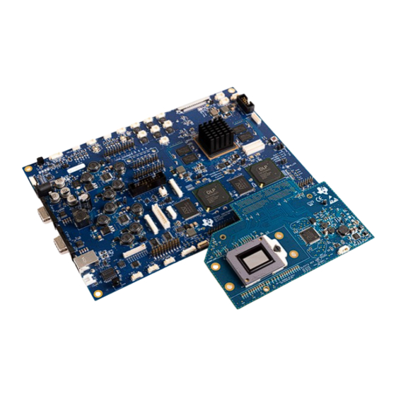
Description
The DLPC4420AEVM controller evaluation module
(EVM), when combined with the DLP660TEEVM,
DLP780TEEVM or DLP470TEEVM digital micromirror
device (DMD) EVMs, can accelerate the prototyping
time of DLP ultra high definition (UHD - 3840x2160)
system over 2000 lumens. The DLPC4420AEVM
provides a design for driving 4K UHD DMDs while
allowing for testing of custom front end systems.
The combination of the DLPC4420AEVM with any of
these 4K UHD DMD EVMs can display SPLASH, test
patterns or video from HDMI source on the DMD.
Getting Started
1. Order
DLPC4420
chipset EVMs (controller and
DMD) and an applicable power supply.
DLP DLP780TEEVM and DLPC4420AEVM Evaluation Module
DLPU126 – DECEMBER 2023
Submit Document Feedback
2. Read this User's Guide completely and the
DLPC4420 Software Programmer's Guide.
3. Download the DLPC44xx-GUI and the
DLPC4420EVM-SW.
4. Download the DMD EVM and the controller
design
Features
•
Designed to be used with a 4K UHD DMD EVM
•
Supports up to 4K UHD at 60 Hz or 1080p at 240
Hz
•
Includes two DLPC4420 controllers, two DLPA100
controller PMIC and motor drivers, and an FPGA
•
Power supply, optics, illumination source, and
extension cables are not included
•
Offers several interface options for USB, I2C and
trigger inputs and outputs
Copyright © 2023 Texas Instruments Incorporated
files.
DLP
®
Display ≥0.47-in Array 4K UHD Evaluation Module
Description
EVM
1
Table of Contents

Related Manuals for Texas Instruments DLP DLPC4420AEVM


Summary of Contents for Texas Instruments DLP DLPC4420AEVM
- Page 1 EVMs (controller and trigger inputs and outputs DMD) and an applicable power supply. DLP DLP780TEEVM and DLPC4420AEVM Evaluation Module DLPU126 – DECEMBER 2023 ® Display ≥0.47-in Array 4K UHD Evaluation Module Submit Document Feedback Copyright © 2023 Texas Instruments Incorporated...
-
Page 2: Kit Contents
DLPC4420 product page. This firmware allows the DLPC4420AEVM to drive the display chip. Figure 1-1, Figure Figure 1-3, and Figure 1-4 show the top side of each EVM. ® Display ≥0.47-in Array 4K UHD Evaluation Module DLPU126 – DECEMBER 2023 Submit Document Feedback Copyright © 2023 Texas Instruments Incorporated... - Page 3 Evaluation Module Overview Figure 1-1. DLPC4420AEVM Figure 1-2. DLP660TEEVM Figure 1-3. DLP470TEEVM DLPU126 – DECEMBER 2023 ® Display ≥0.47-in Array 4K UHD Evaluation Module Submit Document Feedback Copyright © 2023 Texas Instruments Incorporated...
-
Page 4: Specification
4k/UHD DLP080 The system block diagram Figure 1-5 details the functionality and control when using the DLP660TEEVM and DLPC4420AEVM. ® Display ≥0.47-in Array 4K UHD Evaluation Module DLPU126 – DECEMBER 2023 Submit Document Feedback Copyright © 2023 Texas Instruments Incorporated... - Page 5 • Optics • Illumination module and source • Front-End Vx1 Source capable of running at 600 MHz pixel clock DLPU126 – DECEMBER 2023 ® Display ≥0.47-in Array 4K UHD Evaluation Module Submit Document Feedback Copyright © 2023 Texas Instruments Incorporated...
- Page 6 TP31 TP25 TP37, TP38, TP40- TP45 TP35 TP39 TP46- TP36 TP28 TP55 Figure 2-1. DLPC4420AEVM Test Points and Connectors ® Display ≥0.47-in Array 4K UHD Evaluation Module DLPU126 – DECEMBER 2023 Submit Document Feedback Copyright © 2023 Texas Instruments Incorporated...
- Page 7 Mini-USB Cable SM_PIC (Actuator Test Points) Cable Cable SSI_TSP Test Points ADC Integrating Sensor Board I/F Cable D_BLK Cable DLPU126 – DECEMBER 2023 ® Display ≥0.47-in Array 4K UHD Evaluation Module Submit Document Feedback Copyright © 2023 Texas Instruments Incorporated...
- Page 8 S_P1_HSYNC TP27 S_P_CLK1 TP28 CW_PWM2 TP29 S_P_DATAEN1 TP30 M_P_CLK1 TP31 P1P1V_S TP32 M_P_DATAEN1 TP33 M_P1_HSYNC TP34 M_P1_VSYNC TP35 P1P8V_S ® Display ≥0.47-in Array 4K UHD Evaluation Module DLPU126 – DECEMBER 2023 Submit Document Feedback Copyright © 2023 Texas Instruments Incorporated...
- Page 9 TP47 LED_DIN TP48 ADC_SCLK TP49 ADC_SDO TP50 LED_DOUT TP51 LED_OE TP52 LED_DIR TP53 ADC_RST TP54 ADC_SDIN TP55 ADC_CSZ TP500 DLPU126 – DECEMBER 2023 ® Display ≥0.47-in Array 4K UHD Evaluation Module Submit Document Feedback Copyright © 2023 Texas Instruments Incorporated...
- Page 10 TP1- TP30 TP10,TP12,TP14, TP11,TP13,TP15, TP16,TP17,TP22, TP18,TP19,TP23, TP24,TP25,TP26, TP28,TP29 TP27 TP30 TP32 J500 Figure 2-2. DLP660TEEVM Test Points and Connectors ® Display ≥0.47-in Array 4K UHD Evaluation Module DLPU126 – DECEMBER 2023 Submit Document Feedback Copyright © 2023 Texas Instruments Incorporated...
- Page 11 (*) - These signals are not internally connected in the DMD 2.2.2.2 DLP660TEEVM Connectors Reference Designator Description Physical Connection Type Cable J500 FMC Connector Cable DLPU126 – DECEMBER 2023 ® Display ≥0.47-in Array 4K UHD Evaluation Module Submit Document Feedback Copyright © 2023 Texas Instruments Incorporated...
- Page 12 TP23- TP26 TP28 TP27 TP10 J500 Figure 2-3. DLP470TEEVM Test Points and Connectors ® Display ≥0.47-in Array 4K UHD Evaluation Module DLPU126 – DECEMBER 2023 Submit Document Feedback Copyright © 2023 Texas Instruments Incorporated...
- Page 13 BIST_C TP26 BIST_D TP27 TP28 2.2.3.2 DLP470TEEVM Connectors Reference Designator Description Physical Connection Type Cable J500 FMC Connector Cable DLPU126 – DECEMBER 2023 ® Display ≥0.47-in Array 4K UHD Evaluation Module Submit Document Feedback Copyright © 2023 Texas Instruments Incorporated...
- Page 14 TP27 TP25 TP28 & TP33 TP31 TP38 TP26 TP41 TP40 J500 TP29 Figure 2-4. DLP780TEEVM Test Points and Connectors ® Display ≥0.47-in Array 4K UHD Evaluation Module DLPU126 – DECEMBER 2023 Submit Document Feedback Copyright © 2023 Texas Instruments Incorporated...
- Page 15 TEMP_ALERT TP38 THERMAL_FLAG TP41 VRESET_EXT 2.2.4.2 DLP780TEEVM Connectors Reference Designator Description Physical Connection Type Cable J500 FMC Connector Cable DLPU126 – DECEMBER 2023 ® Display ≥0.47-in Array 4K UHD Evaluation Module Submit Document Feedback Copyright © 2023 Texas Instruments Incorporated...
- Page 16 DLPC4420AEVM. The process is the same for use with the DLP470TEEVM and DLP780TEEVM. Figure 2-5. EVMs Connected ® Display ≥0.47-in Array 4K UHD Evaluation Module DLPU126 – DECEMBER 2023 Submit Document Feedback Copyright © 2023 Texas Instruments Incorporated...
-
Page 17: Quick Start
Connecting the power supply when the switch is in the off position can prevent damage to the DLPC4420AEVM from poor power connections. The image below shows SW1 in the on position. DLPU126 – DECEMBER 2023 ® Display ≥0.47-in Array 4K UHD Evaluation Module Submit Document Feedback Copyright © 2023 Texas Instruments Incorporated... - Page 18 DLPC44xx GUI supports USB and I2C communication. To change these settings, please go to Edit- >Preferences->Communication. Figure 3-2. DeVaSys Communication Configuration ® Display ≥0.47-in Array 4K UHD Evaluation Module DLPU126 – DECEMBER 2023 Submit Document Feedback Copyright © 2023 Texas Instruments Incorporated...
- Page 19 3. Projector Control Configuration: a. Run the DLPC44xx GUI tool and select the Projector Control sub-tool. Figure 3-5. Projector Control Menu DLPU126 – DECEMBER 2023 ® Display ≥0.47-in Array 4K UHD Evaluation Module Submit Document Feedback Copyright © 2023 Texas Instruments Incorporated...
- Page 20 If the user wants to use one Projector Control file at a time, then deselect the files to hide before selecting OK. Figure 3-7. Projector Control File for the Chosen Chipset ® Display ≥0.47-in Array 4K UHD Evaluation Module DLPU126 – DECEMBER 2023 Submit Document Feedback Copyright © 2023 Texas Instruments Incorporated...
- Page 21 DLPC4420_Software_Files folder and select the “Flash_DLPC4420_DLP660TE_p66_TRP_4KUHD_S610_LED.img” file and click on open. Figure 3-9. Loading the Flash Image DLPU126 – DECEMBER 2023 ® Display ≥0.47-in Array 4K UHD Evaluation Module Submit Document Feedback Copyright © 2023 Texas Instruments Incorporated...
- Page 22 Red LED appears after a few seconds. The Red LED shuts off and a green LED begins blinking. After the blinking LED appears, the DLP Texas Instruments logo is visible on the DMD for a few seconds and appear as or similar to what is seen in Figure 3-12.
- Page 23 I/O POWER Power Configuration J2-6 POWER J2-7 OUTPUT J2-8 TDO1 OUTPUT J2-9 INPUT J2-10 TMS1 OUTPUT J2-11 TRSTZ OUTPUT DLPU126 – DECEMBER 2023 ® Display ≥0.47-in Array 4K UHD Evaluation Module Submit Document Feedback Copyright © 2023 Texas Instruments Incorporated...
- Page 24 USB cable between the EVM and the PC and allow the PC to detect the EVM USB connection. ® Display ≥0.47-in Array 4K UHD Evaluation Module DLPU126 – DECEMBER 2023 Submit Document Feedback Copyright © 2023 Texas Instruments Incorporated...
- Page 25 ISSI flash part. More detailed information can be found in the comments at the top of the text file. Figure 3-15. Flash Device Parameters Text File DLPU126 – DECEMBER 2023 ® Display ≥0.47-in Array 4K UHD Evaluation Module Submit Document Feedback Copyright © 2023 Texas Instruments Incorporated...
-
Page 26: Troubleshooting
Figure 3-19. Device Programming Delay Increase Tool bars or panels missing Figure 3-20. Tool Bar and Panel Display Settings ® Display ≥0.47-in Array 4K UHD Evaluation Module DLPU126 – DECEMBER 2023 Submit Document Feedback Copyright © 2023 Texas Instruments Incorporated... -
Page 27: Additional Information
Eye or skin irritation can result from exposure. Use appropriate shielding. Do not look at the operating lamp. Eye injury can result. Trademarks ® is a registered trademark of Texas Instruments. All trademarks are the property of their respective owners. 6 Related Documentation from Texas Instruments DLP660TE Data Sheet: DLP660TE Digital Micromirror Device (DMD),... - Page 28 STANDARD TERMS FOR EVALUATION MODULES Delivery: TI delivers TI evaluation boards, kits, or modules, including any accompanying demonstration software, components, and/or documentation which may be provided together or separately (collectively, an “EVM” or “EVMs”) to the User (“User”) in accordance with the terms set forth herein.
- Page 29 www.ti.com Regulatory Notices: 3.1 United States 3.1.1 Notice applicable to EVMs not FCC-Approved: FCC NOTICE: This kit is designed to allow product developers to evaluate electronic components, circuitry, or software associated with the kit to determine whether to incorporate such items in a finished product and software developers to write software applications for use with the end product.
- Page 30 www.ti.com Concernant les EVMs avec antennes détachables Conformément à la réglementation d'Industrie Canada, le présent émetteur radio peut fonctionner avec une antenne d'un type et d'un gain maximal (ou inférieur) approuvé pour l'émetteur par Industrie Canada. Dans le but de réduire les risques de brouillage radioélectrique à...
- Page 31 www.ti.com EVM Use Restrictions and Warnings: 4.1 EVMS ARE NOT FOR USE IN FUNCTIONAL SAFETY AND/OR SAFETY CRITICAL EVALUATIONS, INCLUDING BUT NOT LIMITED TO EVALUATIONS OF LIFE SUPPORT APPLICATIONS. 4.2 User must read and apply the user guide and other available documentation provided by TI regarding the EVM prior to handling or using the EVM, including without limitation any warning or restriction notices.
- Page 32 Notwithstanding the foregoing, any judgment may be enforced in any United States or foreign court, and TI may seek injunctive relief in any United States or foreign court. Mailing Address: Texas Instruments, Post Office Box 655303, Dallas, Texas 75265 Copyright © 2023, Texas Instruments Incorporated...
-
Page 33: Important Notice
TI products. TI’s provision of these resources does not expand or otherwise alter TI’s applicable warranties or warranty disclaimers for TI products. TI objects to and rejects any additional or different terms you may have proposed. IMPORTANT NOTICE Mailing Address: Texas Instruments, Post Office Box 655303, Dallas, Texas 75265 Copyright © 2023, Texas Instruments Incorporated...