
Related Manuals for Texas Instruments DS90UB949A-Q1EVM


Summary of Contents for Texas Instruments DS90UB949A-Q1EVM
- Page 1 DS90UH949A-Q1EVM or DS90UB949A-Q1EVM User's Guide Literature Number: SNLU232A August 2018 – Revised May 2019...
-
Page 2: Table Of Contents
Contents ............. DS90UH949A-Q1EVM or DS90UB949A-Q1EVM User's Guide ......................General Description ........................Features ....................... System Requirements ..................Contents of the Demo Evaluation Kit ......................Applications Diagram ......................Typical Configuration ......................Quick Start Guide ....................Default Jumper Settings ....................Default Switch Settings .................... - Page 3 B-7. Board Layer - Ground - 2 ...................... B-8. Board Layer - Bottom ..................... B-9. Board Layer - Bottom Solder SNLU232A – August 2018 – Revised May 2019 List of Figures Submit Documentation Feedback Copyright © 2018–2019, Texas Instruments Incorporated...
- Page 4 ..............1-13. Configuration Select (MODE_SEL1) - SW-DIP8 - S6 ......................1-14. IDx SW-DIP8 - S3 ......................2-1. Bill of Materials List of Tables SNLU232A – August 2018 – Revised May 2019 Submit Documentation Feedback Copyright © 2018–2019, Texas Instruments Incorporated...
-
Page 5: Ds90Uh949A-Q1Evm Or Ds90Ub949A-Q1Evm User's Guide
In this document: 1. The DS90UH949A-Q1EVM and DS90UB949A-Q1EVM devices are referred to as DS90Ux949A- Q1EVM. 2. The DS90UH949A-Q1 and DS90UB949A-Q1 devices are referred to as DS90Ux949A-Q1. -
Page 6: Features
4. 12-V power supply at approximately 1 A (required) Contents of the Demo Evaluation Kit 1. One EVM board with the DS90Ux949A-Q1 DS90UH949A-Q1EVM or DS90UB949A-Q1EVM User's Guide SNLU232A – August 2018 – Revised May 2019 Submit Documentation Feedback Copyright © 2018–2019, Texas Instruments Incorporated... -
Page 7: Applications Diagram
DS90Ux949A Video Processor Dual FPD-LINK III Cluster, Head Unit oLDI FPD-Link III Display Deserializer Figure 1-2. Typical Configuration SNLU232A – August 2018 – Revised May 2019 DS90UH949A-Q1EVM or DS90UB949A-Q1EVM User's Guide Submit Documentation Feedback Copyright © 2018–2019, Texas Instruments Incorporated... -
Page 8: Quick Start Guide
5. Connect J34 with the miniUSB cable to PC USB port (5-pin_ to USB A (4-pin)) For details of pin names and pin functions, see the DS90Ux949A-Q1 datasheet. DS90UH949A-Q1EVM or DS90UB949A-Q1EVM User's Guide SNLU232A – August 2018 – Revised May 2019 Submit Documentation Feedback Copyright ©... -
Page 9: Interfacing To The Evm
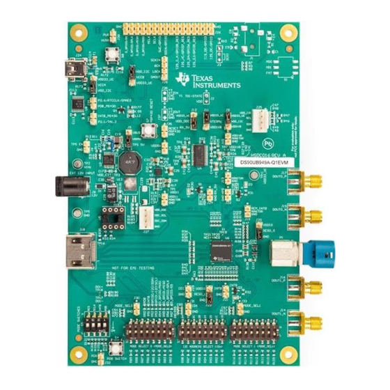
DS90Ux949A Default INPUT HERE Configuration DOUT1+ (option) DOUT1- MODE_SEL0 MODE_SEL1 (option) MOMENTARY Figure 1-3. Interfacing to the EVM SNLU232A – August 2018 – Revised May 2019 DS90UH949A-Q1EVM or DS90UB949A-Q1EVM User's Guide Submit Documentation Feedback Copyright © 2018–2019, Texas Instruments Incorporated... -
Page 10: Default Jumper Settings
1 ON (silk screen L side), 2-8 OFF (silk screen H side) 1-2 OFF (silk screen H side), 3-4 ON (silk screen L side) DS90UH949A-Q1EVM or DS90UB949A-Q1EVM User's Guide SNLU232A – August 2018 – Revised May 2019 Submit Documentation Feedback... -
Page 11: Demo Board Connections
Description mini USB 5 pin Table 1-8. I2C/CCI Interface Header J25 Designator Signal J25.1 VDDI2C J25.2 J25.3 J25.4 SNLU232A – August 2018 – Revised May 2019 DS90UH949A-Q1EVM or DS90UB949A-Q1EVM User's Guide Submit Documentation Feedback Copyright © 2018–2019, Texas Instruments Incorporated... -
Page 12: Gpio/Audio Interface
If available, remote EDID is copied into internal SRAM EDID. Table 1-12. Configuration Select (MODE_SEL0) -- SW-DIP8 - S2 MODE # EDID_SEL AUX_I2S Only set one high. DS90UH949A-Q1EVM or DS90UB949A-Q1EVM User's Guide SNLU232A – August 2018 – Revised May 2019 Submit Documentation Feedback Copyright © 2018–2019, Texas Instruments Incorporated... -
Page 13: Configuration Select (Mode_Sel1) - Sw-Dip8 - S6
0x12 0x24 S3.5 0x14 0x28 S3.6 0x16 0x2C S3.7 0x18 0x30 S3.8 0x1A 0x34 Only set one high. SNLU232A – August 2018 – Revised May 2019 DS90UH949A-Q1EVM or DS90UB949A-Q1EVM User's Guide Submit Documentation Feedback Copyright © 2018–2019, Texas Instruments Incorporated... -
Page 14: Alp Software Setup
USB cable. Power the DS90Ux949A-Q1EVM board with a 12-VDC power supply to launch the “Found New Hardware Wizard” on the PC or laptop. DS90UH949A-Q1EVM or DS90UB949A-Q1EVM User's Guide SNLU232A – August 2018 – Revised May 2019 Submit Documentation Feedback... -
Page 15: Start-Up - Software Description
Make sure all the software has been installed and the hardware is powered on and connected to the PC. Execute “Analog LaunchPAD” shortcut from the start menu. The default start menu location is under All Programs → Texas Instruments → Analog LaunchPAD vx.x.x → Analog LaunchPAD to start MainGUI.exe. -
Page 16: Initial Alp Screen
ALP Software Setup www.ti.com Under the Devices tab, select “DS90UH949” for the DS90UB949A-Q1EVM or "DS90UB949" for the DS90UB949A-Q1EVM to open up the device profile with its associated tabs. Figure 1-5. Initial ALP Screen After selecting the DS90Ux949, the screen shown in Figure 1-6 should appear. -
Page 17: Information Tab
The Information tab is shown in Figure 1-7. Note the device revision could be different. Figure 1-7. ALP Information Tab SNLU232A – August 2018 – Revised May 2019 DS90UH949A-Q1EVM or DS90UB949A-Q1EVM User's Guide Submit Documentation Feedback Copyright © 2018–2019, Texas Instruments Incorporated... -
Page 18: Hdmi Tab
ALP Software Setup www.ti.com 1.11.6 HDMI Tab The HDMI tab is shown in Figure 1-8. Figure 1-8. ALP HDMI Tab DS90UH949A-Q1EVM or DS90UB949A-Q1EVM User's Guide SNLU232A – August 2018 – Revised May 2019 Submit Documentation Feedback Copyright © 2018–2019, Texas Instruments Incorporated... -
Page 19: Pattern Generator Tab
1.11.7 Pattern Generator Tab The SER Pattern Generator tab is shown in Figure 1-9. Figure 1-9. ALP Pattern Generator Tab SNLU232A – August 2018 – Revised May 2019 DS90UH949A-Q1EVM or DS90UB949A-Q1EVM User's Guide Submit Documentation Feedback Copyright © 2018–2019, Texas Instruments Incorporated... -
Page 20: Registers Tab
ALP Software Setup www.ti.com 1.11.8 Registers Tab The Registers tab is shown in Figure 1-10. Figure 1-10. ALP Registers Tab DS90UH949A-Q1EVM or DS90UB949A-Q1EVM User's Guide SNLU232A – August 2018 – Revised May 2019 Submit Documentation Feedback Copyright © 2018–2019, Texas Instruments Incorporated... -
Page 21: Registers Tab - Address 0X00 Selected
1-11. Note that the “Value:” box, , will now show the hex value of that register. Figure 1-11. ALP Device ID Selected SNLU232A – August 2018 – Revised May 2019 DS90UH949A-Q1EVM or DS90UB949A-Q1EVM User's Guide Submit Documentation Feedback Copyright © 2018–2019, Texas Instruments Incorporated... -
Page 22: Registers Tab - Address 0X00 Expanded
Click “Apply” to write to the register and “Refresh” to see the new value of the selected (highlighted) register. The box toggles on every mouse click. DS90UH949A-Q1EVM or DS90UB949A-Q1EVM User's Guide SNLU232A – August 2018 – Revised May 2019 Submit Documentation Feedback... -
Page 23: Scripting Tab
ALP Framework application. SNLU232A – August 2018 – Revised May 2019 DS90UH949A-Q1EVM or DS90UB949A-Q1EVM User's Guide Submit Documentation Feedback Copyright © 2018–2019, Texas Instruments Incorporated... -
Page 24: Troubleshooting Alp Software
Figure 1-14. USB2ANY Setup 1. Highlight the incorrect profile in the Defined ALP Devices list and click the remove button. Figure 1-15. Remove Incorrect Profile DS90UH949A-Q1EVM or DS90UB949A-Q1EVM User's Guide SNLU232A – August 2018 – Revised May 2019 Submit Documentation Feedback... -
Page 25: Add Correct Profile
Figure 1-16. Add Correct Profile 3. Click Ok and the correct profile should load. Figure 1-17. Finish Setup SNLU232A – August 2018 – Revised May 2019 DS90UH949A-Q1EVM or DS90UB949A-Q1EVM User's Guide Submit Documentation Feedback Copyright © 2018–2019, Texas Instruments Incorporated... -
Page 26: Alp Does Not Detect The Evm
“Human Interface Devices” as shown in Figure 1-19. Figure 1-19. Windows 7, ALP USB Driver DS90UH949A-Q1EVM or DS90UB949A-Q1EVM User's Guide SNLU232A – August 2018 – Revised May 2019 Submit Documentation Feedback Copyright © 2018–2019, Texas Instruments Incorporated... -
Page 27: Alp In Demo Mode
After demo mode is disabled, the ALP software will poll the ALP hardware. The ALP software will update and only have “DS90UH949” or "DS90UB949" under the “Devices” drop-down menu. SNLU232A – August 2018 – Revised May 2019 DS90UH949A-Q1EVM or DS90UB949A-Q1EVM User's Guide Submit Documentation Feedback Copyright © 2018–2019, Texas Instruments Incorporated... -
Page 28: Typical Connection And Test Equipment
FPD-Link III HDMI Contents of EVM Graphics Controller / Video Processor Board Figure 1-23. Typical Test Setup for Evaluation DS90UH949A-Q1EVM or DS90UB949A-Q1EVM User's Guide SNLU232A – August 2018 – Revised May 2019 Submit Documentation Feedback Copyright © 2018–2019, Texas Instruments Incorporated... -
Page 29: Equipment References
100-Ω differential impedance for high-speed data applications. Leoni Dacar 538 series cable: www.leoni-automotive-cables.com Rosenberger HSD connector: www.rosenberger.de/en/Products/35_Automotive_HSD.php SNLU232A – August 2018 – Revised May 2019 DS90UH949A-Q1EVM or DS90UB949A-Q1EVM User's Guide Submit Documentation Feedback Copyright © 2018–2019, Texas Instruments Incorporated... -
Page 30: Bill Of Materials
25 V, +/- 10%, 2TE3 6.3 ohm, SMD 0.01uF CAP, CERM, 0603 06031C103JAT2 0.01 µF, 100 V,+/- 5%, X7R, 0603 Bill of Materials SNLU232A – August 2018 – Revised May 2019 Submit Documentation Feedback Copyright © 2018–2019, Texas Instruments Incorporated... - Page 31 Machine Screw, Screw NY PMS 440 B and F Round, #4-40 x 0025 PH Fastener Supply 1/4, Nylon, Philips panhead SNLU232A – August 2018 – Revised May 2019 Bill of Materials Submit Documentation Feedback Copyright © 2018–2019, Texas Instruments Incorporated...
- Page 32 0402 CRCW040222K1 Vishay-Dale 0.063 W, 0402 FKED R13, R17, R26, RES, 0, 5%, 0.1 0603 CRCW06030000 Vishay-Dale W, 0603 Z0EA Bill of Materials SNLU232A – August 2018 – Revised May 2019 Submit Documentation Feedback Copyright © 2018–2019, Texas Instruments Incorporated...
- Page 33 FKED R68, R77, R104 82.5k RES, 82.5 k, 1%, 0402 CRCW040282K5 Vishay-Dale 0.063 W, AEC- FKED Q200 Grade 0, 0402 SNLU232A – August 2018 – Revised May 2019 Bill of Materials Submit Documentation Feedback Copyright © 2018–2019, Texas Instruments Incorporated...
- Page 34 SH-J4, SH-J5, Gold plated, Closed Top SH-J6, SH-J7, Black SH-J8 TP2, TP5, TP11 Terminal, Turret, Keystone1502-2 1502-2 Keystone TH, Double Bill of Materials SNLU232A – August 2018 – Revised May 2019 Submit Documentation Feedback Copyright © 2018–2019, Texas Instruments Incorporated...
- Page 35 Array for High- Instruments Speed Data Interfaces, 4 Channels, -40 to +85 degC, 6-pin SON (DRY), Green (RoHS and no Sb/Br) SNLU232A – August 2018 – Revised May 2019 Bill of Materials Submit Documentation Feedback Copyright © 2018–2019, Texas Instruments Incorporated...
- Page 36 Header, 100mil, Header, 2x1, 5-146261-1 TE Connectivity 2x1, Gold, TH 100mil Header, 100mil, 3x1 Header TSW-103-07-G- Samtec 3x1, Gold, TH Bill of Materials SNLU232A – August 2018 – Revised May 2019 Submit Documentation Feedback Copyright © 2018–2019, Texas Instruments Incorporated...
- Page 37 Stereo ADC with Instruments Single-Ended Inputs, PW0014A (TSSOP-14) Single High D0008A Texas Speed Instruments Differential Driver, 8-pin Narrow SOIC, Pb-Free SNLU232A – August 2018 – Revised May 2019 Bill of Materials Submit Documentation Feedback Copyright © 2018–2019, Texas Instruments Incorporated...
- Page 38 SMD, 4-Leads, FXO-HC736R-96 Fox Electronics 3.3 Vdc, SMD Body 7x5mm OSC, 148.5 7x5mm FVXO-LC73BR- MHz, LVDS, 3.3 148.5 V, SMD Bill of Materials SNLU232A – August 2018 – Revised May 2019 Submit Documentation Feedback Copyright © 2018–2019, Texas Instruments Incorporated...
-
Page 39: Evm Pcb Schematics
Appendix A SNLU232A – August 2018 – Revised May 2019 EVM PCB Schematics Figure A-1. Schematic - Block Diagram SNLU232A – August 2018 – Revised May 2019 EVM PCB Schematics Submit Documentation Feedback Copyright © 2018–2019, Texas Instruments Incorporated... -
Page 40: Schematic - Ds90Uh949A-Q1 And Power Decoupling
Appendix A www.ti.com DS90UB949ATRGCRQ1 t variant -002 DS90UH949ATRGCRQ1 t variant -001 Figure A-2. Schematic - DS90UH949A-Q1 and Power Decoupling EVM PCB Schematics SNLU232A – August 2018 – Revised May 2019 Submit Documentation Feedback Copyright © 2018–2019, Texas Instruments Incorporated... -
Page 41: Schematic - Msp430
Appendix A www.ti.com Figure A-3. Schematic - MSP430 SNLU232A – August 2018 – Revised May 2019 EVM PCB Schematics Submit Documentation Feedback Copyright © 2018–2019, Texas Instruments Incorporated... - Page 42 Appendix A www.ti.com Figure A-4. Schematic - PDB, IDx and MODE_SEL Switches EVM PCB Schematics SNLU232A – August 2018 – Revised May 2019 Submit Documentation Feedback Copyright © 2018–2019, Texas Instruments Incorporated...
-
Page 43: Schematic - Hdmi, Hsd, Sma, I2C, Ddc, Cec And Gpio/I2S/Spi Connectors
Appendix A www.ti.com Figure A-5. Schematic - HDMI, HSD, SMA, I2C, DDC, CEC and GPIO/I2S/SPI Connectors SNLU232A – August 2018 – Revised May 2019 EVM PCB Schematics Submit Documentation Feedback Copyright © 2018–2019, Texas Instruments Incorporated... -
Page 44: Schematic - Leds
Appendix A www.ti.com Figure A-6. Schematic - LEDs EVM PCB Schematics SNLU232A – August 2018 – Revised May 2019 Submit Documentation Feedback Copyright © 2018–2019, Texas Instruments Incorporated... -
Page 45: Schematic - Audio (Not Populated)
Appendix A www.ti.com Figure A-7. Schematic - Audio (Not Populated) SNLU232A – August 2018 – Revised May 2019 EVM PCB Schematics Submit Documentation Feedback Copyright © 2018–2019, Texas Instruments Incorporated... -
Page 46: Schematic - Power Regulators
Appendix A www.ti.com Figure A-8. Schematic - Power Regulators EVM PCB Schematics SNLU232A – August 2018 – Revised May 2019 Submit Documentation Feedback Copyright © 2018–2019, Texas Instruments Incorporated... -
Page 47: Schematic - Hardware
Appendix A www.ti.com Figure A-9. Schematic - Hardware SNLU232A – August 2018 – Revised May 2019 EVM PCB Schematics Submit Documentation Feedback Copyright © 2018–2019, Texas Instruments Incorporated... -
Page 48: Board Layout
Appendix B SNLU232A – August 2018 – Revised May 2019 Board Layout Board Layers Figure B-1. Board Layer - Top Overlay Board Layout SNLU232A – August 2018 – Revised May 2019 Submit Documentation Feedback Copyright © 2018–2019, Texas Instruments Incorporated... -
Page 49: Board Layer - Top Solder
Appendix B www.ti.com Figure B-2. Board Layer - Top Solder SNLU232A – August 2018 – Revised May 2019 Board Layout Submit Documentation Feedback Copyright © 2018–2019, Texas Instruments Incorporated... -
Page 50: Board Layer - Top
Appendix B www.ti.com Figure B-3. Board Layer - Top Board Layout SNLU232A – August 2018 – Revised May 2019 Submit Documentation Feedback Copyright © 2018–2019, Texas Instruments Incorporated... -
Page 51: Board Layer - Ground-1
Appendix B www.ti.com Figure B-4. Board Layer - Ground-1 SNLU232A – August 2018 – Revised May 2019 Board Layout Submit Documentation Feedback Copyright © 2018–2019, Texas Instruments Incorporated... -
Page 52: Board Layer - Signal Layer
Appendix B www.ti.com Figure B-5. Board Layer - Signal Layer Board Layout SNLU232A – August 2018 – Revised May 2019 Submit Documentation Feedback Copyright © 2018–2019, Texas Instruments Incorporated... -
Page 53: Board Layer - Power Split/Gnd
Appendix B www.ti.com Figure B-6. Board Layer - Power Split/GND SNLU232A – August 2018 – Revised May 2019 Board Layout Submit Documentation Feedback Copyright © 2018–2019, Texas Instruments Incorporated... -
Page 54: Board Layer - Ground
Appendix B www.ti.com Figure B-7. Board Layer - Ground - 2 Board Layout SNLU232A – August 2018 – Revised May 2019 Submit Documentation Feedback Copyright © 2018–2019, Texas Instruments Incorporated... -
Page 55: Board Layer - Bottom
Appendix B www.ti.com Figure B-8. Board Layer - Bottom SNLU232A – August 2018 – Revised May 2019 Board Layout Submit Documentation Feedback Copyright © 2018–2019, Texas Instruments Incorporated... -
Page 56: Board Layer - Bottom Solder
Appendix B www.ti.com Figure B-9. Board Layer - Bottom Solder Board Layout SNLU232A – August 2018 – Revised May 2019 Submit Documentation Feedback Copyright © 2018–2019, Texas Instruments Incorporated... -
Page 57: Revision History
Added content to the General Description section ....................• Changed S4, S7, S8 BOM information ......................• Changed U6 BOM information SNLU232A – August 2018 – Revised May 2019 Revision History Submit Documentation Feedback Copyright © 2018–2019, Texas Instruments Incorporated... - Page 58 STANDARD TERMS FOR EVALUATION MODULES Delivery: TI delivers TI evaluation boards, kits, or modules, including any accompanying demonstration software, components, and/or documentation which may be provided together or separately (collectively, an “EVM” or “EVMs”) to the User (“User”) in accordance with the terms set forth herein.
- Page 59 www.ti.com Regulatory Notices: 3.1 United States 3.1.1 Notice applicable to EVMs not FCC-Approved: FCC NOTICE: This kit is designed to allow product developers to evaluate electronic components, circuitry, or software associated with the kit to determine whether to incorporate such items in a finished product and software developers to write software applications for use with the end product.
- Page 60 www.ti.com Concernant les EVMs avec antennes détachables Conformément à la réglementation d'Industrie Canada, le présent émetteur radio peut fonctionner avec une antenne d'un type et d'un gain maximal (ou inférieur) approuvé pour l'émetteur par Industrie Canada. Dans le but de réduire les risques de brouillage radioélectrique à...
- Page 61 www.ti.com EVM Use Restrictions and Warnings: 4.1 EVMS ARE NOT FOR USE IN FUNCTIONAL SAFETY AND/OR SAFETY CRITICAL EVALUATIONS, INCLUDING BUT NOT LIMITED TO EVALUATIONS OF LIFE SUPPORT APPLICATIONS. 4.2 User must read and apply the user guide and other available documentation provided by TI regarding the EVM prior to handling or using the EVM, including without limitation any warning or restriction notices.
- Page 62 Notwithstanding the foregoing, any judgment may be enforced in any United States or foreign court, and TI may seek injunctive relief in any United States or foreign court. Mailing Address: Texas Instruments, Post Office Box 655303, Dallas, Texas 75265 Copyright © 2019, Texas Instruments Incorporated...
- Page 63 TI products. TI’s provision of these resources does not expand or otherwise alter TI’s applicable warranties or warranty disclaimers for TI products. Mailing Address: Texas Instruments, Post Office Box 655303, Dallas, Texas 75265 Copyright © 2019, Texas Instruments Incorporated...