
Related Manuals for Texas Instruments DRV8803


Summary of Contents for Texas Instruments DRV8803
- Page 1 DRV8803/04/05/06 Evaluation Module User's Guide Literature Number: SLVU574B September 2011 – Revised July 2019...
-
Page 2: Table Of Contents
Speed Control ....................4.10 Acceleration Control ....................... 4.11 Diagnostic Output ................ 4.12 Controlling the EVM Using External Signals ........................Schematics Table of Contents SLVU574B – September 2011 – Revised July 2019 Submit Documentation Feedback Copyright © 2011–2019, Texas Instruments Incorporated... - Page 3 Motor Control ................DRV88003/04/05 Motor Control Windows ................DRV88003/04/05 Speed Control Windows ..............DRV88003/04/05 Acceleration Control Windows ....................... Acceleration Control SLVU574B – September 2011 – Revised July 2019 List of Figures Submit Documentation Feedback Copyright © 2011–2019, Texas Instruments Incorporated...
-
Page 4: Trademarks
Trademarks All trademarks are the property of their respective owners. List of Figures SLVU574B – September 2011 – Revised July 2019 Submit Documentation Feedback Copyright © 2011–2019, Texas Instruments Incorporated... -
Page 5: Pcb
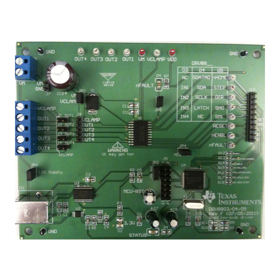
DRV8803/04/05/06 Evaluation Module This document is provided as a supplement to the DRV8803/DRV8804/DRV8805/DRV8806 datasheets. It details the hardware implementation of the DRV8803/04/05/06 EVM Customer Evaluation Module (EVM). Figure 1. DRV8803/04/05/06 PCB SLVU574B – September 2011 – Revised July 2019 DRV8803/04/05/06 Evaluation Module Submit Documentation Feedback Copyright ©... -
Page 6: Test Points
For those pins that change functionality depending on the respective device being used, a table is provided with corresponding function name on its particular column. Test Points Figure 2. Test Points DRV8803/04/05/06 Evaluation Module SLVU574B – September 2011 – Revised July 2019 Submit Documentation Feedback Copyright © 2011–2019, Texas Instruments Incorporated... -
Page 7: Connectors
User must power the EVM using the correct polarity. User must apply VM according to datasheet recommended parameters. Figure 3. Power Connectors SLVU574B – September 2011 – Revised July 2019 DRV8803/04/05/06 Evaluation Module Submit Documentation Feedback Copyright © 2011–2019, Texas Instruments Incorporated... -
Page 8: Jumpers/Resistors
EVM (DRV8803, 04, 05 or 06). The MCU powers up based on these resistors. However, the GUI can be used to select the device on the EVM too. If the user changes the DRV8803 to another flavor of the IC (namely DRV8804/05/06) the appropriate tab in the GUI should be selected and ‘CONFIGURE DEVICE’... -
Page 9: Motor Outputs
Although feasible, we do not recommend the connection of any motor into the test clips as these are Kelvin connections and are not rated for high current output. All pins are labeled on the silk-screen for clarity. SLVU574B – September 2011 – Revised July 2019 DRV8803/04/05/06 Evaluation Module Submit Documentation Feedback Copyright © 2011–2019, Texas Instruments Incorporated... -
Page 10: Gui Software Installation
Recommended RAM - 4 GB or higher • Recommended CPU Operating Speed – 3.3 GHz or higher Installation Procedure The following procedure helps you install the DRV8803/04/05/06 EVM GUI 1. Double click on the Setup_DRV8803/04/05/06_EVM.exe as in Figure DRV8803/04/05/06 Evaluation Module SLVU574B –... -
Page 11: Setup_Drv8803/04/05/06_Evm.exe
3. In the newly open installation pop-up window, click Next. The license agreement will be displayed. Please, read through it carefully and enable the "I Accept the Agreement" radio button and press Next. SLVU574B – September 2011 – Revised July 2019 DRV8803/04/05/06 Evaluation Module Submit Documentation Feedback Copyright © 2011–2019, Texas Instruments Incorporated... -
Page 12: License Agreement
Next button. Figure 9. NI License Agreement 5. Set the default directory for the GUI Installation and click Next. DRV8803/04/05/06 Evaluation Module SLVU574B – September 2011 – Revised July 2019 Submit Documentation Feedback Copyright © 2011–2019, Texas Instruments Incorporated... -
Page 13: Installation Directory Screen
Configure the proxy settings as required. This screen is to download the LabVIEW RTE 2014 from ni.com, Click Next to continue the installation. SLVU574B – September 2011 – Revised July 2019 DRV8803/04/05/06 Evaluation Module Submit Documentation Feedback Copyright © 2011–2019, Texas Instruments Incorporated... -
Page 14: Configure Proxy
9. If the LabVIEW RTE 2014 is selected as a component to install, LabVIEW RTE downloads and performs a silent mode installation. DRV8803/04/05/06 Evaluation Module SLVU574B – September 2011 – Revised July 2019 Submit Documentation Feedback Copyright © 2011–2019, Texas Instruments Incorporated... -
Page 15: Downloading Rte
Figure 15. LabVIEW RTE Self Extraction 11. A screen appears as shown in Figure 16. It initializes the LabVIEW RTE Installation. SLVU574B – September 2011 – Revised July 2019 DRV8803/04/05/06 Evaluation Module Submit Documentation Feedback Copyright © 2011–2019, Texas Instruments Incorporated... -
Page 16: Labview Rte Installation Initialization
12. A display as shown in Figure 17 appears which indicates the progress of LabVIEW RTE installation. Figure 17. Installation of LabVIEW RTE in Progress DRV8803/04/05/06 Evaluation Module SLVU574B – September 2011 – Revised July 2019 Submit Documentation Feedback Copyright © 2011–2019, Texas Instruments Incorporated... -
Page 17: Ftdi Installation Initialization
Extract to proceed. Figure 18. FTDI Installation Initialization 15. A screen as shown in Figure 19 appears, click Next to proceed. SLVU574B – September 2011 – Revised July 2019 DRV8803/04/05/06 Evaluation Module Submit Documentation Feedback Copyright © 2011–2019, Texas Instruments Incorporated... -
Page 18: Driver Installation Wizard
17. Read through the License Agreement carefully and enable the “I Accept this Agreement” radio button and Click on Next. DRV8803/04/05/06 Evaluation Module SLVU574B – September 2011 – Revised July 2019 Submit Documentation Feedback Copyright © 2011–2019, Texas Instruments Incorporated... -
Page 19: License Agreement For Ftdi Driver
Figure 20. License Agreement for FTDI Driver 18. Click Finish to complete the Driver Installation. Figure 21. Driver Installation Completion SLVU574B – September 2011 – Revised July 2019 DRV8803/04/05/06 Evaluation Module Submit Documentation Feedback Copyright © 2011–2019, Texas Instruments Incorporated... -
Page 20: Installation Complete
GUI Software Installation www.ti.com Figure 22 appears denoting the completion of DRV8803/04/05/06 EVM GUI Installation. Click Finish. Figure 22. Installation Complete 20. A Readme window as shown in Figure 23 appears displaying the link for LV 2014 RTE. Figure 23. Readme Window DRV8803/04/05/06 Evaluation Module SLVU574B –... - Page 21 You can download National Instruments LabVIEW Run-Time Engine 2014 from the below link: LabVIEW Run-Time Engine 2014 NOTE: DRV8803/04/05/06_EVM GUI executable has been built in LabVIEW 2014 (32-bit) version, and it expects the LabVIEW Run-Time Engine version to be LabVIEW Run-Time Engine (32- bit version).
-
Page 22: The Windows Application
DRV8803 Figure 24. DRV8803 Tab The DRV8803 tab contains a diagram of the device which includes pin control and information about control signals including: nENBL, RESET, IN1, IN2, IN3, and IN4. It also includes corresponding controls to these pins (Enable Motor button, Reset button, and INx PWM and Duty Cycle number boxes). -
Page 23: Drv8804 Tab
Stepper control is implemented by controls in group boxes including: Motor Control, Speed Control, and Acceleration control. The DRV8804 tab also contains SPI package control in group box SPI Control. SLVU574B – September 2011 – Revised July 2019 DRV8803/04/05/06 Evaluation Module Submit Documentation Feedback Copyright © 2011–2019, Texas Instruments Incorporated... -
Page 24: Drv8805 Tab
Stepper control is implemented by controls in group boxes including: Motor Control, Speed Control, and Acceleration control. The DRV8805 tab also contains a look up table detailing the functionality of pins SM1 and SM0. DRV8803/04/05/06 Evaluation Module SLVU574B – September 2011 – Revised July 2019 Submit Documentation Feedback Copyright © 2011–2019, Texas Instruments Incorporated... -
Page 25: Drv8806 Tab
SPI which offers diagnostics information, said output is made available at the Fault Diagnostics group box. SLVU574B – September 2011 – Revised July 2019 DRV8803/04/05/06 Evaluation Module Submit Documentation Feedback Copyright © 2011–2019, Texas Instruments Incorporated... -
Page 26: Gui Description/Functionality
Schematic - which takes the user to a menu of different device schematics that are available for viewing. Figure 29. View This will take you to a window resembling the following: DRV8803/04/05/06 Evaluation Module SLVU574B – September 2011 – Revised July 2019 Submit Documentation Feedback Copyright © 2011–2019, Texas Instruments Incorporated... -
Page 27: Schematic Window
About - The About Page provides the details like the Name of the GUI, GUI version, Supported OS and Copyright Information. SLVU574B – September 2011 – Revised July 2019 DRV8803/04/05/06 Evaluation Module Submit Documentation Feedback Copyright © 2011–2019, Texas Instruments Incorporated... -
Page 28: Drv880X Gpio Control Signals
LO level on the respective control signals, and in special cases, an orange pin translates to an open signal, and a gray pin translates to a non-control pin. DRV8803/04/05/06 Evaluation Module SLVU574B – September 2011 – Revised July 2019 Submit Documentation Feedback Copyright © 2011–2019, Texas Instruments Incorporated... -
Page 29: Gpio Control Signals
OUT1 STEP OUT2 OUT3 OUT4 RESET nENBL Control Pin (Hi) Control Pin (LO) Non-control Pin Figure 34. GPIO Control Signals SLVU574B – September 2011 – Revised July 2019 DRV8803/04/05/06 Evaluation Module Submit Documentation Feedback Copyright © 2011–2019, Texas Instruments Incorporated... - Page 30 Reset Button (See motor control). INx – Control appears on the DRV8803 device. Toggling HI (green) sets PWM of input X to a duty cycle of 100%. Toggling LO (red) sets PWM of input X to a duty cycle of 0%. Automatically toggles in correspondence to INx sliders and % duty cycle combo boxes (See PWM control).
-
Page 31: Pwm Control
Figure 36. DRV8803 PWM Control The DRV8803 can be utilized to control DC motors. For the purpose to control DC motor speed, a slider is provided which applies a PWM to each respective input. The PWM slider consists of an 8 bit number so positions from 0 to 255 are obtained. -
Page 32: Motor Control
Once all the control signals are configured accordingly, the motor is ready to be turned. The DRV8803/04/05 Customer EVM allows for the possibility of coordinating step rates such that accelerating and decelerating profiles are achieved. Both acceleration and deceleration are controlled by the same parameters Acceleration Rate and Time Base. -
Page 33: Drv88003/04/05 Motor Control Windows
Figure 38. DRV88003/04/05 Motor Control Windows Stepper PWM Slide Bar – Appears on the DRV8803 and DRV8804. On the DRV8803 this sets all of the INx PWM slide bars to whatever the Stepper PWM slide bar is set to. This controls the PWM rate of the stepper. -
Page 34: Speed Control
Figure 40. DRV88003/04/05 Acceleration Control Windows Each respective control (slide bar or number box) automatically updates the other when it is being used. DRV8803/04/05/06 Evaluation Module SLVU574B – September 2011 – Revised July 2019 Submit Documentation Feedback Copyright © 2011–2019, Texas Instruments Incorporated... -
Page 35: 4.11 Diagnostic Output
Please note that once these resistors are de-soldered, the user cannot use the on-board MCU. Schematics Schematics for the DRV8803/04/05/06 can be found on the following pages. SLVU574B – September 2011 – Revised July 2019 DRV8803/04/05/06 Evaluation Module Submit Documentation Feedback... - Page 36 DRV8805Quad Low SideDriver - Microstepping Indexer DRV8806Quad Low SideDriver - Serial (SPI) Interface / diagnostics Size FCSM No. DWGNo. DRV8803/04/05/06EVM Scale Sheet 1 of 2 DRV8803/04/05/06 Evaluation Module SLVU574B – September 2011 – Revised July 2019 Submit Documentation Feedback Copyright © 2011–2019, Texas Instruments Incorporated...
- Page 37 Schematics www.ti.com SLVU574B – September 2011 – Revised July 2019 DRV8803/04/05/06 Evaluation Module Submit Documentation Feedback Copyright © 2011–2019, Texas Instruments Incorporated...
- Page 38 DRV8806Quad Low SideDriver - Serial (SPI) Interface / diagnostics DRV8806 Size FCSM No. DWGNo. DRV8803/04/05/06EVM Scale Sheet 2 of 2 DRV8803/04/05/06 Evaluation Module SLVU574B – September 2011 – Revised July 2019 Submit Documentation Feedback Copyright © 2011–2019, Texas Instruments Incorporated...
- Page 39 STANDARD TERMS FOR EVALUATION MODULES Delivery: TI delivers TI evaluation boards, kits, or modules, including any accompanying demonstration software, components, and/or documentation which may be provided together or separately (collectively, an “EVM” or “EVMs”) to the User (“User”) in accordance with the terms set forth herein.
- Page 40 www.ti.com Regulatory Notices: 3.1 United States 3.1.1 Notice applicable to EVMs not FCC-Approved: FCC NOTICE: This kit is designed to allow product developers to evaluate electronic components, circuitry, or software associated with the kit to determine whether to incorporate such items in a finished product and software developers to write software applications for use with the end product.
- Page 41 www.ti.com Concernant les EVMs avec antennes détachables Conformément à la réglementation d'Industrie Canada, le présent émetteur radio peut fonctionner avec une antenne d'un type et d'un gain maximal (ou inférieur) approuvé pour l'émetteur par Industrie Canada. Dans le but de réduire les risques de brouillage radioélectrique à...
- Page 42 www.ti.com EVM Use Restrictions and Warnings: 4.1 EVMS ARE NOT FOR USE IN FUNCTIONAL SAFETY AND/OR SAFETY CRITICAL EVALUATIONS, INCLUDING BUT NOT LIMITED TO EVALUATIONS OF LIFE SUPPORT APPLICATIONS. 4.2 User must read and apply the user guide and other available documentation provided by TI regarding the EVM prior to handling or using the EVM, including without limitation any warning or restriction notices.
- Page 43 Notwithstanding the foregoing, any judgment may be enforced in any United States or foreign court, and TI may seek injunctive relief in any United States or foreign court. Mailing Address: Texas Instruments, Post Office Box 655303, Dallas, Texas 75265 Copyright © 2019, Texas Instruments Incorporated...
- Page 44 TI products. TI’s provision of these resources does not expand or otherwise alter TI’s applicable warranties or warranty disclaimers for TI products. Mailing Address: Texas Instruments, Post Office Box 655303, Dallas, Texas 75265 Copyright © 2019, Texas Instruments Incorporated...