Table of Contents
Quick Links
Table of Contents

Related Manuals for Texas Instruments DLPDLCR660TEVM


Summary of Contents for Texas Instruments DLPDLCR660TEVM
- Page 1 Products ECD 4K UHD EVM ® User's Guide Literature Number: DLPU077 March 2019...
-
Page 2: Table Of Contents
Contents ............................Preface ............DLPDLCR660TEVM and DLPLCRDC4422EVM Overview ........................Welcome ....What is in the DLPDLCR660TEVM and DLPLCRDC4422EVM Evaluation Modules (EVMs)? ......................... EVM Boards ..................Other Items Needed for Operation ............ DLPLCRDC4422EVM and DLPDLCR660TEVM EVM Flex Cable ........................Quick Start .................... - Page 3 List of Figures .......... DLP DLPDLCR660TEVM and DLPLCRDC4422EVM Evaluation Module ....................... 1-1. DLPLCRDC4422EVM ......................1-2. DLPDLCR660TEVM ....................1-3. EVM System Block Diagram ......................1-4. Flex Cable Diagram ......................... 2-1. Flex Cables ......................2-2. EVMs Connected ......................2-3. ON/OFF Switch ................
- Page 4 List of Figures DLPU077 – March 2019 Submit Documentation Feedback Copyright © 2019, Texas Instruments Incorporated...
-
Page 5: Preface
DLP is a registered trademark of Texas Instruments. About This Guide This guide explains the hardware and software features of the DLP Products DLPDLCR660TEVM and DLPLCRDC4422EVM systems. The EVM architecture and connectors will be described along with a quick start guide on how to operate the DLPDLCR660TEVM and DLPLCRDC4422EVM EVMs using the DLPC4422 GUI. -
Page 6: Dlpdlcr660Tevm And Dlplcrdc4422Evm Overview
State Lighting Systems What is in the DLPDLCR660TEVM and DLPLCRDC4422EVM Evaluation Modules (EVMs)? The DLPDLCR660TEVM and DLPLCRDC4422EVM are designed to be used together. In fact, one cannot be operated without the other. The DLPDLCR660TEVM, which includes the DLP660TE display chip, includes the two flex cables required to connect the DLPDLCR660TEVM to the DLPLCRDC4422EVM. - Page 7 What is in the DLPDLCR660TEVM and DLPLCRDC4422EVM Evaluation Modules (EVMs)? www.ti.com Figure 1-1. DLPLCRDC4422EVM Figure 1-2. DLPDLCR660TEVM DLPU077 – March 2019 DLPDLCR660TEVM and DLPLCRDC4422EVM Overview Submit Documentation Feedback Copyright © 2019, Texas Instruments Incorporated...
-
Page 8: Evm Boards
TPS65145 used to generate the DMD's reset voltages Other Items Needed for Operation The DLPDLCR660TEVM and the DLPLCRDC4422EVM are evaluation modules (EVM) that are capable of displaying images on to the DMD. However, these EVMs do not ship with optics, illumination source, cables, power supplies, or additional hardware components. -
Page 9: Dlplcrdc4422Evm And Dlpdlcr660Tevm Evm Flex Cable
DLPLCRDC4422EVM and DLPDLCR660TEVM EVM Flex Cable www.ti.com DLPLCRDC4422EVM and DLPDLCR660TEVM EVM Flex Cable Electrical malfunctions can occur by stressing the flex cable(s) connecting the DMD circuit board to the DLPLCRDC4422EVM controller circuit board. Stressing the flex cable can be caused by: •... -
Page 10: Quick Start
DLPU077 – March 2019 Quick Start This chapter offers a quick start guide on how to connect the DLPDLCR660TEVM to the DLPLCRDC4422EVM, how to power up the DLPLCRDC4422EVM, and how to program the DLPLCRDC4422EVM to display a SPLASH image on the DMD. -
Page 11: Flex Cables
Figure 2-1. Flex Cables Repeat the above steps to connect the other end of each flex cable to the DLPLCRDC4422EVM. The EVM should look like after the flex cables have been connected to both the DLPDLCR660TEVM and the DLPLCRDC4422EVM. DLPU077 – March 2019... -
Page 12: Powering-Up The Dlplcrdc4422Evm And Preparing For The Dlplcrdc4422Evm To Be Programmed
J32 - Vx1 Swap P/N Installed - Not Swapping P and N Uninstalled - Swapping Bit Order J33 - Vx1 Swap Bit Order Installed - Not Swapping Bit Order Quick Start DLPU077 – March 2019 Submit Documentation Feedback Copyright © 2019, Texas Instruments Incorporated... -
Page 13: Programming The Dlplcrdc4422Evm And Displaying A Splash Image
Programming the DLPLCRDC4422EVM and Displaying a SPLASH image Follow these steps in order to download and configure the DLPC4422 GUI: 1. Download and install the DLPDLCR660TEVM Firmware SW package. The Projector Control (.projector) and Firmware binary(.img) files will be located in the install directory. -
Page 14: Devasys Communication Configuration
An error message may appear saying the USB driver cannot be opened. This is expected, as we have not yet enabled communication on the board. Click “OK” on this error. Quick Start DLPU077 – March 2019 Submit Documentation Feedback Copyright © 2019, Texas Instruments Incorporated... -
Page 15: Error Message
Ensure the desired Projector Control file is checked, then select OK. Note: If you want to use one Projector Control file at a time, please deselect the files you do not want to see before selecting DLPU077 – March 2019 Quick Start Submit Documentation Feedback Copyright © 2019, Texas Instruments Incorporated... -
Page 16: Projector Control File For The Chosen Chipset
Figure 2-9. Projector Control File for the Chosen Chipset d. Once this file is loaded, you can navigate through its pages to control a DLPC4422 controller. Figure 2-10. DLPC4422 Projector Control Menu Quick Start DLPU077 – March 2019 Submit Documentation Feedback Copyright © 2019, Texas Instruments Incorporated... -
Page 17: Loading The Flash Image
4. Flash Loader Configuration: a. Select the Flash Loader sub-tool, and then select the Browse button. The default location after downloading the EXE file should be “C:\Texas Instruments-DLP\DLP660TE-8.1\SW V8.1\DLP660TE_Chipset_Firmware_v8.1”. After navigating to this directory, select the “Flash_DUAL_DLPC4422_DLP660TE_LED.img” file and click on "open". -
Page 18: Downloading Image Unto The Evm
USB cable and power on board. d. Select Start Download to begin. e. Click “Start Download”. The loading process should take between 5 and 10 minutes. Quick Start DLPU077 – March 2019 Submit Documentation Feedback Copyright © 2019, Texas Instruments Incorporated... -
Page 19: Splash Image Displayed On Dmd
A Red LED should appear after a few seconds. The Red LED will shut off and a green LED will begin blinking. After the blinking LED appears, the DLP Texas Instruments logo should be visible on the DMD for a few seconds. The DMD should be appear as follows: Figure 2-14. -
Page 20: Troubleshooting
20000ms. Figure 2-18. Device programming delay Figure 2-17. Programming Mode error increase Tool bars or panels missing Figure 2-19. Tool bar and panel display settings Quick Start DLPU077 – March 2019 Submit Documentation Feedback Copyright © 2019, Texas Instruments Incorporated... -
Page 21: Connections
Figure 3-1. DLPLCRDC4422EVM Connectors (Top View) 3.1.1 Connectors 1. J1 – Colorwheel #2 motor drive 2. J2 – Colorwheel #1 motor drive DLPU077 – March 2019 Connections Submit Documentation Feedback Copyright © 2019, Texas Instruments Incorporated... - Page 22 42. J42 –SM_PIC (Actuator Test Points) 43. J43 - XPR 44. J44 – SSI_TSP 45. J45 – ADC Integrating Sensor Board I/F 46. J46 – D_BLK 47. J47 – 3D_TOG Connections DLPU077 – March 2019 Submit Documentation Feedback Copyright © 2019, Texas Instruments Incorporated...
-
Page 23: Testpoints
29. TP29 - S_P_DATAEN1 30. TP30 - M_P_CLK1 31. TP31 - P1P1V_S 32. TP32 - M_P_DATAEN1 33. TP33 - M_P1_HSYNC 34. TP34 - M_P1_VSYNC 35. TP35 - P1P8V_S DLPU077 – March 2019 Connections Submit Documentation Feedback Copyright © 2019, Texas Instruments Incorporated... - Page 24 50. TP50 - LED_DOUT 51. TP51 - LED_OE 52. TP52 - LED_DIR 53. TP53 - ADC_RST 54. TP54 - ADC_SDIN 55. TP55 - ADC_CSZ 56. TP500 - GND Connections DLPU077 – March 2019 Submit Documentation Feedback Copyright © 2019, Texas Instruments Incorporated...
-
Page 25: Dlpdlcr660Tevm Connections
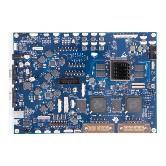
Figure 3-2 depicts the switches and connectors with their respective locations. Note that neither the cables nor the power supply are included with the module. Figure 3-2. DLPDLCR660TEVM Test Points and Connectors DLPU077 – March 2019 Connections Submit Documentation Feedback... -
Page 26: 3.2.1 Connectors
NOTE: (*) - These signals are not internally connected in the DMD 3.2.2 TestPoints 1. J1 - Flex Cable Connector 2. J2 - Flex Cable Connector 3. J4 - DMD_P3P3V Connections DLPU077 – March 2019 Submit Documentation Feedback Copyright © 2019, Texas Instruments Incorporated... -
Page 27: Power Supply Requirements
TI’s required minimum electrical ratings in addition to complying with applicable regional product regulatory and safety certification requirements such as (by example) UL, CSA, VDE, CCC, PSE, and so forth. DLPU077 – March 2019 Power Supply Requirements Submit Documentation Feedback Copyright © 2019, Texas Instruments Incorporated... -
Page 28: Safety
Caution Labels CAUTION The kit contains ESD-sensitive components. Handle with care to prevent permanent damage. If You Need Assistance Refer to the DLP E2E Community support forums. Safety DLPU077 – March 2019 Submit Documentation Feedback Copyright © 2019, Texas Instruments Incorporated... - Page 29 STANDARD TERMS FOR EVALUATION MODULES Delivery: TI delivers TI evaluation boards, kits, or modules, including any accompanying demonstration software, components, and/or documentation which may be provided together or separately (collectively, an “EVM” or “EVMs”) to the User (“User”) in accordance with the terms set forth herein.
- Page 30 www.ti.com Regulatory Notices: 3.1 United States 3.1.1 Notice applicable to EVMs not FCC-Approved: FCC NOTICE: This kit is designed to allow product developers to evaluate electronic components, circuitry, or software associated with the kit to determine whether to incorporate such items in a finished product and software developers to write software applications for use with the end product.
- Page 31 www.ti.com Concernant les EVMs avec antennes détachables Conformément à la réglementation d'Industrie Canada, le présent émetteur radio peut fonctionner avec une antenne d'un type et d'un gain maximal (ou inférieur) approuvé pour l'émetteur par Industrie Canada. Dans le but de réduire les risques de brouillage radioélectrique à...
- Page 32 www.ti.com EVM Use Restrictions and Warnings: 4.1 EVMS ARE NOT FOR USE IN FUNCTIONAL SAFETY AND/OR SAFETY CRITICAL EVALUATIONS, INCLUDING BUT NOT LIMITED TO EVALUATIONS OF LIFE SUPPORT APPLICATIONS. 4.2 User must read and apply the user guide and other available documentation provided by TI regarding the EVM prior to handling or using the EVM, including without limitation any warning or restriction notices.
- Page 33 Notwithstanding the foregoing, any judgment may be enforced in any United States or foreign court, and TI may seek injunctive relief in any United States or foreign court. Mailing Address: Texas Instruments, Post Office Box 655303, Dallas, Texas 75265 Copyright © 2019, Texas Instruments Incorporated...
- Page 34 TI products. TI’s provision of these resources does not expand or otherwise alter TI’s applicable warranties or warranty disclaimers for TI products. Mailing Address: Texas Instruments, Post Office Box 655303, Dallas, Texas 75265 Copyright © 2019, Texas Instruments Incorporated...