Emerson Micro Motion 5700 - Ethernet Transmitters Manual
- Configuration and use manual (357 pages) ,
- Instruction manual (58 pages) ,
- Installation manual (56 pages)
- 1 Before you begin
- 2 Planning
-
3
Mounting and sensor wiring
- 3.1 Mounting and sensor wiring for integral-mount transmitters
- 3.2 Mounting transmitters
- 3.3 Wire a remote-mount transmitter to the sensor
- 3.4 Ground the meter components
- 3.5 Rotate the transmitter on the sensor (optional)
- 3.6 Rotate the user interface on the transmitter (optional)
- 3.7 Rotate the sensor wiring junction box on a remote-mount transmitter (optional)
- 4 Wiring the channels
- 5 Power supply wiring
- 6 Set up the printer
- 7 Power up the transmitter
- 8 Guided setup
- 9 Using the display controls
- 10 Available service port connection
- 11 A: Wire the 5700 to the 3100 relays
- 12 Safety messages
- 13 Documents / Resources
![]()
Before you begin
About this document
This manual provides information on planning, mounting, wiring, and initial setup of the Micro Motion transmitter. For information on full configuration, maintenance, troubleshooting, or service of the transmitter, see the Micro Motion 5700 with Ethernet Transmitters: Configuration and Use Manual.
The information in this document assumes that users understand basic transmitter and sensor installation, configuration, and maintenance concepts and procedures.
Hazard messages
This document uses the following criteria for hazard messages based on ANSI standards Z535.6-2011 (R2017).

Serious injury or death will occur if a hazardous situation is not avoided.

Serious injury or death could occur if a hazardous situation is not avoided.

Minor or moderate injury will or could occur if a hazardous situation is not avoided.
 NOTICE
Data loss, property damage, hardware damage, or software damage can occur if a situation is not avoided. There is no credible risk of physical injury.
Physical access
Unauthorized personnel can potentially cause significant damage and/or misconfiguration of end users' equipment. Protect against all intentional or unintentional unauthorized use.
Physical security is an important part of any security program and fundamental to protecting your system. Restrict physical access to protect users' assets. This is true for all systems used within the facility.
Related documentation
You can find all product documentation on the product documentation DVD shipped with the product or at Emerson.com.
See any of the following documents for more information:
- Micro Motion 5700 Transmitters Product Data Sheet
- Micro Motion 5700 with Ethernet Transmitters: Configuration and Use Manual
- Micro Motion 5700 Transmitters: EtherNet/IP Rockwell RSLogix Integration Guide
- Micro Motion 5700 Transmitters: PROFINET Siemens PLC Integration Guide
- Sensor installation manual
Planning
Installation checklist
- If possible, install the transmitter in a location that will prevent direct exposure to sunlight. The environmental limits for the transmitter may be further restricted by hazardous area approvals.
- If you plan to mount the transmitter in a hazardous area:
- Verify that the transmitter has the appropriate hazardous area approval. Each transmitter has a hazardous area approval tag attached to the transmitter housing.
- Ensure that any cable used between the transmitter and the sensor meets the hazardous area requirements.
- For ATEX/IECEx installations, strictly adhere to the safety instructions documented in the ATEX/IECEx approvals documentation available on the product documentation DVD shipped with the product or at Emerson.com.
- Ensure that you use the following cables for the different connections:
- twisted-pair instrument cable for the Channel I/O connection
- shielded Cat5E or higher rated instrumentation cable for the Ethernet connections
- You can mount the transmitter in any orientation as long as the conduit openings do not point upward.
Installing the transmitter with the conduit openings facing upward risks condensation moisture entering the transmitter housing, which could damage the transmitter. Following are examples of possible orientations for the transmitter.
| Preferred orientation | Alternate orientations | |
 |  |  |
- Any fittings, adapters, or blanking elements used on either conduit entries or threaded joints that are a part of flame proof joints must comply with the requirements of EN/IEC 60079-1 & 60079-14 or CSA C22.2 No 30 & UL 1203 for Europe/International and North America respectively.
Only qualified personnel can select and install these elements in accordance with EN/IEC 60079-14 for ATEX/IECEx or to NEC/CEC for North America. - To maintain the Ingress protection thread sealant, a sealing washer, or O-ring must be applied:
- Mount the meter in a location and orientation that satisfies the following conditions:
Additional considerations for retrofitting existing installations
- Before removing the existing transmitter, be sure to record the configuration data for the currently installed transmitter. At initial startup of the newly installed transmitter, you will be prompted to configure the meter via a guided setup.
Record the following information (if applicable):
| Variable | Setting |
| Tag | |
| Mass flow units | |
| Volume flow units | |
| Density units | |
| Temperature units | |
| Channel configuration | |
| mA Output 1 | |
| mA Output 2 (optional) |
|
| Variable | Setting |
| Frequency output (optional) |
|
| Discrete output (optional) |
|
| Discrete input (optional) |
|
| Calibration parameters (for 9-wire installations only) | |
| Flow calibration factor | FCF (Flow cal or flow calibration factor): |
| Density calibration factors |
|
Power requirements
Self-switching AC/DC input, automatically recognizes supply voltage:
- 85 to 240 VAC, 6.5 watts typical, 9 watts maximum
- 18 to 100 VDC, 6.5 watts typical, 9 watts maximum
Note
For DC power:
- Power requirements assume a single transmitter per cable.
- At start-up, the power source must provide a minimum of 1.5 amps of short-term current per transmitter and not pull voltage below 18 VDC.
- Length and conductor diameter of the power cable must be sized to provide 18 VDC minimum at the power terminals, at a load current of 0.7 amps.
Cable sizing formula
M = 18V + (R x L x 0.7A)
- M: minimum supply voltage
- R: cable resistance
- L: cable length (in Ω/ft)
Typical power cable resistance at 68°F (20.0°C)
| Wire gauge | Resistance |
| 14 AWG | 0.0050 Ω/ft |
| 16 AWG | 0.0080 Ω/ft |
| 18 AWG | 0.0128 Ω/ft |
| 20 AWG | 0.0204 Ω/ft |
| 2.5 mm2 | 0.0136 Ω/m |
| 1.5 mm2 | 0.0228 Ω/m |
| 1.0 mm2 | 0.0340 Ω/m |
| 0.75 mm2 | 0.0460 Ω/m |
| 0.50 mm2 | 0.0680 Ω/m |
Maximum cable lengths between sensor and transmitter
The maximum cable length between the sensor and transmitter, which are installed separately, is determined by cable type.
| Cable type | Wire gauge | Maximum length |
| Micro Motion 4-wire remote mount | Not applicable |
|
| Micro Motion 9-wire remote mount | Not applicable | 1,000 ft (305 m)(1) |
| User-supplied 4-wire | VDC 22 AWG (0.326 mm²) | 300 ft (91 m) |
| VDC 20 AWG (0.518 mm²) | 500 ft (152 m) | |
| VDC 18 AWG (0.823 mm²) | 1,000 ft (305 m) | |
| RS-485 22 AWG (0.326 mm²) or larger | 1,000 ft (305 m) |
(1) For Smart Meter Verification, the limit is 60 ft (18 m).
5700 transmitters in Ethernet networks
You can install the 5700 Ethernet transmitter in star, ring, or daisy-chain networks using industrial-rated shielded Ethernet cables.
- Make sure that each cable is no longer than 328 ft (100 m).
- Connect the 5700 Ethernet transmitter to the host system via a LAN (Local Area Network) and not a WAN (Wide Area Network).
- Follow all network security best practices.
Star topology
5700 Ethernet transmitters can be installed in a star network
Figure 1: 5700 star network

- Programmable Logic Controller (PLC)
- 5700 with Ethernet output
- External Ethernet switch
Note
The External Ethernet switch must be a managed switch capable of Spanning Tree Protocol (STP) or similar functions.
Ring topology
5700 Ethernet transmitters can be installed in a ring network.
Figure 2: 5700 ring network

- Programmable Logic Controller (PLC)
- 5700 with Ethernet output
Note
The PLC must be a managed switch capable of Spannng Tree Protocol (STP) or similar functions.
Daisy-chain topology
5700 Ethernet transmitters can be installed in a daisy-chain network.
Figure 3: 5700 daisy-chain network

- Programmable Logic Controller (PLC)
- 5700 with Ethernet output
Mounting and sensor wiring
Mounting and sensor wiring for integral-mount transmitters
There are no separate mounting requirements for integral transmitters, and there is no need to connect wiring between the transmitter and the sensor.
Mounting transmitters
There are two options available for mounting 5700 transmitters:
- Mount the transmitter to a wall or flat surface.
- Mount the transmitter to an instrument pole.
Mount the transmitter to a wall or flat surface
Prerequisites
- Emerson recommends 5/16-18 (M8X1.25) fasteners that can withstand the process environment. Emerson does not supply bolts or nuts as part of the standard offering (general purpose bolts and nuts are available as an option).
- Ensure that the surface is flat and rigid and that it does not vibrate or move excessively.
- Confirm that you have the necessary tools and the mounting kit shipped with the transmitter.
- Confirm that the mounting surface, method, and surface structure ensures sufficient strength to secure the transmitter (e.g. when mounting to drywall use a toggle type drywall anchor).
Procedure
- Attach the mounting bracket to the transmitter and tighten the screws to 80 in lbf (9.04 N m) to 90 in lbf (10.17 N m).
Figure 4: Mounting bracket to an aluminum transmitter
![]()
Figure 5: Mounting bracket to a stainless steel transmitter

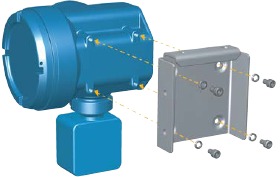

Figure 6: Wall-mounting bracket and dimensions for an aluminum transmitter
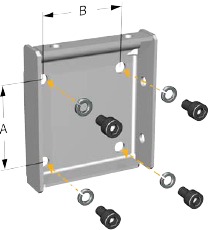
- 2.8 in (71 mm)
- 2.8 in (71 mm)
Figure 7: Wall-mounting bracket and dimensions for a stainless steel transmitter

- 7.51 in (190.8 mm)
- 3.67 in (93.2 mm)
- For aluminum transmitters, place and attach the transmitter-mounting bracket to the mounting bracket secured to the wall or instrument pole.
Figure 8: Attaching and securing an aluminum transmitter to the mounting bracket
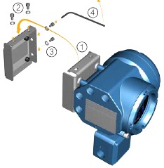
 Tip
Tip
To ensure the mounting bracket holes are aligned, insert all attachment bolts into place before tightening.
Mount the transmitter to a pole
Prerequisites
- Ensure that the instrument pole extends at least 12 in (305 mm) from a rigid base and is no more than 2 in (51 mm) in diameter.
- Confirm that you have the necessary tools, and the instrument-pole mounting kit shipped with the transmitter.
Procedure
For pole-mount installations, fit the U-bolt mounting piece to the instrument pole.
Figure 9: Pole-mounting bracket attachment for an aluminum transmitter

Figure 10: Pole-mounting bracket attachment for a stainless steel transmitter

Wire a remote-mount transmitter to the sensor
Use this procedure to wire a 4-wire or 9-wire remote-mount transmitter to the sensor.
Prerequisites
- Prepare the 9-wire cable as described in the Micro Motion 9-Wire Flow Meter Cable Preparation and Installation Guide.
- Connect the cable to the sensor-mounted core processor or junction box as described in the sensor documentation. You can access all product documentation on the documentation DVD shipped with the product or at Emerson.com.
Procedure
- Remove the transmitter-to-sensor wiring compartment cover to reveal the terminal connections.
Figure 11: Removal of the transmitter-to-sensor wiring compartment cover
![]()
- Feed the sensor wiring cable into the transmitter wiring compartment.
Figure 12: Sensor wiring feedthrough


Terminate the 4-wire cable drain wires only at the sensor/core processor end of the cable. See the sensor installation manual for more detail. Do not connect the 4-wire cable drain wires to the ground screw located inside the junction box.
Figure 13: 4-wire transmitter-to-sensor wiring connections

Figure 14: 9-wire transmitter-to-sensor wiring connections

Note
Connect the four drain wires in the 9-wire cable to the ground screw located inside the junction box.
- Replace the transmitter-to-sensor wiring compartment cover and tighten the screwsto 14 in lbf (1.58 N m) to 15 in lbf (1.69 N m).
Ground the meter components
In 4-wire or 9-wire remote installations, the transmitter and sensor are grounded separately.
Prerequisites
NOTICE
Improper grounding could cause inaccurate measurements or meter failure.
Improper grounding could result in an explosion causing death or serious injury.
Note
For hazardous area installations in Europe, refer to standard EN 60079-14 or national standards.
If national standards are not in effect, adhere to the following guidelines for grounding:
- Use copper wire, 14 AWG (2.08 mm2) or larger wire size.
- Keep all ground leads as short as possible, less than 1 Ω impedance.
- Connect ground leads directly to earth, or follow plant standards.
Procedure
- Ground the Coriolis sensor according to the instructions in the sensor installation manual for your Coriolis sensor.
- Ground the transmitter according to applicable local standards, using thetransmitter's internal or external ground screw.
- The internal ground screw is located inside the transmitter-to-sensor wiring compartment.
Figure 15: Internal ground screw
- The earth ground terminal is located inside the power wiring compartment.
- The external ground screw is located on the outside of the transmitter housing below the transmitter tag.
Figure 16: External ground screw
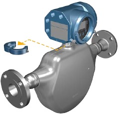
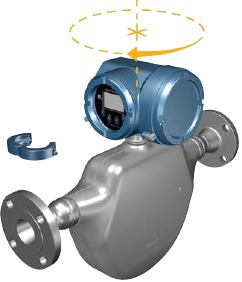
Rotate the transmitter on the sensor (optional)
In integral installations, you can rotate the transmitter on the sensor up to 360° in 45° increments.
Procedure
- Using a 4 mm hex key, loosen and remove the clamp securing the transmitter head in place.
Figure 17: Removal of the sensor clamp
![]()
Over rotating the housing can lead to damaging the feedthrough cable.
Figure 18: Rotate transmitter head
- Gently lower the transmitter onto the base, confirming that the transmitter is in alocked position.
- Replace the clamp in its original position and tighten the cap screw. Torque to 28 in lbf (3.16 N m) to 30 in lbf (3.39 N m).
Figure 19: Re-attachment of the sensor clamp

Rotate the user interface on the transmitter (optional)
The user interface on the transmitter electronics module can be rotated 90°, 180°, or 270° from the original position.
Figure 20: Display components
")
- Transmitter housing
- Sub-bezel
- Display module
- Display screws
- End-cap clamp
- Cap screw
- Display cover
Procedure
- Shut off power to the unit.
![]()
If the transmitter is in a hazardous area, wait five minutes after disconnecting the power. Failure to do so could result in an explosion causing death or injury. - Loosen and rotate the end-cap clamp so that it does not interfere with the cover.
- Turn the display cover counterclockwise to remove it from the main enclosure.
- Carefully loosen the captive display screws while holding the display module inplace.
- Carefully pull the display module out of the main enclosure.
- Rotate the display module to the desired position.
- Gently press the display module back onto the connector.
- Tighten display screws.
- Place the display cover onto the main enclosure.
- Turn the display cover clockwise until it is fully seated.
- Replace the end-cap clamp by tightening the cap screw.
- Restore power to the transmitter.
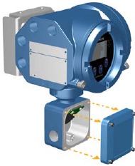
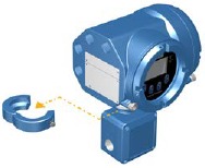
Rotate the sensor wiring junction box on a remote-mount transmitter (optional)
In remote-mount installations, you can rotate the sensor wiring junction box on the transmitter plus or minus 180º.
Procedure
- Using a 4 mm hex key, loosen and remove the clamp securing the sensor wiring junction box in place.
Figure 21: Removal of the clamp
![]()
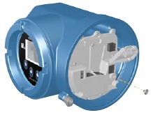
- Gently rotate the junction box to the desired position. You can rotate the junction box plus or minus 180° to any position.
Figure 22: Rotate the transmitter on the junction box
![]()
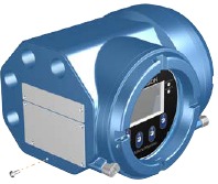
- Gently set the junction box into its new position, confirming that the position islocked.
- Replace the clamp in its original position and tighten the cap screw. Torque to 28 in lbf (3.16 N m) to 30 in lbf (3.39 N m).
Figure 23: Re-attach the clamp
![]()


Wiring the channels
Available channels
| Signal | Channel A | Channel B | Channel C |
| Channel options | EtherNet/IP™ The same protocol must be ordered on both Channel A and B. ProLink™ III and the Integrated Web server can always be connected to either Channel A or B. | EtherNet/IP | mA output |
| Modbus™ TCP | Modbus TCP | Frequency output | |
| PROFINET® | PROFINET | Discrete output | |
| N/A | N/A | Discrete input |
Wire the I/O channel
The Channel 5700 I/O can be configured as:
- mA Output
- Frequency Output
- Discrete Output
- Discrete Input
Access the wiring channels
Procedure
Remove the wiring access cover to reveal the I/O wiring terminal block connectors.
Figure 24:

Wire the mA Output
Wire the mA Output for explosion-proof, nonincendive, or nonhazardous installations.
Prerequisites
Meter installation and wiring should be performed only by suitably-trained personnel using the appropriate government and corporate safety standards.
Procedure
Wire to the appropriate output terminal and pins.
Figure 25: Internally-powered mA Output wiring

- mA Output
- Channel
- 820 Ω maximum loop resistance
![warning]() Note
Note
This resistor is normally built into the signal device (d). This resistor is not used for HART® communications. - Signal device
Figure 26: Externally-powered mA Output wiring
A 
- mA Output
- Channel
- 5–30 VDC (maximum)
- See Figure 27
- Signal device
Figure 27: Externally-powered mA Output: maximum loop resistance

- Maximum resistance (Ω)
- External supply voltage (V)
Wire the Frequency Output
Wire the Frequency Output in explosion-proof, nonincendive, or nonhazardous installations.
Prerequisites
Meter installation and wiring should be performed only by suitably-trained personnel using the appropriate government and corporate safety standards.
Procedure
Wire to the appropriate output terminal and pins.
Figure 28: Internally-powered FO wiring

- Frequency Output
- Channel
- See Figure 29
- Counter
Figure 29: Internally-powered FO: output amplitude versus load resistance [24 VDC (Nom) open circuit]

- Output amplitude (V)
- Load resistor (Ω)
Figure 30: Externally-powered FO wiring

- Frequency Output
- Channel
- 5–30 VDC (maximum)
- 500 mA current (maximum)
- Counter
Wire the Discrete Output
Wire the Discrete Output in explosion-proof, nonincendive, or nonhazardous installations.
Prerequisites
Meter installation and wiring should be performed only by suitably-trained personnel using the appropriate government and corporate safety standards.
Procedure
Wire to the appropriate output terminal and pins.
Figure 31: Internally-powered DO wiring

- Discrete Output
- Channel
- See Figure 32
- Counter
Figure 32: Internally-powered DO: output amplitude versus load resistance [24 VDC (Nom) open circuit]

- Output amplitude (V)
- Load resistor (Ω)
Figure 33: Externally-powered DO wiring

- Discrete Output
- Channel
- 3–30 VDC (maximum)
- 500 mA current (maximum)
- Counter
Wire the Discrete Input
Prerequisites
Wire the Discrete Input in explosion-proof, nonincendive, or nonhazardous installations.
Meter installation and wiring should be performed only by suitably-trained personnel using the appropriate government and corporate safety standards.
Procedure
Wire to the appropriate input terminal and pins.
Figure 34: Internally-powered DI wiring

- Discrete Input
- Channel C
- Switch
Figure 35: Externally-powered DI wiring

- Discrete Input
- Channel C
- 30 VDC (maximum)
Note
- Maximum positive threshold is 3 VDC.
- Minimum negative threshold is 0.6 VDC.
Wire the I/O channel using an M12-terminated cable (optional)
Use this procedure if you are using an M12-terminated cable to wire the I/O channel.
Prerequisites
Obtain an A-coded M12-terminated cable.
Procedure
- Attach the M12-terminated cable to the configuration I/O connector on the 5700 transmitter.
Figure 36: M12-terminated cables to the configuration I/O

- Attach the other cable end using the pinouts described in the following table.
Table 1: M12 configuration I/O pinouts

| Pin identification | Wire color | Outputs |
| Pin 1 | Not used | Not used |
| Pin 2 | White | Positive terminal |
| Pin 3 | Not used | Not used |
| Pin 4 | Black | Neutral terminal |
Wire the Ethernet channels
To meet the EC Directive for Electromagnetic Compatibility (EMC), use a suitable shielded Cat5e, or higher-rated instrumentation cable to connect the meter. The instrumentation cable should have an overall screen to cover all cores. Where permissible, connect the overall screen to earth at the host end (360° bonded).
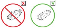
Wire an Ethernet network using the RJ45 ports
Prerequisites
When using a pre-terminated RJ45 cable, ensure there is no protective boot on the connector, as a protective boot will not fit through the conduit. Alternatively, you can use the RJ45 connector using a shielded-field termination connector.
Direct connection and star topology
Procedure
- Feed the RJ45 cable through the conduit on the 5700 transmitter.
- Connect the RJ45 cable into either Channel A or Channel B.
Functionality is identical for both Channel A and Channel B as the 5700 transmitter contains an internal Ethernet switch. - Anchor the cable to the module backplate using a cable tie.
Example
Daisy-chain and ring topologies
Procedure
- Feed two RJ45 cables through the conduits on the 5700 transmitter.
Since two cables will not fit into one conduit, you will need to use separate conduits for each cable. - Connect the external switch or previous transmitter to Channel A or Channel B.
Functionality is identical for both Channel A and Channel B as the 5700 transmitter contains an internal Ethernet switch. - Connect the next transmitter in the network to the unused channel.
- Anchor the cables to the module backplate using cable ties.
Example

Wire the Ethernet I/O using M12-terminated cables (optional)
Prerequisites
Obtain two D-coded M12-terminated Ethernet cables.
Procedure
- Attach both M12-terminated Ethernet cables to the Ethernet I/O connectors on the 5700 transmitter. See Figure 37.
- Attach the other cable end using the pinouts described in Table 2.
Figure 37: M12 cables to the Ethernet I/O
")
Note
Depending on what type of M12 Ethernet option you have, your transmitter may have only the two Ethernet I/O connectors.
Table 2: M12 Ethernet I/O pinouts
| Pin identification | Wire color | Outputs on RJ45 | Signal name |
| Pin 1 | Orange/White | Pin 1 | TDP1/RDP2 |
| Pin 2 | Green/White | Pin 3 | RDP1/TDP2 |
| Pin 3 | Orange | Pin 2 | TDN1/RDN2 |
| Pin 4 | Green | Pin 6 | RDN1/RDN2 |
Power supply wiring
Wiring the power supply
You can install a user-supplied switch in the power supply line.
For compliance with the Low Voltage Directive 2014/35/EU (European installations), verify that the transmitter is located in close proximity to a switch.
Procedure
- Remove the wiring access cover.
- Open the Power warning flap to locate the power terminals.
Figure 38: Location of power supply wiring terminals and equipment ground

- Power supply wiring terminals (+ and -)
- Conduit connection for power supply wiring
- Equipment ground
- Connect the power supply wires.
- For DC power: connect to terminals + and –.
- For AC power: connect to terminals L/L1 (line) and N/L2 (neutral).
NOTICE
Do not use the conduit specified for power supply wires for input/output wiring (see Figure 38) to avoid pinched wires when the cover is closed.
- Tighten the two screws holding the power connector in place.
- Ground the power supply using the equipment ground, also under the Power warning flap.
Wire the power supply using an M12-terminated cable (optional)
Use this procedure if you are using an M12-terminated cable to wire the power supply.
Prerequisites
Obtain an S-coded M12-terminated cable.
Procedure
- Attach the M12-terminated cable to the power connector on the 5700 transmitter.
- Attach the other cable end using the pinouts described in Table 3.
Figure 39: M12-terminated cable to power supply

Note
For M12 power supply pinouts, only pins 1 and 3 are used.
Table 3: M12 power supply pinouts
| Pin identification | Wire color | Outputs on board | Signal name |
| Pin 1 | Brown | Terminal 3 | VDC + |
| Pin 2 | White | Terminal 1 | Channel B + |
| Pin 3 | Blue | Terminal 4 | VDC - |
| Pin 4 | Black | Terminal 2 | Channel B - |
Set up the printer
Use this section to set up printing with a 5700 Ethernet transmitter and an Epson TM-T88VI Ethernet printer. For information on configuring the printer, see Micro Motion 5700 with Ethernet Transmitters: Configuration and Use Manual.
There are two ways to set up printing:
- Use the printer's default IP address
- Change the printer's default IP address
Set up the printer by changing the printer default IP address
Use this procedure to set up printing with a 5700 Ethernet transmitter and an Epson TM-T88VI printer by changing the printer's default IP address.
Procedure
- Connect one end of an Ethernet cable and power supply to the printer.
- Connect the other end of the Ethernet cable to the PC.
- Power on the printer. The printer IP address prints after a few minutes.
- Temporarily change the Ethernet address for the PC so that the Ethernet is on thesame subnet as the printer:
Default IP address = 192.168.192.168- From Windows 10, right-click the Start button and select Network Connections.
- Right-click the Ethernet connection and select Properties.
Select Yes on any user account pop-up windows. - Select Internet Protocol Version 4 (TCP/IPv4), then select Properties.
- Select Use the following IP address and configure the IP address and subnet mask as follows:
- IP address: 192.168.192.x, where x is something other than 0, 1, or 168
- Subnet mask: 255.255.255.0
- Select OK.
- Change the printer firmware options.
- Open your web browser and type http://192.168.192.168 (default printer IP).
The browser displays, Your connection is not private. Ignore the warning and proceed to the website. - Select ADVANCED.
- Select Proceed to 192.168.192.168.
- At the login screen, enter:
Default username: epson
Default password: epson
The EpsonNet Config utility screen displays. - Select TCP/IP under the configuration settings (not the basic settings), listed on the left side of the screen.
- Change the IP Address (i.e., 192.168.1.55), Subnet Mask, and Default Gateway based on your network. Select an IP address that is unique to the local network. The printer must be on the same subnet as the 5700.
- Required: Set Acquiring the IP Address to Manual.
- Select Send to save your settings.
- Select Reset, or power cycle the printer when prompted to apply the changes.
- Open your web browser and type http://192.168.192.168 (default printer IP).
- Change the PC network settings back to the original settings. Use the windows you used in Step 4.
- Configure the 5700 Ethernet transmitter for the printer.
- Remove the Ethernet cable from the PC and connect it to the 5700 Ethernettransmitter.
- If you have not already done so, configure the transmitter IP address, subnetmask, and default gateway.
| Display | Menu → Configuration → Ethernet Settings → Network Settings |
| ProLink III | Device Tools → Configuration → Network Settings |
For instructions on how to configure the transmitter and PC Ethernet settings, see the Micro Motion 5700 with Ethernet Transmitters: Configuration and Use Manual.
- Enter the printer IP address you configured in the previous step into the 5700 Ethernet transmitter.
| Display | Menu → Configuration → Printer → Printer IP address |
| ProLink III | Device Tools → Configuration → Printer and Tickets |
| Web browser | Configuration → Printer and Tickets |
- Perform a test print to verify the settings are correct.
| Display | Menu → Operations → Printer → Print Ticket → Print Test Page |
| ProLink III | Device Tools → Configuration → Printer and Tickets |
| Web browser | Configuration → Printer and Tickets |
For instructions on how to configure print ticket options, see the Micro Motion 5700 with Ethernet Transmitters: Configuration and Use Manual.
If needed, see Function Check Failed in the Status alerts, causes, and recommendations section of the Micro Motion 5700 with Ethernet Transmitters: Configuration and Use Manual.
Set up the printer using the printer default IP address
Use this procedure to set up printing with a 5700 Ethernet transmitter and an Epson TM-T88VI printer using the printer's default IP address.
Procedure
- Connect one end of an Ethernet cable and power supply to the printer.
- Connect the other end of the Ethernet cable to the PC.
- Power on the printer.
It can take 1-2 minutes for the printer to finish configuring network settings. When complete, the following ticket prints.
IP Address: 192.168.192.168
SubnetMask: 255.255.255.0
Gateway: 0.0.0.0 DHCP: No server - > Static
- Turn off DHCP if it is enabled.
| From the display | From ProLink III |
|
|
- Configure the IP address.
- Navigate to one of the following screens:
| From the display | From ProLink III |
| Go to Menu → Configuration → Ethernet Settings → Network Settings → IP address. | Go to Device Tools → Configuration → Network Settings. |
- Set the IP address to 192.168.192.x, where x is something other than 0, 1, or 168.
- Configure the subnet mask.
- Navigate to one of the following screens:
| From the display | From ProLink III |
| Go to Menu → Configuration → Ethernet Settings → Network Settings → Subnet Mask. | Go to Device Tools → Configuration → Network Settings. |
- Set the subnet mask to 255.255.255.0.
- Configure the printer type.
- Navigate to one of the following screens:
| From the display | From ProLink III |
| Go to Menu → Configuration → Printer → Printer Type. | Go to Device Tools → Configuration → Printer and Tickets. |
- Verify that the IP address is 192.168.192.168.
Reset the interface settings
Use this procedure if you forgot the IP address of your printer and need to reset the default (192.168.192.168).
Procedure
- Turn off the printer and close the roll paper cover.
- If the connector cover is attached, remove the cover.
- Hold down the status sheet button on the back of the printer while turning on theprinter.
A message displays indicating that resetting is being performed. - Release the status sheet button to reset the printer settings to default.
Do not turn off power until the process is complete.
When complete, a Resetting to Factory Default Finished message displays.
Function Check Failed
A functional check alert is commonly triggered due to the following conditions:
- Incorrect network settings configuration
- Out of paper
- Paper tray is open
- Printer already has six open connections
- Another transmitter tries to start a print while another transmitter is printing configuration items and audit log tickets can take more than 15 minutes to print and use up paper. If during this time another transmitter starts a print, the new print may either be rejected, causing a functional check alert (printer offline), or the print will be inserted in the middle of the configuration/audit log print.
The functional check alert is cleared after a successful print.
Power up the transmitter
The transmitter must be powered up for all configuration and commissioning tasks, or for process measurement.
Procedure
![]()
If the transmitter is in a hazardous area, do not remove the housing cover while the transmitter is powered up. Failure to follow these instructions can cause an explosion resulting in injury or death.
Ensure that all transmitter and sensor covers and seals are closed.- Turn on the electrical power at the power supply.
The transmitter will automatically perform diagnostic routines. The transmitter is self-switching and will automatically detect the supply voltage. When using DC power, a minimum of 1.5 amps of startup current is required. During this period, Alert 009 is active. The diagnostic routines should complete in approximately 30 seconds. The status LED will turn green and begin to flash when the startup diagnostics are complete. If the status LED exhibits different behavior, an alert is active.
Postrequisites
Although the sensor is ready to receive process fluid shortly after power-up, the electronics can take up to ten minutes to reach thermal equilibrium. Therefore, if this is the initial startup, or if power has been off long enough to allow components to reach ambient temperature, allow the electronics to warm up for approximately ten minutes before relying on process measurements. During this warm-up period, you may observe minor measurement instability or inaccuracy.
Guided setup
At initial startup of the transmitter, the guided configuration screen appears on the transmitter display. This tool guides you through basic configuration of the transmitter. The guided setup allows you to upload configuration files, set the transmitter display options, configure channels, and review sensor calibration data.
Using the display controls
The transmitter display interface includes a display (LCD panel) and four optical switches – left, up, down, and right arrow keys – used to access the display menus and navigate the display screens.
Procedure
- To activate an optical switch, block the light by holding your thumb or finger in front of the opening.
You can activate the optical switch through the lens. Do not remove the transmitter housing cover.
The transmitter only detects one switch selection at a time. Be sure to place your thumb or finger directly over a single optical switch, and ensure no other switches are being obstructed.
Figure 40: Proper finger positioning for activating an optical switch

- Use the arrow indicators on the display screen to identify which optical switch to useto navigate the screen (see examples 1 and 2 on the following page).
When using the arrow keys, you must first activate the optical switch then release the same switch by removing your finger from the glass to move up, down, right, left or to make a selection. To enable auto-scroll when navigating up or down, activate the appropriate switch and continue to hold for one second. Release the switch when the desired selection is highlighted.
Figure 41: Example 1: Active arrow indicators on the transmitter display

Figure 42: Example 2: Active arrow indicators on the transmitter display

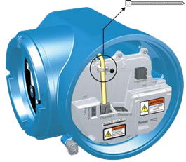
Available service port connection
Use the service port connection to download or upload data from/to the transmitter. To access the service port, you can use commonly-available USB hardware, such as a USB drive, or USB cable.
If the transmitter is in a hazardous area, do not remove the housing cover while the transmitter is powered up. Failure to follow these instructions can cause an explosion resulting in injury or death.

The service port connection is located under the transmitter cap.
A: Wire the 5700 to the 3100 relays
Use this procedure to wire the Discrete Output on the 5700 Ethernet transmitter to the 3100 transmitter relays for single-stage batch control.
Prerequisites
- Set up the Channel configuration to DO before wiring.
- Use active high and internal power.
- Use wire size 24 AWG (0.205 mm2) to 16 AWG (1.31 mm2).
Procedure
- Wire the negative terminal on Channel from the 5700 Ethernet transmitter to A14.
- Wire the positive terminal on Channel from the 5700 Ethernet transmitter to eitherC14, C16, or C18.
Figure 43: Wiring for 5700 Ethernet Channel DO to 3100 relays

For more information: Emerson.com/global
Safety messages
Safety messages are provided throughout this manual to protect personnel and equipment. Read each safety message carefully before proceeding to the next step.
Safety and approval information
This Micro Motion product complies with all applicable European directives when properly installed in accordance with the instructions in this manual. Refer to the EU Declaration of Conformity for directives that apply to this product. The following are available: the EU Declaration of Conformity, with all applicable European directives, and the complete ATEX installation drawings and instructions. In addition, the IECEx installation instructions for installations outside of the European Union and the CSA installation instructions for installations in North America are available at Emerson.com or through your local Micro Motion support center.
Information affixed to equipment that complies with the Pressure Equipment Directive, can be found at Emerson.com. For hazardous installations in Europe, refer to standard EN 60079-14 if national standards do not apply.
Other information
Troubleshooting information can be found in the appropriate Configuration and Use Manual.

Documents / Resources
References
![www.emerson.com]() https://www.emerson.com
https://www.emerson.com![www.emerson.com]() https://www.emerson.com/documents/automation/product-data-sheet-micro-motion-5700-transmitters-mvd-technology-en-66594.pdf
https://www.emerson.com/documents/automation/product-data-sheet-micro-motion-5700-transmitters-mvd-technology-en-66594.pdf![www.emerson.com]() https://www.emerson.com/documents/automation/manual-model-5700-ethernet-transmitter-configuration-use-manual-micro-motion-en-66896.pdf
https://www.emerson.com/documents/automation/manual-model-5700-ethernet-transmitter-configuration-use-manual-micro-motion-en-66896.pdf![www.emerson.com]() https://www.emerson.com/documents/automation/integration-guide-micro-motion-5700-transmitters-ethernet-ip-rockwell-rslogix-en-66892.pdf
https://www.emerson.com/documents/automation/integration-guide-micro-motion-5700-transmitters-ethernet-ip-rockwell-rslogix-en-66892.pdf![www.emerson.com]() https://www.emerson.com/documents/automation/integration-guide-micro-motion-5700-transmitters-profinet-siemens-plc-en-66898.pdf
https://www.emerson.com/documents/automation/integration-guide-micro-motion-5700-transmitters-profinet-siemens-plc-en-66898.pdf![www.emerson.com]() https://www.emerson.com/documents/automation/installation-manual-9-wire-cable-micro-motion-en-63346.pdf
https://www.emerson.com/documents/automation/installation-manual-9-wire-cable-micro-motion-en-63346.pdf![emerson.com]() http://emerson.com/global
http://emerson.com/global![emerson.com]() http://emerson.com
http://emerson.com
Download manual
Here you can download full pdf version of manual, it may contain additional safety instructions, warranty information, FCC rules, etc.
Thank you! Your question has been received!


Need Assistance?
Do you have a question about the Micro Motion 5700 that isn't answered in the manual? Leave your question here.