Emerson Micro Motion 5700 Installation Manual
Ethernet transmitters
Hide thumbs
Also See for Micro Motion 5700:
- Installation manual ,
- Configuration and use manual (357 pages) ,
- Instruction manual (58 pages)

Related Manuals for Emerson Micro Motion 5700


Summary of Contents for Emerson Micro Motion 5700
- Page 1 Installation Manual MMI-20029768, Rev AC March 2020 ™ Micro Motion 5700 Ethernet Transmitters Ethernet Installations...
- Page 2 Micro Motion employees. Micro Motion will not accept your returned equipment if you fail to follow Micro Motion procedures. Return procedures and forms are available on our web support site at www.emerson.com, or by phoning the Micro Motion Customer Service department.
-
Page 3: Table Of Contents
Installation Manual Contents MMI-20029768 March 2020 Contents Chapter 1 Before you begin......................5 1.1 About this document........................5 1.2 Hazard messages..........................5 1.3 Related documentation........................5 Chapter 2 Planning........................7 2.1 Installation checklist......................... 7 2.2 Additional considerations for retrofitting existing installations............8 2.3 Power requirements......................... 9 2.4 5700 transmitters in Ethernet networks.................. - Page 4 Contents Installation Manual March 2020 MMI-20029768 Micro Motion 5700 Ethernet Transmitters...
-
Page 5: Before You Begin
You can find all product documentation on the product documentation DVD shipped with the product or at www.emerson.com. See any of the following documents for more information: • Micro Motion 5700 Product Data Sheet • Micro Motion 5700 with Ethernet Transmitters: Configuration and Use Manual Installation Manual... - Page 6 Before you begin Installation Manual March 2020 MMI-20029768 • Micro Motion 5700 Transmitters Ethernet Rockwell RSLogix Integration Guide • Micro Motion Ethernet PROFINET Siemens Integration Guide • Sensor installation manual Micro Motion 5700 Ethernet Transmitters...
-
Page 7: Chapter 2 Planning
For ATEX/IECEx installations, strictly adhere to the safety instructions documented in the ATEX/IECEx approvals documentation available on the product documentation DVD shipped with the product or at www.emerson.com. □ Verify that you have the appropriate cable and required cable installation parts for your installation. -
Page 8: Additional Considerations For Retrofitting Existing Installations
Output 2 (optional) — Power (Internal or External): — Source: — Scaling (LRV, URV): — Fault Action: Frequency Output (optional) — Power (Internal or External): — Source: — Scaling (LRV, URV): — Fault Action: — Dual output: Micro Motion 5700 Ethernet Transmitters... -
Page 9: Power Requirements
Installation Manual Planning MMI-20029768 March 2020 Variable Setting Discrete Output (optional) — Power (Internal or External): — Source: — Scaling (LRV, URV): — Fault Action: Discrete Input (optional) — Power (Internal or External): — Source: — Scaling (LRV, URV): — Fault Action: Calibration parameters (for 9-wire installations only) Flow calibration factor... -
Page 10: 5700 Transmitters In Ethernet Networks
Make sure that each cable is no longer than 328 ft (99.97 m). • Connect the 5700 Ethernet transmitter to the host system via a LAN (Local Area Network) and not a WAN (Wide Area Network). • Follow all network security best practices. Micro Motion 5700 Ethernet Transmitters... - Page 11 Installation Manual Planning MMI-20029768 March 2020 2.4.1 Star topology 5700 Ethernet transmitters can be installed in a star network. Figure 2-1: 5700 star network A. Programmable Logic Controller (PLC) B. 5700 with Ethernet output C. External Ethernet switch Installation Manual...
- Page 12 Planning Installation Manual March 2020 MMI-20029768 2.4.2 Ring topology 5700 Ethernet transmitters can be installed in a ring network. Figure 2-2: 5700 ring network A. Programmable Logic Controller (PLC) B. 5700 with Ethernet output Micro Motion 5700 Ethernet Transmitters...
- Page 13 Installation Manual Planning MMI-20029768 March 2020 2.4.3 Daisy-chain topology 5700 Ethernet transmitters can be installed in a daisy-chain network. Figure 2-3: 5700 daisy-chain network A. Programmable Logic Controller (PLC) B. 5700 with Ethernet output Installation Manual...
- Page 14 Planning Installation Manual March 2020 MMI-20029768 Micro Motion 5700 Ethernet Transmitters...
-
Page 15: Mounting And Sensor Wiring
Installation Manual Mounting and sensor wiring MMI-20029768 March 2020 Mounting and sensor wiring Mounting and sensor wiring for integral- mount transmitters There are no separate mounting requirements for integral transmitters, and no need to connect wiring between the transmitter and the sensor. Mounting transmitters There are two options available for mounting transmitters: •... - Page 16 Mounting and sensor wiring Installation Manual March 2020 MMI-20029768 Figure 3-1: Mounting bracket to an aluminum transmitter Figure 3-2: Mounting bracket to a stainless steel transmitter 2. For wall-mount installations, secure the mounting bracket to the prepared surface. Micro Motion 5700 Ethernet Transmitters...
- Page 17 Installation Manual Mounting and sensor wiring MMI-20029768 March 2020 Figure 3-3: Wall-mounting bracket and dimensions for an aluminum transmitter A. 2.8 in (71 mm) B. 2.8 in (71 mm) Figure 3-4: Wall-mounting bracket and dimensions for a stainless steel transmitter A.
- Page 18 2 in (51 mm) in diameter. • Confirm that you have the necessary tools, and the instrument-pole mounting kit shipped with the transmitter. Procedure For pole-mount installations, attach the U-bolt mounting piece to the instrument pole. Micro Motion 5700 Ethernet Transmitters...
-
Page 19: Wire A Remote-Mount Transmitter To The Sensor
Installation Manual Mounting and sensor wiring MMI-20029768 March 2020 Figure 3-6: Pole-mounting bracket attachment for an aluminum transmitter Figure 3-7: Pole-mounting bracket attachment for a stainless steel transmitter Wire a remote-mount transmitter to the sensor Use this procedure to wire a 4-wire or 9-wire remote-mount transmitter to the sensor. Prerequisites •... - Page 20 Connect the cable to the sensor-mounted core processor or junction box as described in the sensor documentation. You can access all product documentation on the documentation DVD shipped with the product or at www.emerson.com. Procedure 1. Remove the transmitter-to-sensor wiring compartment cover to reveal the terminal connections.
- Page 21 Installation Manual Mounting and sensor wiring MMI-20029768 March 2020 Important Terminate the 4-wire cable drain wires only at the sensor/core processor end of the cable. See the sensor installation manual for more detail. Do not connect the 4-wire cable drain wires to the ground screw located inside the 5700 junction box. •...
-
Page 22: Ground The Meter Components
Figure 3-12: Internal ground screw • The earth ground terminal is located inside the power wiring compartment. • The external ground screw is located on the side of the transmitter located below the transmitter tag. Micro Motion 5700 Ethernet Transmitters... -
Page 23: Rotate The Transmitter On The Sensor (Optional)
Installation Manual Mounting and sensor wiring MMI-20029768 March 2020 Figure 3-13: External ground screw Rotate the transmitter on the sensor (optional) In integral installations, you can rotate the transmitter on the sensor up to 360º in 45º increments. Procedure 1. Using a 4 mm hex key, loosen and remove the clamp securing the transmitter head in place. - Page 24 4. Replace the clamp in its original position and tighten the cap screw. Torque to 28 in lbf (3.16 N m) to 30 in lbf (3.39 N m). Figure 3-16: Re-attachment of the sensor clamp Micro Motion 5700 Ethernet Transmitters...
-
Page 25: Rotate The User Interface On The Transmitter (Optional)
Installation Manual Mounting and sensor wiring MMI-20029768 March 2020 Rotate the user interface on the transmitter (optional) The user interface on the transmitter electronics module can be rotated 90°, 180°, or 270° from the original position. Figure 3-17: Display components A. -
Page 26: Rotate The Sensor Wiring Junction Box On A Remote-Mount Transmitter (Optional)
Figure 3-18: Removal of the clamp 2. Gently rotate the junction box to the desired position. You can rotate the junction box plus or minus 180º to any position. Figure 3-19: Rotation of the sensor wiring junction box Micro Motion 5700 Ethernet Transmitters... - Page 27 Installation Manual Mounting and sensor wiring MMI-20029768 March 2020 3. Gently set the junction box into its new position, confirming that the position is locked. 4. Replace the clamp in its original position and tighten the cap screw. Torque to 28 in lbf (3.16 N m) to 30 in lbf (3.39 N m).
- Page 28 Mounting and sensor wiring Installation Manual March 2020 MMI-20029768 Micro Motion 5700 Ethernet Transmitters...
-
Page 29: Wiring The Channels
Installation Manual Wiring the channels MMI-20029768 March 2020 Wiring the channels Available channels Signal Channel A Channel B Channel C Channel EtherNet/IP EtherNet/IP mA Output options The same protocol must be ordered on both Channel A and ™ B. ProLink III and the Integrated Webserver can always be connected to either Channel A or... - Page 30 B. Channel C C. 820 Ω maximum loop resistance D. Signal device Figure 4-2: Externally-powered mA Output wiring A. mA Output B. Channel C C. 5–30 VDC (maximum) D. See Figure 4-3 E. Signal device Micro Motion 5700 Ethernet Transmitters...
- Page 31 Installation Manual Wiring the channels MMI-20029768 March 2020 Figure 4-3: Externally-powered mA Output: maximum loop resistance 1100 1000 15.0 22.5 30.0 A. Maximum resistance (Ω) B. External supply voltage (V) 4.2.3 Wire the Frequency Output Wire the Frequency Output in explosion-proof, nonincendive, or nonhazardous installations.
- Page 32 Wire the Discrete Output in explosion-proof, nonincendive, or nonhazardous installations. Prerequisites Important Meter installation and wiring should be performed only by suitably-trained personnel using the appropriate government and corporate safety standards. Procedure Wire to the appropriate output terminal and pins. Micro Motion 5700 Ethernet Transmitters...
- Page 33 Installation Manual Wiring the channels MMI-20029768 March 2020 Figure 4-7: Internally-powered DO wiring A. Discrete Output B. Channel C C. See Figure 4-8 D. Counter Figure 4-8: Internally-powered DO: output amplitude versus load resistance [24 VDC (Nom) open circuit] 1500 2250 3000 A.
- Page 34 Meter installation and wiring should be performed only by suitably-trained personnel using the appropriate government and corporate safety standards. Procedure Wire to the appropriate input terminal and pins. Figure 4-10: Internally-powered DI wiring A. Discrete Input B. Channel C C. Switch Micro Motion 5700 Ethernet Transmitters...
- Page 35 Installation Manual Wiring the channels MMI-20029768 March 2020 Figure 4-11: Externally-powered DI wiring A. Discrete Input B. Channel C C. 30 VDC (maximum) Note • Maximum positive threshold is 3 VDC. • Minimum negative threshold is 0.6 VDC. 4.2.6 Wire the I/O channel using an M12-terminated cable (optional) Use this procedure if you are using an M12-terminated cable to wire the I/O channel.
-
Page 36: Wire The Ethernet Channels
2. Connect the RJ45 cable into either Channel A or Channel B. Functionality is identical for both Channel A and Channel B as the 5700 transmitter contains an internal Ethernet switch. 3. Anchor the cable to the module backplate using a cable tie. Micro Motion 5700 Ethernet Transmitters... - Page 37 Installation Manual Wiring the channels MMI-20029768 March 2020 Example 4.3.1 Daisy chain and ring topologies Procedure 1. Feed two RJ45 cables through the conduits on the 5700 transmitter. Since two cables will not fit into one conduit, you will need to use separate conduits for each cable.
- Page 38 Table 4-2: M12 Ethernet I/O pinouts Wire color Outputs on RJ45 Signal name identificati Pin 1 Orange/White Pin 1 TDP1/RDP2 Pin 2 Green/White Pin 3 RDP1/TDP2 Pin 3 Orange Pin 2 TDN1/RDN2 Pin 4 Green Pin 6 RDN1/RDN2 Micro Motion 5700 Ethernet Transmitters...
-
Page 39: Power Supply Wiring
Installation Manual Power supply wiring MMI-20029768 March 2020 Power supply wiring Wiring the power supply You can install a user-supplied switch in the power supply line. Important For compliance with the Low Voltage Directive 2014/35/EU (European installations), a switch in close proximity to the transmitter is required. Procedure 1. -
Page 40: Wire The Power Supply Using An M12-Terminated Cable (Optional)
Figure 5-2: M12-terminated cable to power supply Table 5-1: M12 power supply pinouts Pin identification Outputs Pin 1 + / L / L1 Pin 2 - / N / L2 Pin 3 Not used Ground Ring terminal (C) Micro Motion 5700 Ethernet Transmitters... -
Page 41: Set Up The Printer
Set up the printer Use this section to set up printing with a 5700 Ethernet transmitter and an Epson TM- T88VI printer. For information on configuring the printer, see Micro Motion 5700 with Ethernet Transmitters: Configuration and Use Manual. There are two ways to set up printing: •... - Page 42 Device Tools → Configuration → Network Settings For instructions on how to configure the transmitter and PC Ethernet settings, see the Micro Motion 5700 with Ethernet Transmitters: Configuration and Use Manual. c) Enter the printer IP address you configured in the previous step into the 5700 Ethernet transmitter.
-
Page 43: Set Up The Printer Using The Printer Default Ip Address
Configuration → Printer and Tickets Web browser For instructions on how to configure print ticket options, see the Micro Motion 5700 with Ethernet Transmitters: Configuration and Use Manual. If needed, see Function Check Failed in the Status alerts, causes, and recommendations section of the Micro Motion 5700 with Ethernet Transmitters: Configuration and Use Manual. -
Page 44: Reset The Interface Settings
3. Hold down the status sheet button on the back of the printer while turning on the printer. A message displays indicating that resetting is being performed. 4. Release the status sheet button to reset the printer settings to default. Important Do not turn off power until the process is complete. Micro Motion 5700 Ethernet Transmitters... -
Page 45: Function Check Failed
Installation Manual Set up the printer MMI-20029768 March 2020 When complete, a Resetting to Factory Default Finished message displays. Function Check Failed A functional check alert is commonly triggered due to the following conditions: • Incorrect network settings configuration • Out of paper •... - Page 46 Set up the printer Installation Manual March 2020 MMI-20029768 Micro Motion 5700 Ethernet Transmitters...
-
Page 47: Power Up The Transmitter
Installation Manual Power up the transmitter MMI-20029768 March 2020 Power up the transmitter The transmitter must be powered up for all configuration and commissioning tasks, or for process measurement. Procedure WARNING If the transmitter is in a hazardous area, do not remove the housing cover while the transmitter is powered up. - Page 48 Power up the transmitter Installation Manual March 2020 MMI-20029768 Micro Motion 5700 Ethernet Transmitters...
-
Page 49: Chapter 8 Guided Setup
Installation Manual Guided setup MMI-20029768 March 2020 Guided setup At initial startup of the transmitter, the guided configuration screen appears on the transmitter display. This tool guides you through basic configuration of the transmitter. The guided setup allows you to upload configuration files, set the transmitter display options, configure channels, and review sensor calibration data. - Page 50 Guided setup Installation Manual March 2020 MMI-20029768 Micro Motion 5700 Ethernet Transmitters...
-
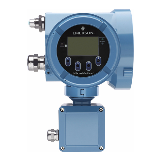
Page 51: Using The Display Controls
Installation Manual Using the display controls MMI-20029768 March 2020 Using the display controls The transmitter display interface includes a display (LCD panel) and four optical switches – left, up, down, and right arrow keys – used to access the display menus and navigate the display screens. - Page 52 Using the display controls Installation Manual March 2020 MMI-20029768 Figure 9-2: Example 1: Active arrow indicators on the transmitter display Figure 9-3: Example 2: Active arrow indicators on the transmitter display Micro Motion 5700 Ethernet Transmitters...
-
Page 53: Available Service Port Connection
Installation Manual Available service port connection MMI-20029768 March 2020 Available service port connection Use the service port connection to download or upload data from/to the transmitter. To access the service port, you can use commonly-available USB hardware, such as a USB drive, or USB cable. - Page 54 Available service port connection Installation Manual March 2020 MMI-20029768 Micro Motion 5700 Ethernet Transmitters...
-
Page 55: Appendix A 5700 To 3100 Transmitter Connections
Installation Manual 5700 to 3100 transmitter connections MMI-20029768 March 2020 5700 to 3100 transmitter connections Use this section as a reference when wiring a 5700 transmitter to a 3100 transmitter. The following graphic sets Channel B, configured as DO1, to relay 1. If a different channel is assigned to DO, wire any DO to any relay. - Page 56 © 2020 Micro Motion, Inc. All rights reserved. The Emerson logo is a trademark and service mark of Emerson Electric Co. Micro Motion, ELITE, ProLink, MVD and MVD Direct Connect marks are marks of one of the Emerson Automation Solutions family of companies. All other marks are property of their respective owners.