
Related Manuals for Emerson Copeland OME-16T


Summary of Contents for Emerson Copeland OME-16T
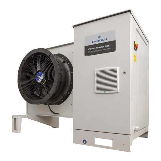
- Page 1 Application Guidelines Copeland Scroll ™ Refrigeration Units OME-16T OMTE-37T to OMTE-64T...
-
Page 2: Table Of Contents
About these guidelines..................... 1 Safety instructions ..................1 1.1 Icon explanation ....................1 1.2 Saf ety statements....................1 1.3 General instructions ................... 2 Product description..................3 2.1 General information about Copeland CO scroll ref rigeration unit ......3 2.2 EU Ecodesign Directive 2009/125/EC..............3 2.3 Main product features and dimensions.............. - Page 3 2.12.4 Alarms ....................22 2.13 XC Pro controller – Peripheral devices..............22 2.13.1 Variable frequency drive EVM ..............22 2.13.2 XEV20D Stepper valve actuator............... 23 2.13.3 Circuit breakers..................23 2.14 Compressor safety ..................23 2.14.1 Compressor motor protection ..............23 2.14.2 High-pressure safety (type-approved pressure limiter).........
- Page 4 5.2.2 To open the compressor chamber............40 5.2.3 To remove the fan safety grid ..............40 5.3 Replacing a compressor ................... 41 5.4 Gas cooler fins ....................41 5.5 Electrical connections ..................42 5.6 Routine leak testing ..................42 5.7 Gas cooler fan & motor ..................42 5.8 Pressure relief valves ..................
-
Page 6: About These Guidelines
Manuf acturer’s Declaration, available relevant standards please ref er www.climate.emerson.com/en-gb. These instructions should be retained throughout the lif etime of both the compressor and the ref rigeration unit. You are strongly advised to follow these safety instructions. Icon explanation WARNING... -
Page 7: General Instructions
General instructions WARNING Pressurized system! Serious personal injuries and/or system breakdown! Accidental system start before complete set-up must be avoided. Never leave the system unattended without locking it out electrically when it is on vacuum and has no ref rigerant charge, when it has a holding charge, or when the compressor service valves are closed. -
Page 8: Product Description
General information about Copeland CO scroll refrigeration unit Emerson has developed the Copeland CO scroll refrigeration unit to meet primarily the demands of the f ood retail and f ood service sectors. It is an air-cooled ref rigeration unit that uses the latest Copeland scroll transcritical compressors with inverter. -
Page 9: Main Product Features And Dimensions
Main product features and dimensions The ref rigeration units covered in these guidelines are released for CO (R744) ref rigerant only. They are available in four different sizes and are equipped with one or two gas cooler fans. The units are designed for medium temperature applications only. The inverter is calculated to drive the compressor in subcritical and transcritical applications. -
Page 10: Product Nameplate
scroll refrigeration unit (OME-16T) – Front view Figure 3: Dimensions of Copeland CO Product nameplate The ref rigeration unit nameplate shows model designation and serial number, as well as rated current and saf ety pressures. The compressor has its own nameplate with all electrical characteristics. Figure 4: Nameplate of Copeland CO scroll refrigeration units AGL_Unit_OMTE_CO... -
Page 11: Nomenclature
Nomenclature The model designation contains the f ollowing technical inf ormation about Copeland CO scroll ref rigeration units: Figure 5: Nomenclature of Copeland CO2 scroll refrigeration units Application range 2.6.1 Qualified refrigerant and oil Qualified refrigerant R744 (CO Qualified servicing oil PAG ZEROL RFL 68 EP Unit OME-16T-TFD... -
Page 12: Application Limits
Always operate the system with adequate superheat to avoid oil viscosity decrease. Additional measures in system design might help to avoid unacceptable lubrication conditions. For the application envelope, please refer to Select software at www.climate.emerson.com/en-gb. Recommendations for minimum suction superheat – lubrication conditions 2.6.3... -
Page 13: Bom Variations
Figure 7 shows the thermodynamic properties (p -h-diagram) of R744. Compared to other f luids traditionally used as refrigerants, its critical point at 31 °C is very low and its critical pressure at about 73.6 bar is high. Figure 7: Pressure/enthalpy diagram CO BOM variations The BOM (bill of material) number at the end of the unit designation indicates the different unit layouts and details. -
Page 14: P&I Diagrams
P&I diagrams 2.8.1 Single-compressor CO scroll refrigeration units Figure 8: P&I diagram of CO scroll refrigeration unit with single compressor Position Description Position Description Copeland CO scroll compressor High pressure limiter (variable speed) Copeland CO scroll compressor Compressor inverter (fixed speed) Oil separator Suction pressure Gas cooler... -
Page 15: Tandem-Compressor Co Scroll Refrigeration Units
2.8.2 Tandem-compressor CO scroll refrigeration units Figure 9: P&I diagram of CO scroll refrigeration units with two compressors Position Description Position Description Copeland CO scroll compressor High pressure limiter (variable speed) Copeland CO scroll compressor Compressor inverter (fixed speed) Oil separator Suction pressure Gas cooler Discharge pressure... -
Page 16: Main Components Description
Main components description Figure 10: Main components of CO scroll refrigeration unit (OME-16T) 2.9.1 Compressor The smallest unit contains one variable-speed compressor. All other units have two compressors. The f irst compressor is variable speed and the second one is f ixed speed. The compressors are installed in the compartment next to the electrical cabinet. -
Page 17: Electrical Cabinet
2.9.2 Electrical cabinet The electrical cabinet is located next to the the compressor compartment. All electrical components such as main unit controller, inverter, contactors, transformers, wiring terminals and f uses are installed in this area. The electrical cabinet is closed by a door. A f an is activated to control the temperature inside the cabinet. -
Page 18: High Pressure Valve (Hpv)
Technical data Supply frequency 230 for OME-16T / OMTE-37T Supply voltage 400 for OMTE-49T / OMTE-64T Min to max ambient -25 to +55 for OME-16T / OMTE-37T °C temperature -25 to +70 for OMTE-49T / OMTE-64T ErP 2015 IP class IP54 Fan motor type Fan blades... -
Page 19: Design Pressures
Figure 13: Design pressures of Copeland CO2 scroll refrigeration units NOTE: The design pressure PS is a safety-related value. The restrictions for reliable operation of the unit are defined by the application envelope which can be found in Select software at www.climate.emerson.com/en-gb. 2.9.9 Housing Copeland CO scroll ref rigeration units have a new, unique design. -
Page 20: Figure 15: Liquid Line And Suction Line
Figure 15: Liquid line and suction line Figure 16: Main switch and power supply cable gland AGL_Unit_OMTE_CO _EN_Rev01... -
Page 21: Co Scroll Refrigeration Unit Control - General
The XC Pro controller is a standard IPG315D Dixell controller. The controller is factory-set for -10 °C evaporating temperature. To achieve the required temperatures, Emerson recommends to change only the evaporating temperature as the rest of the parameters are already pre-set. -
Page 22: Figure 19: Visotouch Display - General Menu
Position Description Go to GENERAL MENU page Go to SCHEMATIC page Go to GAS COOLER page Go to SERVICE page Go to ALARM page Go to ALARM page Number of active alarms Go to COMPRESSORS page Number of running/available compressors Speed of variable speed compressor in % Go to GAS COOLER page Number of running/available fans... -
Page 23: How To Use The Xc Pro Controller
Figure 20: Visotouch display – Schematics Position Description Go to MAIN PAGE Go to PARAMETERS page Go to GAS COOLER page Go to MEDIUM TEMPERATURE SUCTION LINE page Table 12: Display description – Schematics 2.11 How to use the XC Pro controller 2.11.1 How to change parameters 1) In the GENERAL MENU go to the PARAMETERS page... -
Page 24: How To Switch The Xc Pro Controller On/Off
4) Select the group of parameters that need to be changed. In this example SetPoint " " 5) Navigate to the correct parameter using the arrows on the right. SETC1 is the setpoint of the " " evaporating temperature. Figure 23: SETPOINTS page 6) Click on now the value can be changed using the arrow buttons. -
Page 25: Xc Pro Controller - Functionality
2.12 XC Pro controller – Functionality The XC Pro controls the complete ref rigeration unit. It provides a lot of customization f eatures like alarms and special operating modes. Thanks to the high degree of flexibility, the user can either use the f actory-set alarms or set up their own alarms according to the application requirements. -
Page 26: Fan Speed / Gas Cooler Control
The lowest pumpdown setpoint will always be applied. The f ollowing diagram illustrates the controller logic: Ambient condition: Compressor setpoint: = 20 °C SETC1 = -10 °C SPF5 = 0 K SPF1 = 8 K Pumpdown setpoint based Pumpdown setpoint based on on ambient temperature: compressor setpoint: –... -
Page 27: Alarms
2.13.1 Variable frequency drive EVM The Emerson variable frequency drive EVM has been designed for applications that require flexible integration with systems via industrial Ethernet protocols and fieldbuses, together with advanced RFC-A open-loop motor control. Connection to RS485 networks using Modbus RTU allows for communication with the unit controller. -
Page 28: Xev20D Stepper Valve Actuator
Copeland CO scroll refrigeration units are equipped with scroll ZTW/ZTI compressors. The Emerson EVM variable frequency drive covers all relevant electrical protection features for the ZTW compressor. For more details see the EVM Inverter handbook. The ZTI compressor has an internal protection. -
Page 29: High-Pressure Safety (Type-Approved Pressure Limiter)
2.14.2 High-pressure safety (type-approved pressure limiter) A type-approved pressure limiter (according to EN 12263) with automatic reset is installed on the compressor. It is a normally-closed switch from Alco Controls. The pressure cut-out is set to 123 bar and the cut-in to 117 bar. Figure 31: High-pressure limiter 2.14.3 High-pressure safety control There are 3 pressure transmitters assembled in the unit. -
Page 30: Pressure Relief Valve - Liquid Receiver
2.14.5 Pressure relief valve – Liquid receiver There are two pressure relief valves (90 bar) on the liquid receiver, connected on a changeover valve. In case of ref rigerant blow-off, this allows f or easy replacement of the relief device without interruption of unit operation by using the second valve. -
Page 31: Oil Management Device - Om5 Traxoil
2.15 Oil management device – OM5 TraxOil™ The compressors in the Copeland CO scroll ref rigeration units are equipped with an Emerson OM5 TraxOil oil level management system. This device is intended to prevent the compressors from operating with insufficient oil by opening a valve which allows the oil to flow from the oil separator to the compressor. -
Page 32: Installation
Installation WARNING High pressure! Injury to skin and eyes possible! Be careful when opening connections on a pressurized item. Never install the unit at such a height that if the pressure relief valve opens, the gas flow can reach an individual’s head. IMPORTANT Always install the unit in such a way that all installation, commissioning and servicing works can be carried out safely and easily. -
Page 33: Lifting
3.1.3 Lifting The unit can be lif ted as described in Figure 38 below. Figure 38: Lifting points for CO2 scroll refrigeration units Refrigeration piping connections 3.2.1 Refrigeration piping installation and connections WARNING High pressure! Risk of personal injury! The units are pressurized with dry air. -
Page 34: Service Ports
Figure 39: Piping connections 3.2.2 Service ports There are 5 ports on single-compressor units and 6 ports on tandem-compressor units. Ports directly on the tube (marked in red in f igures below) must not be opened once the unit is under pressure. There is no Schraeder valve inserted. -
Page 35: Brazing Recommendations
4) Be sure tube f itting inner surface and tube outer surface are clean prior to assembly. 5) Both tubes are extended f rom the condensing unit housing, therefore Emerson recommends isolating the housing by using a wet cloth on the copper tubing. -
Page 36: Pressure Testing At Suction Side
Recommended brazing materials are listed in Table 17 below. Working Composition (% by weight) DIN EN Brazing alloy DVGW* number temperature ISO 17672 (°C) BrazeTec Ag145 DV-0150CM0043 25.5 4576 BrazeTec Ag134 DV-0150CM0045 27.5 3476 BrazeTec Ag244 DV-0150CM0044 4404 BrazeTec S 15 CuP284 BrazeTec S 5 CuP281... -
Page 37: Power Supply Connections
installer or the user of the equipment is responsible f or ensuring this and to consult with the electricity supplier as necessary. 3.3.1 Power supply connections WARNING Electrical cabinet door open! Danger of electric shock! Always make sure the electrical cabinet door is properly closed before starting the unit. The electrical connection of the ref rigeration unit to the power supply must be made by qualified technicians in compliance with the valid electrical standards, eg, DIN EN 60204-1. -
Page 38: Location & Fixings
Location & fixings IMPORTANT Dust and dirt contamination! Unit life reduction! The unit should always be installed in a location where clean airf low is ensured. External f ouling of the gas cooler f ins leads to high condensing temperatures or pressures and will reduce the lif etime of the unit. -
Page 39: Figure 47: Unit Mounted On Concrete Slab With Anti-Vibration Pads
Ideally, the unit should be mounted level on a solid concrete slab with anti-vibration pads between unit f eet and concrete as shown in Figure 47. Figure 47: Unit mounted on concrete slab with anti-vibration pads Select an installation location that meets the following conditions: 1) The location needs to be selected in such a way that nobody is disturbed by the airf low and the sound of the unit. -
Page 40: Start-Up & Operation
Start-up & operation WARNING High pressure! Risk of personal injury! Always keep sufficient distance f rom the pressure relief valve to avoid serious injury in the event of a sudden pressure release. WARNING Hot surfaces! Burning! Do not touch the compressor heads or discharge line as their surf aces can reach high temperatures both during operation and at standstill. -
Page 41: Charging Procedure
In order to prevent system overcharge f or high ambient temperatures Emerson recommends charging the liquid receiver only up to 60 % considering a typical piping length of 30 meters. Charging must be done with compressors switched on. -
Page 42: Oil Charging Procedure
After commissioning, the oil level should be checked and topped up if necessary. As mentioned in section 2.6.1 "Qualified refrigerant and oil", Emerson recommends charging with PAG ZEROL RFL 68 EP. -
Page 43: Maximum Compressor Cycle
The f actory settings of the system controller take into account the maximum number of permitted starts and stops of the compressor, as well as the running time and minimal downtime. Emerson recommends to change these settings only in exceptional cases, eg, when the liquid line pressure cannot be kept by the factory settings. -
Page 44: Maintenance & Repair
Hot surfaces! Burning! Do not touch the compressor heads or discharge line as their surf aces can reach high temperatures both during operation and at standstill. CAUTION Unauthorized parts! Unit damage! Only parts authorized by Emerson can be used for maintenance and replacement. 5.2.1 To open the electrical cabinet... -
Page 45: To Open The Compressor Chamber
5.2.2 To open the compressor chamber ▪ Unscrew the three screws located on the top of the compressor chamber cover and the green/yellow grounding cable, then lif t the cover. The compressor chamber can be opened on two sides. Figure 51: Opening the compressor chamber 5.2.3 To remove the fan safety grid WARNING... -
Page 46: Replacing A Compressor
As a general guide, it is advisable to do this at least once every two months. As a general rule and f or a clean environment Emerson recommends that the f ins be cleaned with liquid detergent diluted with clean water. The ref rigeration unit has a well-designed chassis and any cleaning solution should be able to drain away. -
Page 47: Electrical Connections
Electrical connections WARNING Isolating switch "On"! Electrical shock hazard! Turn of f the main power supply to de-energise the unit bef ore undertaking any task on electrical equipment. All condensing units will generate some degree of vibration. Copeland CO scroll refrigeration units are no exception. -
Page 48: Figure 53: Changeover Valve - Shaft In Open Position
Figure 53: Changeover valve – Shaft in open position Figure 54: Changeover valve – Shaft in closed position AGL_Unit_OMTE_CO _EN_Rev01... -
Page 49: Certification & Approval
Certification & approval ▪ Copeland CO scroll refrigeration units comply with the Low Voltage Directive LVD 2014/35/EU. The compliance is verified through harmonized standards: − EN 60335-1: Household and similar electrical appliances – Safety, General Requirements. − EN 60335-2-89: Household and similar electrical appliances – Safety, Particular requirements f or commercial refrigerating appliances with an incorporated or remote refrigerant condensing unit or compressor. -
Page 50: Appendix 1: Xc Pro Controller Alarm Menu
Appendix 1: XC Pro controller alarm menu Code Description Cause Action Reset Automatically if the number of activations is less than AL12 in the AL13 time when the input is disabled.The compressors restart working according to the working algorithm. Low-pressure switch Input 1 (the input is All compressors of Manually (if AL12 activations happened in the AL13 time) -
Page 51: Appendix 2: Temperature / Resistance Curve For Ntc
Appendix 2: Temperature / resistance curve for NTC Temp Resistance Temp Resistance Temp Resistance Temp Resistance Temp Resistance Temp Resistance (Ω) (Ω) (Ω) (Ω) (Ω) (Ω) (°C) (°C) (°C) (°C) (°C) (°C) 329500 67770 17960 5827 2228 973.1 -49.5 320200 -19.5 66170 10.5... - Page 52 Temp Resistance Temp Resistance Temp Resistance Temp Resistance Temp Resistance Temp Resistance (Ω) (Ω) (Ω) (Ω) (Ω) (Ω) (°C) (°C) (°C) (°C) (°C) (°C) -32.5 126550 -2.5 30390 27.5 9112.5 57.5 3266.5 87.5 1354.5 123300 29730 8944 3215 1336 -31.5 120200 -1.5 29105...
-
Page 53: Appendix 3: Temperature / Resistance Curve For Ptc
Appendix 3: Temperature / resistance curve for PTC Temp Resistance Temp Resistance Temp Resistance Temp Resistance Temp Resistance Temp Resistance Temp Resistance (Ω) (Ω) (Ω) (Ω) (Ω) (Ω) (Ω) (°C) (°C) (°C) (°C) (°C) (°C) (°C) 420.6 772.8 1240.5 1524.5 1841 -64.5 423.57... - Page 54 Temp Resistance Temp Resistance Temp Resistance Temp Resistance Temp Resistance Temp Resistance Temp Resistance (Ω) (Ω) (Ω) (Ω) (Ω) (Ω) (Ω) (°C) (°C) (°C) (°C) (°C) (°C) (°C) -47.5 522.35 -17.5 692.2 12.5 895.4 42.5 1132.05 72.5 1402.1 102.5 1705.75 132.5 2028 524.9...
-
Page 55: Appendix 4: Ecodesign Tables According To Regulation 2015/1095/Eu
Appendix 4: Ecodesign tables according to Regulation 2015/1095/EU DC in kW COP at this DC (measured or (measured or calculated) calculated) 14.32 1.43 12.73 1.97 10.45 2.77 8.51 4.03 Annual power consumption 29.851 SEPR 2.95 AGL_Unit_OMTE_CO _EN_Rev01... -
Page 56: Appendix 5: List Of Tables And Figures
Appendix 5: List of tables and figures Tables Table 1: Copeland CO scroll ref rigeration unit technical data ...........4 Table 2: Copeland CO scroll ref rigeration unit features ............4 Table 3: Qualified ref rigerant and oil ..................6 Table 4: BOM ........................8 Table 5: Legend of the P&I diagram of CO scroll ref rigeration units with single compressor ..9 Table 6: Legend of the P&I diagram of CO... -
Page 57: Disclaimer
3. Emerson does not assume responsibility for the selection, use or maintenance of any product. Responsibility for proper selection, use and maintenance of any Emerson product remains solely with the purchaser or end user. - Page 58 The Emerson logo is a trademark and service mark of Emerson Electric Co. Emerson Climate Technologies Inc. is a subsidiary of Emerson Electric Co. Copeland is a registered trademark and Copeland Scroll is a trademark of Emerson Climate Technologies Inc.. All other trademarks are property of their respective owners.