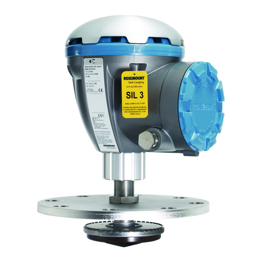
Emerson Rosemount 5900 Safety Manual For Use In Safety Instrumented Systems
Radar level gauge and tank hub
Hide thumbs
Also See for Rosemount 5900:
- Reference manual (100 pages) ,
- Instruction for installation, configuration, and operation (62 pages) ,
- Safety manual (46 pages)
Table of Contents
Quick Links
See also:
Reference Manual
Table of Contents

Related Manuals for Emerson Rosemount 5900


Summary of Contents for Emerson Rosemount 5900
- Page 1 Safety Manual 00809-0200-5100, Rev GB February 2017 ™ Rosemount 5900 Radar Level Gauge and 2410 Tank Hub Safety Manual for Use in Safety Instrumented Systems This manual is valid for model code Safety Certification (SIS) option 2 and 3 Certified to relevant requirements of IEC 61508:2010 parts 1-7...
- Page 3 For equipment service or support needs, contact your local Emerson Process Management/Rosemount Tank Gauging representative. Spare Parts Any substitution of non-recognized spare parts may jeopardize safety.
- Page 4 Safety Manual Title Page 00809-0200-5100, Rev GB February 2017 Title Page...
-
Page 5: Table Of Contents
Wiring diagram ..........12 4.1.2 The Rosemount 5900 terminal block .......14 4.1.3 Connecting the Rosemount 2410 to the 5900 . - Page 6 Safety Manual Contents 00809-0200-5100, Rev GB February 2017 5Section 5: Proof Test Check of surface measurement and verification of the relay function..52 5.1.1 Check of surface measurement ........52 5.1.2 Verification of the relay function .
- Page 7 Safety Manual Scope and Purpose of the Safety Manual 00809-0200-5100, Rev GB February 2017 Section 1 Scope and Purpose of the Safety Manual The purpose of the safety manual is to document all the information, relating to the Rosemount Tank Gauging system, which is required to enable integration into a safety-related system, in compliance with the requirements of IEC 61508.
- Page 8 Safety Manual Scope and Purpose of the Safety Manual 00809-0200-5100, Rev GB February 2017 Scope and Purpose of the Safety Manual...
- Page 9 Safety Manual Reference Documents 00809-0200-5100, Rev GB February 2017 Section 2 Reference Documents IEC 61508 IEC 61511 Rosemount Tank Gauging System Configuration Manual, Ref. no. 00809-0300-5100 Rosemount 2410 Tank Hub Reference Manual, Ref. no. 00809-0100-2410 Rosemount 5900S Radar Level Gauge Reference Manual, ...
- Page 10 Safety Manual Reference Documents 00809-0200-5100, Rev GB February 2017 Reference Documents...
-
Page 11: Purpose Of The Product
Rosemount 5900 The Rosemount 5900 is a radar level gauge developed for a wide range of applications at bulk liquid storage facilities. Different antennas can be used in order to meet the requirements of different applications. The 2-in-1 version of the Rosemount 5900 has two independent and galvanically isolated radar modules in the same transmitter enclosure using a single antenna. -
Page 12: Certification
System Data Sheet, Document No. 00813-0100-5100. If there are any echoes measured by the Rosemount 5900 which cannot be traced back to the product surface, note if there are any objects such as beams, heating coils etc. in the tank corresponding to the found echoes. - Page 13 Still-pipe Array Antenna with hinged hatch The Rosemount 5900 Radar Level Gauge including the SIL alarm output is not safety-rated during maintenance work. This includes opening of the 5900 still-pipe array antenna, hinged hatch version during for example manual gauging (hand-dip) or product sampling.
-
Page 14: Functional Specification Of The Safety Function
Safety Manual Scope of the Product 00809-0200-5100, Rev GB February 2017 3.2.2 Functional specification of the safety function The Rosemount Tank Gauging Safety System provides a SIL Alarm Relay output to indicate overfill or dry-run risk. No other output is related to the safety function. The Rosemount Tank Gauging Safety System provides the following safety functions: Measures the distance from the SIL Reference Point to the surface of a liquid in a tank ... -
Page 15: Maintenance
The devices in the Rosemount Tank Gauging Safety System may only be repaired or modified by authorized personnel trained by Emerson Process Management / Rosemount Tank Gauging. For upgrade of firmware, use the procedure in the Rosemount 5900S Radar Level Gauge Reference Manual (00809-0100-5900). - Page 16 Safety Manual Scope of the Product 00809-0200-5100, Rev GB February 2017 Scope of the Product...
-
Page 17: Installation And Commissioning
Rosemount Tank Gauging System Configuration Manual (Document No. 00809-0300-5100) Rosemount 5900 Instruction for Installation, Configuration, and Operation of Proof Test Function with Reference Reflector (Document No. 00809-0200-5900) When the devices are up and running proceed with the Safety Alarm configuration as described “Safety alarm setup”... -
Page 18: Wiring Diagram
Safety Manual Installation and Configuration 00809-0200-5100, Rev GB February 2017 4.1.1 Wiring diagram Figure 4-1. Wiring diagram for Rosemount 2410 and Rosemount 5900 with SIL option Rosemount 2410 Tank Hub Rosemount 5900 Radar Level Gauge Non-Intrinsically Safe Intrinsically Safe (Exi) - Page 19 Safety Manual Installation and Configuration 00809-0200-5100, Rev GB February 2017 Table 4-1. Installation drawings for the Rosemount 5900 and 2410 Safety Instrumented System Drawing Issue Title D9240041-963 Electrical Installation Drawing 5900 Series 1-in-1 (1oo1D) SIL 2 D9240041-964 Electrical Installation Drawing 5900 Series 2-in-1...
-
Page 20: The Rosemount 5900 Terminal Block
X3: Primary Tankbus out Optional jumpers between X3 and X4 for connection to second level gauge when using the 2-in-1 version of the Rosemount 5900 for SIL 3 X4: Secondary Tankbus in installations. No jumpers are used for SIL 2. -
Page 21: Connecting The Rosemount 2410 To The 5900
IS I/O+ IS Input/Output + IS I/O - IS Input/Output - Alarm - SIL Alarm - (connect to terminal block on Rosemount 5900) Alarm + SIL Alarm + (connect to terminal block on Rosemount 5900) GND_1 GND_1 Housing chassis/Tankbus shield... -
Page 22: Rosemount 2410 Relay Output Connection
Safety Manual Installation and Configuration 00809-0200-5100, Rev GB February 2017 4.1.4 Rosemount 2410 relay output connection The Rosemount 2410 SIL relay output is connected to the Exd/Exe terminal block as illustrated below. Figure 4-4. 2410 non-IS terminal block Ground screw Ground screws Non-IS (Exd/Exe) compartment SIL Alarm Relay Output... - Page 23 Figure 4-6 on page 18. These illustrations show two configuration examples for a SIL 3 and a SIL 2 system, respectively. Figure 4-5. SIL Alarm relay output for a 5900 (2-in-1) complying with SIL 3 Rosemount 5900 (2-in-1) Rosemount 2410 SIL Alarm Relay...
- Page 24 Safety Manual Installation and Configuration 00809-0200-5100, Rev GB February 2017 Figure 4-6. SIL Alarm relay output for a 5900 (1-in-1) complying with SIL 2 Rosemount 5900 (2-in-1) Rosemount 2410 Rosemount 2410 SIL Alarm Relay Tankbus SIL Alarm Relay output to...
-
Page 25: Safety Alarm Setup
Safety alarm setup The Safety Alarm Setup procedure is used to set up the SIL Alarm Limits, the tank geometry, and to adjust the Rosemount 5900 Level Gauge for optimum measurement performance in the tank. Prior to starting the Safety Alarm Setup, ensure that the actual distance to the product surface is known. -
Page 26: Safety Alarm Parameters And Tank Geometry
Installation and Configuration 00809-0200-5100, Rev GB February 2017 4.2.2 Safety alarm parameters and tank geometry illustrate the tank geometry for a Rosemount 5900 with Parabolic Figure 4-7 Figure 4-8 Antenna and Array Antenna in a Rosemount Tank Gauging Safety System. Figure 4-9 show the geometry with an optional Proof Test Reference Reflector. - Page 27 Safety Manual Installation and Configuration 00809-0200-5100, Rev GB February 2017 Figure 4-8. Tank Geometry for Safety Alarm configuration of a Rosemount 5900 with LPG/LNG antenna SIL Used Hold Off Distance SIL Reference Point SIL Antenna Hold Off Distance SIL LPG Pin...
- Page 28 Safety Manual Installation and Configuration 00809-0200-5100, Rev GB February 2017 Figure 4-9. Tank Geometry for a Rosemount 5900 with Parabolic antenna and Proof Test Reference Reflector SIL Reference Point SIL Reference Reflector Proof Test Distance Reference Reflector SIL High Alarm Limit...
- Page 29 Safety Manual Installation and Configuration 00809-0200-5100, Rev GB February 2017 Figure 4-10. Tank Geometry for a Rosemount 5900 with Array Antenna and Proof Test Reference Reflector SIL Reference Point SIL Reference Reflector Distance SIL High Alarm Limit Proof Test Reference Reflector...
-
Page 30: Amplitude Thresholds
Safety Manual Installation and Configuration 00809-0200-5100, Rev GB February 2017 4.2.3 Amplitude thresholds Figure 4-11. Amplitude thresholds are used to filter out disturbing echoes and noise Measuring Range Distance From SIL Reference Point 1. SIL Used Hold Off Distance 2. SIL Near Zone Distance 3. - Page 31 Safety Manual Installation and Configuration 00809-0200-5100, Rev GB February 2017 Figure 4-12. The Amplitude Threshold is used to filter out noise and radar echoes from disturbing objects in the tank Amplitude SIL Reference Point Disturbing object SIL Hold Off Distance Adjustment SIL High Alarm Limit SIL Surface Distance...
- Page 32 Safety Manual Installation and Configuration 00809-0200-5100, Rev GB February 2017 Figure 4-13. Amplitude Threshold in tank with 5900 Radar Level Gauge and Reference Reflector Amplitude SIL Reference Point Disturbing object SIL Hold Off Distance Adjustment Reference Reflector SIL High Alarm Limit Reference Reflector Product surface SIL Surface Distance...
-
Page 33: Setting The Sil High Alarm Limit
Safety Manual Installation and Configuration 00809-0200-5100, Rev GB February 2017 4.2.4 Setting the SIL High Alarm Limit The desired SIL High Alarm Limit needs to be adjusted for the expected product level rate. “Margin to add” in Table 4-8 is a safety margin to add to the desired SIL High Alarm Limit. This ensures that the reaction time of the 5900 for different level rates is taken into account when specifying the desired SIL High Alarm Limit. - Page 34 Safety Manual Installation and Configuration 00809-0200-5100, Rev GB February 2017 Example Table 4-10. Example of how to configure the SIL High Alarm Limit Antenna Parabolic Desired SIL High Alarm Limit (as measured from the SIL Reference 2500 mm Point) Maximum Level Rate that may occur in the tank 1.5 mm/s Margin to add (Level Rate<2 mm/s) 120 mm...
-
Page 35: Setting The Sil Low Alarm Limit
Safety Manual Installation and Configuration 00809-0200-5100, Rev GB February 2017 4.2.5 Setting the SIL Low Alarm Limit The desired SIL Low Alarm Limit needs to be adjusted for the expected product level rate. “Margin to subtract” in Table 4-11 is a safety margin to subtract from the desired SIL Low Alarm Limit. -
Page 36: Safety Alarm Configuration
Low Alarm Limit The SIL 3 Rosemount Tank Gauging Safety System includes a 2-in-1 Rosemount 5900 with two independent radar level gauges using the same antenna and tank opening. The Safety Alarm has to be separately configured for each of the two gauges as described in “Safety alarm... - Page 37 Safety Manual Installation and Configuration 00809-0200-5100, Rev GB February 2017 A brief overview of the setup procedure for the Rosemount Tank Gauging Safety System is illustrated in Figure 4-14 Figure 4-14. Setup procedure for the Rosemount Tank Gauging Safety System STEP 1 DEVICE VERIFICATION Verify that correct equipment is installed and configured...
- Page 38 Start the TankMaster WinSetup configuration program. Ensure that you are logged on to TankMaster as Administrator. In the WinSetup workspace, click the right mouse button on the icon for the Rosemount 5900 Radar Level Gauge: Properties Choose the Properties option. The 5900 RLG Properties window appears.
- Page 39 Safety Manual Installation and Configuration 00809-0200-5100, Rev GB February 2017 Safety Alarm Click the Safety Alarm button to open the Safety Alarm window. Installation and Configuration...
- Page 40 Safety Manual Installation and Configuration 00809-0200-5100, Rev GB February 2017 Step 1 Device verification In the Device Information pane check that the Device Id is identical to the Device Id on the main label attached to the 5900 housing. For a 5900 2-in-1 version, the Device Id is divided in two parts.
- Page 41 Safety Manual Installation and Configuration 00809-0200-5100, Rev GB February 2017 Step 2 Calibration of surface To configure the Safety Alarm parameters of the 5900 gauge, click the Change Parameters button to open the Change Safety Alarm Parameters window. In the Change Safety Alarm Parameters window, configure the Safety Alarm Parameters as described in Table 4-13 on page 36 (see also...
- Page 42 Safety Manual Installation and Configuration 00809-0200-5100, Rev GB February 2017 Table 4-13. Safety Alarm Parameters Safety Alarm Description Parameter SIL High Alarm Limit Set the desired SIL High Alarm Limit; see “Setting the SIL High Alarm Limit” on page The SIL High Alarm Limit can be disabled, see Appendix E: Disabling the SIL High Alarm further information.
- Page 43 Set according to the requirements imposed by the safety PLC. (1) Contact Emerson Process Management / Rosemount Tank Gauging in case you need information on how to use this function. In the Change Safety Alarm Parameters window click the Apply button.
- Page 44 Safety Manual Installation and Configuration 00809-0200-5100, Rev GB February 2017 Once the 5900 has detected the product surface, you may need to make minor adjustments of the SIL Calibration Distance in order to accurately match the SIL Surface Distance (measured by the 5900) with the actual distance to the product surface. A positive SIL Calibration Distance will decrease the SIL Surface Distance.
- Page 45 Safety Manual Installation and Configuration 00809-0200-5100, Rev GB February 2017 Step 3 Final adjustment of amplitude thresholds Check if there is any Margin Echo between the SIL Reference Point and the product surface, i.e. if the SIL Margin Echo Distance is less than the SIL Surface Distance. If this is the case, you will need to adjust the amplitude thresholds in order to optimize signal/noise ratio.
- Page 46 Safety Manual Installation and Configuration 00809-0200-5100, Rev GB February 2017 Step 4 Verify safety alarm parameters In the Safety Alarm window click the Change Safety Mode button to open the Change Safety Alarm Mode window: Verify that identical Safety Alarm Parameter values appear in the Value and Read Back columns.
- Page 47 Safety Manual Installation and Configuration 00809-0200-5100, Rev GB February 2017 Perform a final verification of the following parameters: Check that SIL High Alarm Limits are within approved limits, see “Setting the SIL High Alarm Limit” on page If SIL Low Alarm Limit is enabled: check that SIL Low Alarm Limits are within approved ...
- Page 48 Safety Manual Installation and Configuration 00809-0200-5100, Rev GB February 2017 Click the Print Screen button to print a copy of the current Safety Alarm window. The printed copy can be used at a future occasion to check that no changes have been done to the SIL Rosemount Tank Gauging Safety System since last time it was configured.
-
Page 49: How To Filter Out Lpg Verification Pin Or Reference Reflector
Safety Manual Installation and Configuration 00809-0200-5100, Rev GB February 2017 4.2.7 How to filter out LPG Verification Pin or Reference Reflector In LPG tanks, a verification pin is mounted in the still-pipe in order to allow verification of level measurements in a pressurized tank. At a certain stage of the Safety Alarm Setup you should temporarily filter out the verification pin in order to let the 5900 detect the product surface. -
Page 50: How To Adjust The Sil Amplitude Threshold
Safety Manual Installation and Configuration 00809-0200-5100, Rev GB February 2017 4.2.8 How to adjust the SIL Amplitude Threshold If the SIL Surface Distance deviates significantly from the distance to the actual product surface, the gauge may have locked on a disturbing object. Then you will have to filter out the disturbing echo by adjusting the SIL Amplitude Threshold as described below. -
Page 51: Changing The Current Alarm Configuration
Start the TankMaster WinSetup configuration program. Ensure that you are logged on as Administrator. In the WinSetup workspace, click the right mouse button on the Rosemount 5900 Radar Level Gauge icon. Choose the Properties option. The RLG Properties window appears. - Page 52 Safety Manual Installation and Configuration 00809-0200-5100, Rev GB February 2017 Change Safety Mode Click the Change Safety Mode button to open the Change Safety Alarm Mode window. Installation and Configuration...
- Page 53 Safety Manual Installation and Configuration 00809-0200-5100, Rev GB February 2017 Device Id Password Change to Not Approved In the Change Safety Alarm Mode window enter the Device Id and the SIL Password. The default password=”1234”. The password can be changed once the Safety Mode is set to “Not Approved”. Click the Change to Not Approved button.
-
Page 54: 10How To Adjust The Sil Hold Off Distance
Safety Manual Installation and Configuration 00809-0200-5100, Rev GB February 2017 4.2.10 How to adjust the SIL Hold Off Distance In case the presented SIL Surface Distance indicates that the product surface is close to the nozzle, adjust the SIL Hold Off Distance instead of the SIL Amplitude Threshold. It is recommended that this method is used only if the disturbing echo is located more than 1 meter above the SIL High Alarm Limit. -
Page 55: 11How To Enable Sil Low Alarm Limit
Safety Manual Installation and Configuration 00809-0200-5100, Rev GB February 2017 4.2.11 How to enable SIL Low Alarm Limit To enable the SIL Low Alarm Limit function: In the Safety Alarm window, click the Change Parameters button to open the Change Safety Alarm Parameters window. -
Page 56: 12How To Disable Sil Low Alarm Limit
Safety Manual Installation and Configuration 00809-0200-5100, Rev GB February 2017 4.2.12 How to disable SIL Low Alarm Limit To disable the SIL Low Alarm Limit function: In the Safety Alarm window, click the Change Parameters button to open the Change Safety Alarm Parameters window. - Page 57 “Verification of the relay function” on page Note The Rosemount 5900 gauge is not safety-rated during maintenance work, configuration changes, or other activity that affects the Safety Function. Alternative means should be used to ensure process safety during such activities.
-
Page 58: Check Of Surface Measurement And Verification Of The Relay Function
Safety Manual Proof Test 00809-0200-5100, Rev GB February 2017 Check of surface measurement and verification of the relay function By combining the two tests Check of Surface Measurement and Verification of the Relay Function approximately 93% of the DU (dangerous undetected) failures will be detected. 5.1.1 Check of surface measurement This proof test will detect approximately 69% of the DU (dangerous undetected) failures not... -
Page 59: Verification Of The Relay Function
Safety Manual Proof Test 00809-0200-5100, Rev GB February 2017 5.1.2 Verification of the relay function This proof test verifies the Safety Relay function itself, i.e. whether the Safety Relay is able to open and close. The test will detect approximately 26% of the DU (dangerous undetected) failures not detected by the diagnostics in the Rosemount Tank Gauging Safety System. -
Page 60: System Test
Safety Manual Proof Test 00809-0200-5100, Rev GB February 2017 System test This proof test will detect approximately 99% of the DU (dangerous undetected) failures not detected by the diagnostics in the Rosemount Tank Gauging Safety System. The test includes testing the relay response when the product surface reaches the relay set point. The overfill and dry-run protection function should be checked by filling and emptying the tank in order to test the system response when the product surface reaches the relay set points. -
Page 61: Sil High Alarm Test
February 2017 SIL High Alarm test The SIL High Alarm Test is based on using the Rosemount 5900 gauge to measure the distance from the SIL Reference Point to a reference reflector placed above the current SIL High Alarm (see... - Page 62 Safety Manual Proof Test 00809-0200-5100, Rev GB February 2017 Verify that the SIL Reference Reflector/LPG Pin Distance and SIL Reference Reflector/LPG Pin Amplitude parameters are displayed. In case no Reference Reflector is installed, these parameters will be equal to zero and the Test SIL High Alarm button will be disabled. Click the Test SIL High Alarm button.
- Page 63 Safety Manual Proof Test 00809-0200-5100, Rev GB February 2017 In the Test SIL High Alarm window, verify the current test time, or change the test time to the desired value. Enter your signature. Click the Start Test button to start the test procedure. The SIL High Alarm Test Data window with updated parameters will appear.
- Page 64 Safety Manual Proof Test 00809-0200-5100, Rev GB February 2017 When the proof test is finished, you will be asked to fill in a form in order to create a SIL Safety Alarm Test report. Fill in the proof test form and click the Save button to store the form. A report in PDF format will automatically be created.
- Page 65 Safety Manual Proof Test 00809-0200-5100, Rev GB February 2017 The following parameters will be presented in the report and the SIL High Alarm Test Results window: Table 5-1. Safety parameters Safety Parameter Description Safety Status “Alarm” during the SIL High Alarm test. Once the test is finished successfully, Safety Status will return to “OK”.
-
Page 66: Viewing A Sil High Alarm Test Report
Safety Manual Proof Test 00809-0200-5100, Rev GB February 2017 5.3.1 Viewing a SIL High Alarm Test report Reports in Adobe Acrobat pdf format are available via the Proof Test History window. To view a report: Open the Proof Test window. In the SIL Safety Alarm pane, click the History button. - Page 67 Safety Manual Proof Test 00809-0200-5100, Rev GB February 2017 In the SIL Alarm Test History window, choose the desired test report from the drop-down menu, or by using the Back and Forward buttons. Choose the desired test report Show Test Report Click the Show Test Report button to view the selected report.
- Page 68 Safety Manual Proof Test 00809-0200-5100, Rev GB February 2017 The report includes device information and device status. There is also information regarding the result of the proof test, for example whether alarms did sound or if emergency shutdown was activated. Figure 5-1.
- Page 69 Safety Manual Terms and Definitions 00809-0200-5100, Rev GB February 2017 Section 6 Terms and Definitions BPCS Basic Process Control System Demand rate How often it will be required from a safety integrity system (or the safety function) to react on inputs from process to bring it into a safe state, i.e.
- Page 70 Safety Manual Terms and Definitions 00809-0200-5100, Rev GB February 2017 Terms and Definitions...
-
Page 71: 5900 And 2410 (Sil 2, 1-In-1)
5900 and 2410 (SIL 2, 1-in-1) Failure rates for a Rosemount Tank Gauging Safety System consisting of a Rosemount 5900 Radar Level Gauge and a Rosemount 2410 Tank Hub (1oo1D) according to IEC 61508. Table A-1. Failure rates according to IEC 61508... -
Page 72: 5900 And 2410 (Sil 2, 2-In-1)
Safety Manual Parameters Related to the Safety Function 00809-0200-5100, Rev GA February 2017 5900 and 2410 (SIL 2, 2-in-1) Table A-3. Failure rates according to IEC 61508 Failure Category Failure Rates (in FIT) Fail Safe ( 1117 Fail Dangerous Detected ( Fail Dangerous Undetected (... -
Page 73: Assumptions
Safety Manual Parameters Related to the Safety Function 00809-0200-5100, Rev GA February 2017 Assumptions Failure rates are constant, wear out mechanisms are not included Propagation of failures is not relevant The device is installed per manufacturer’s instructions Failures during parameterization are not considered ... - Page 74 Safety Manual Parameters Related to the Safety Function 00809-0200-5100, Rev GA February 2017 Parameters Related to the Safety Function...
- Page 75 Safety Manual Supported Antennas 00809-0200-5100, Rev GA February 2017 Appendix B Supported Antennas Table B-1 lists the antenna types and antenna sizes which are supported for the Rosemount Tank Gauging Safety System. Table B-1. Supported antennas and antenna sizes. Antenna Antenna Type Antenna Size Antenna Size...
- Page 76 Safety Manual Supported Antennas 00809-0200-5100, Rev GA February 2017 Supported Antennas...
-
Page 77: Cappendix C: Safety System Identification
SIL High Alarm Test 6.C0 Device Id The Device Id of a Rosemount 5900 gauge with 2-in-1 option consists of two parts: “xxx-yyy”, where “xxx” is the Device Id of the primary device and “yyy” is the Device Id of the secondary device. -
Page 78: Baselines
Safety Manual Safety System Identification 00809-0200-5100, Rev GB February 2017 Baselines Ensure that the SIL Baselines for the 5900 Radar Level Gauge and the 2410 Tank Hub are identical when a new Rosemount Tank Gauging Safety System is installed. Figure C-1. 5900 main label Model code Serial no. -
Page 79: Sil Level
Figure C-3. 5900 terminal block with SIL label SIL 2/ SI L 3 label The Rosemount 5900 has different terminal blocks for the SIL 2 and SIL 3 options. The SIL 3 option includes two separate level gauges which need to be configured individually as described “Safety alarm setup”... - Page 80 Safety Manual Safety System Identification 00809-0200-5100, Rev GB February 2017 Safety System Identification...
-
Page 81: Dappendix D: Sil Measurement Status
SIL Measurement Status Safety Manual February 2017 00809-0200-5100, Rev GB Appendix D SIL Measurement Status In the Safety Alarm and other windows the current measurement status is presented in the Measurement Status field. In case of an error, it displays a status code in hexadecimal format according to Table D-1. - Page 82 Several messages can be combined. If, for example, the two messages Amplitude peak detected in alarm area and PM Device Error appear simultaneously the result would be: 0x00000001 Hex + 0x04000000 Hex = 0x04000001 Hex. Contact Emerson Process Management/Rosemount Tank Gauging service department to report failures. SIL Measurement Status...
-
Page 83: Eappendix E: Disabling The Sil High Alarm
Safety Manual Disabling the SIL High Alarm 00809-0200-5100, Rev GB February 2017 Appendix E Disabling the SIL High Alarm Ensure that appropriate measures are taken to prevent overfill in case the SIL High Alarm is disabled. The Disable SIL High Alarm function may be useful in dry-run applications when only SIL Low Alarm Limit is needed. - Page 84 Safety Manual Disabling the SIL High Alarm 00809-0200-5100, Rev GB February 2017 To disable the SIL High Alarm Limit function: Ensure that the safety system is unlocked, i.e. in the Not Approved state (see “Changing the current alarm configuration” on page 45 for information).
- Page 85 Safety Manual Cone Pipe Antenna 00809-0200-5100, Rev GB February 2017 Appendix F Cone Pipe Antenna Table F-1 provides recommended settings of Calibration Distance and Pipe Diameter for Cone Pipe Antennas. Due to minor imperfections of the actual pipes, these figures may need to be slightly adjusted in order to minimize deviations between actual and measured SIL Surface Distance.
- Page 86 Safety Manual Cone Pipe Antenna 00809-0200-5100, Rev GB February 2017 Cone Pipe Antenna...
- Page 87 Safety Manual Dry-run Configuration 00809-0200-5100, Rev GB February 2017 Appendix G Dry-run Configuration This section describes the recommended procedure to configure the SIL Safety System for Dry-run applications. Prior to setting up the SIL Safety System for Dry-run it Amplitude has to be installed and configured as normal.
- Page 88 Safety Manual Dry-run Configuration 00809-0200-5100, Rev GB February 2017 4. Specify and configure the SIL Low Alarm Limit. Amplitude 1. SIL Low Alarm Limit 2. Echo from product surface 5. Disable the SIL High Alarm Limit: 3. 2. SIL Used Hold Off Distance SIL High Alarm Limit= Disabled (Type 0).
- Page 89 Safety Manual Dry-run Configuration 00809-0200-5100, Rev GB February 2017 12. Set SIL Amplitude Threshold = 1400 mV. Verify that 1. SIL Near Zone Distance this value is less than 25% of the SIL Surface 2. SIL Used Hold Off Distance Amplitude and three times the SIL Margin Echo 3.
- Page 90 Safety Manual Dry-run Configuration 00809-0200-5100, Rev GB February 2017 Dry-run Configuration...
- Page 92 Dubai, United Arab Emirates www.emerson.com/en-us/Terms-of-Use. +971 4 8118100 The Emerson logo is a trademark and service mark of Emerson Electric Co. Rosemount and Rosemount logotype are trademarks of Emerson. +971 4 8865465 All other marks are the property of their respective owners.