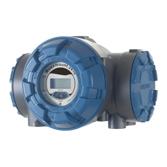
Emerson Rosemount 2410 Reference Manual
Tank hub
Hide thumbs
Also See for Rosemount 2410:
- Reference manual (192 pages) ,
- Instruction manual (34 pages) ,
- Instructions manual (30 pages)
Table of Contents
Table of Contents

Related Manuals for Emerson Rosemount 2410


Summary of Contents for Emerson Rosemount 2410
- Page 1 Reference Manual 00809-0100-2410, Rev DA March 2017 ™ Rosemount 2410 Tank Hub...
- Page 3 Read this manual before working with the product. For personal and system safety, and for optimum product performance, make sure you thoroughly understand the contents before installing, using, or maintaining this product. ™ For equipment service or support needs, contact your local Emerson Automation Solutions/Rosemount Tank Gauging representative. Spare Parts Any substitution of non-recognized spare parts may jeopardize safety.
- Page 4 Title Page Reference Manual 00809-0100-2410, Rev DA March 2017 Title Page...
-
Page 5: Table Of Contents
Reference Manual Contents 00809-0100-2410, Rev DA March 2017 Contents 1Section 1: Introduction 1.1 Safety messages..............1 1.2 Symbols . - Page 6 4.4 Basic configuration of a Rosemount 2410 Tank Hub ....... .
- Page 7 Reference Manual Contents 00809-0100-2410, Rev DA March 2017 6Section 6: Service and Troubleshooting 6.1 Safety messages..............77 6.2 Service .
- Page 8 Contents Reference Manual 00809-0100-2410, Rev DA March 2017 A.3 Electrical specifications............111 A.3.1 Power supply (nominal values) .
- Page 9 Reference Manual Contents 00809-0100-2410, Rev DA March 2017 BAppendix B: Product Certifications B.1 European Directive Information ........... 119 B.2 Ordinary Location Certification .
- Page 10 Contents Reference Manual 00809-0100-2410, Rev DA March 2017 viii Contents...
-
Page 11: Safety Messages
Reference Manual Introduction 00809-0100-2410, Rev DA March 2017 Section 1 Introduction Safety messages ..............page 1 Symbols . -
Page 12: Symbols
Reference Manual Introduction 00809-0100-2410, Rev DA March 2017 Symbols The CE marking symbolizes the conformity of the product with the applicable European Community Directives. The EU-Type Examination Certificate is a statement of a Notified Certification Body declaring that this product meets the Essential Health and Safety Requirements of the ATEX directive The FM APPROVED Mark indicates that the equipment is... -
Page 13: Manual Overview
Section 3: Installation covers installation considerations as well as mechanical and electrical installation. Section 4: Configuration describes how to configure the Rosemount 2410 Tank Hub by using the TankMaster WinSetup configuration program. Section 5: Operation describes the integral display and how to specify display variables. It also includes start-up information, error messages, and LED functionality. -
Page 14: Technical Documentation
Product data sheets Rosemount Tank Gauging System Data Sheet (00813-0100-5100) Rosemount 2460 System Hub Product Data Sheet (00813-0100-2460) Rosemount 2410 Product Data Sheet (00813-0100-2410) Rosemount 5900S Product Data Sheet (00813-0100-5900) Rosemount 5900C Product Data Sheet (00813-0100-5901) ... -
Page 15: Service Support
Service support For service support contact the nearest Emerson Automation Solutions/Rosemount Tank Gauging represen- tative. Contact information can be found on the web site site emerson.com/rosemount tank gauging. Product recycling/disposal Recycling of equipment and packaging should be taken into consideration and disposed of in accordance with local and national legislation/regulations. - Page 16 Reference Manual Introduction 00809-0100-2410, Rev DA March 2017 Introduction...
-
Page 17: Introduction
“Tankbus” on page 29). The Rosemount 2410 is designed for use in hazardous area Zone 1 (Class 1, Division 1) and communicates with field devices in Zone 1 via the intrinsically safe Tankbus. The Rosemount 2410 is available in two versions for single tanks or multiple tanks. The multiple tanks version supports up to 10 tanks and 16 devices. - Page 18 At start-up, communication settings and optional hardware configuration is presented as well as whether it is a Single tank or Multiple tank version of the Rosemount 2410 Tank Hub. Using the input from a Rosemount 5900S Radar Level Gauge and one or two pressure sensors, the Rosemount 2410 can be configured for online presentation of Observed Density to a host computer.
-
Page 19: Communication
Both the Primary bus and the Secondary bus can be used for either TRL2 Modbus (standard) or RS485 Modbus communication On the Secondary bus you may use other communication protocols as well, such as Enraf, Varec etc. Figure 2-2. Typical configuration of a Rosemount 2410 and 2460 System Hub connected to PC/Host Field devices Tankbus... - Page 20 Overview Reference Manual 00809-0100-2410, Rev DA March 2017 Figure 2-4. Typical configuration of a Rosemount 2410 with wireless connection to Smart Wireless Gateway and PC/Host Field devices Secondary bus (IS): Smart Wireless Wireless HART THUM Adapter Tankbus TankMaster Primary bus:...
-
Page 21: Components
Reference Manual Overview 00809-0100-2410, Rev DA March 2017 Components Figure 2-5. Rosemount 2410 components A. Intrinsically safe terminal compartment B. Non-intrinsically safe terminal compartment C. Integral display (optional) D. Write protection switch E. Cable entries for IS connection (two ½ - 14 NPT) F. -
Page 22: System Overview
Reference Manual Overview 00809-0100-2410, Rev DA March 2017 System overview The Rosemount Tank Gauging system is a state-of-the art inventory and custody transfer radar tank level gauging system. It is developed for a wide range of applications at refineries, tank farms and fuel depots, and fulfills the highest requirements on performance and safety. - Page 23 Rosemount 5900S Temperature Transmitter NON-HAZARDOUS AREA HAZARDOUS AREA Radar Level Gauge Rosemount TankMaster PC Rosemount 2230 Display Rosemount 2410 Tank Hub Rosemount 3051S Pressure Transmitter Tankbus Rosemount 2460 System Hub Rosemount 5900S Rosemount 2180 Radar Level Gauge Field Bus Modem...
- Page 24 Rosemount 5900S Radar Level Gauge Temperature Transmitter Emerson Wireless 775 THUM Adapter Rosemount TankMaster PC Rosemount 2230 Display Rosemount 2410 Tank Hub Rosemount 3051S Pressure Transmitter Emerson Wireless 1420 Gateway Tankbus Rosemount 5900S Emerson Wireless Radar Level Gauge 775 THUM Adapter...
- Page 25 Reference Manual Overview 00809-0100-2410, Rev DA March 2017 Figure 2-8. Rosemount Tank Gauging system architecture in a Foundation fieldbus network Rosemount 2240S Rosemount 5900S Radar Level Gauge Temperature Transmitter NON-HAZARDOUS AREA HAZARDOUS AREA Rosemount 2230 Display Rosemount 3051S Pressure Transmitter FOUNDATION Fieldbus Rosemount 5900S Power Supply...
- Page 26 Rosemount 2410 Tank Hub The Rosemount 2410 Tank Hub acts as a power supply to the connected field devices in the hazardous area using the intrinsically safe Tankbus. The tank hub collects measurement data and status information from field devices on a tank. It has two external buses for communication with various host systems.
- Page 27 Reference Manual Overview 00809-0100-2410, Rev DA March 2017 Rosemount 5900S Radar Level Gauge The Rosemount 5900S Radar Level Gauge is an intelligent instrument for measuring the product level inside a tank. Different antennas can be used in order to meet the requirements of different applications. The Rosemount 5900S can measure the level of almost any product, including bitumen, crude oil, refined products, aggressive chemicals, LPG and LNG.
- Page 28 An Emerson Wireless THUM Adapter allows wireless communication between a Rosemount 2410 Tank Hub and an Emerson Wireless Gateway. The gateway is the network manager that provides an interface between field devices and the TankMaster inventory software or host / DCS systems.
-
Page 29: Installation Procedure
March 2017 Installation procedure Follow these steps for a proper installation: Review Mounting Considerations. “Installation considerations” on page Mount the Rosemount 2410. Tank Hub “Mechanical installation” on page Wire the Rosemount 2410. “Electrical installation” on page Make sure covers and cable/conduit connections are tight. - Page 30 Reference Manual Overview 00809-0100-2410, Rev DA March 2017 Overview...
-
Page 31: Safety Messages
High voltage that may be present on leads could cause electrical shock: Avoid contact with leads and terminals. Make sure the main power to the Rosemount 2410 Tank Hub is off and the lines to any other external power source are disconnected or not powered while wiring the gauge. -
Page 32: Installation Considerations
The Rosemount 2410 Tank Hub can also be mounted on the tank roof if this is the preferred location. In case the tank hub is exposed to long periods of sunshine, a sunshade should be used to prevent it from being heated to temperatures above the maximum operating temperature. -
Page 33: Mechanical Installation
Installation 00809-0100-2410, Rev DA March 2017 Mechanical installation The Rosemount 2410 is designed for mounting on a pipe stand or on a wall. Note Ensure that the Rosemount 2410 is installed to minimize vibration and mechanical shock. 3.3.1 Pipe mounting 1. -
Page 34: Wall Mounting
Reference Manual Installation 00809-0100-2410, Rev DA March 2017 3.3.2 Wall mounting 1. Mount the bracket on the wall by using four M8 screws and flat washers. 70 mm Note! Countersunk screws are not suitable. Ø 9 mm 94 mm 2. Attach the tank hub to the bracket and tighten the screw. -
Page 35: Electrical Installation
3.4.2 Power supply The Rosemount 2410 Tank Hub accepts supply voltage 48 - 240 Vac (50/60 Hz) and 24 - 48 Vdc. The Rosemount 2410 provides intrinsically safe power to all devices connected to the Tankbus (see “Tankbus” on page 29). -
Page 36: Cable Selection For Power Supply
Reference Manual Installation 00809-0100-2410, Rev DA March 2017 3.4.3 Cable selection for power supply Cables must be suitable for the supply voltage and approved for use in hazardous areas, where applicable. For instance, in the U.S., explosion-proof conduits must be used in the vicinity of the vessel. Suitable conduits with sealing device or flame proof cable glands must be used depending on local requirements. -
Page 37: Cable Selection For The Tankbus
3.4.5 Cable selection for the Tankbus Use shielded twisted pair wiring for the Rosemount 2410 Series in order to comply with FISCO requirements and EMC regulations. The preferred cable is referred to as type “A” fieldbus cable. The cables must be suitable for the supply voltage and approved for use in hazardous areas, where applicable. -
Page 38: Power Budget
Rosemount 2051 Pressure Transmitter 18 mA The Rosemount 2410 Tank Hub is available in a single tank version as well as a multiple tank version which supports up to 10 tanks May be fewer than the 16 devices per segment, stated in the F ™... -
Page 39: Tankbus
In many cases distances are relatively short between the Rosemount 2410 and field devices on the tank and you may use existing cables as long as the FISCO requirements are fulfilled (see “Cable selection for the Tankbus”... - Page 40 In this case the current consumption would be 128 mA allowing a cable length of 677 m (2221 ft) between the Rosemount 2410 Tank Hub and the field devices on the tank. With fewer devices on the Tankbus, an even longer cable would be allowed.
- Page 41 The example illustrated in Figure 3-2 includes a tank located 300 m away from a Rosemount 2410 Tank Hub acting as power supply. In the calculations below it is assumed that the cable length between the field devices on the tank can be ignored.
- Page 42 3-3, includes two tanks with a Rosemount 2410 Tank Hub acting as power supply to the field devices on both tanks. The first tank is located 300 m away from the Rosemount 2410 Tank Hub and the second tank a further 350 m away.
- Page 43 Sufficient equipotential bonding of the installation must be ensured. The device is connected via the bolt on the housing to the system’s potentializer. Figure 3-4. Dimensions (mm) 173.5 185.5 Part no. 6853511-493. Contact Emerson Automation Solutions/Rosemount Tank Gauging for more information. Installation...
- Page 44 Reference Manual Installation 00809-0100-2410, Rev DA March 2017 Figure 3-5. Segment coupler features A. Switch for capacitive or direct connection between shield and housing potential B.Switch for activating terminating resistor C. Current limitation for all ports via a rotary switch; 30, 35, 45, or 60 mA D.Connection of housing potential E.
- Page 45 Figure 3-6. Example of a Rosemount Tank Gauging system with field devices connected to the Tankbus via segment couplers Rosemount 5400 Level Transmitter Rosemount 644 Temperature Transmitter Segment coupler with active Rosemount 2230 Display terminator (end of trunk) Rosemount 2240S Temperature Transmitter (Spur<60 m) (Spur<60 m) Rosemount 2410 Tank Hub Segment coupler Tankbus (trunk) Installation...
-
Page 46: Typical Installations
Terminators are installed at both ends of the fieldbus segment as required in a F fieldbus OUNDATION system. In this example the terminators are enabled in the Rosemount 2410 Tank Hub and a field device (Rosemount 2240S) at the end of the network segment. In addition to the field instruments on the Tankbus,... - Page 47 Reference Manual Installation 00809-0100-2410, Rev DA March 2017 Non I.S. current loop alternative options: 1. Passive current loop. Input voltage range: 10.5 - 35 V 2. Active current loop. Output voltage range: 12.8 - 24 V @ 21.75 - 0 mA. I.S.
- Page 48 4-wire cable for connection of Primary Tankbus and Secondary Rosemount 5900S Tankbus Radar Level Gauge Primary Rosemount 2410 Primary Tank Hub is Secondary Rosemount 2410 connected to the electronic unit of the Secondary Tank Hub is 5900S 2-in-1 level gauge...
- Page 49 Figure 3-9. Example of a Rosemount Tank Gauging system with a Rosemount 2410 Tank Hub connected to several field devices at the end of the Tankbus (fieldbus segment)
- Page 50 If a field device is connected to the end of the Tankbus (fieldbus segment), the built-in terminator can be used. Another option is to use a separate bus terminator. Figure 3-10. Example of a Rosemount Tank Gauging system with several tanks daisy-chained to a Rosemount 2410 Tankbus length up to 1000 meter depending on...
- Page 51 Segment coupler Segment coupler Segment coupler The Rosemount 2410 Tank Hub has a built-in terminator and intrinsically safe power supply with integrated power conditioner. Note that the total length of the Tankbus (fieldbus segment) must be within the FISCO specifications and the spurs must not exceed 60 meter, see “Cable selection for the Tankbus”...
- Page 52 Rosemount 2410 Tank Hub with intrinsically safe power supply, integrated power conditioner, and built-in terminator External terminator Rosemount 2230 Display Rosemount 644 Temperature Transmitter Red+ Black- ½ inch NPT Part no. 6853511-494. Contact Emerson Automation Solutions/Rosemount Tank Gauging for more information. Installation...
-
Page 53: Cabling For The Trl2/Rs485 Bus
00809-0100-2410, Rev DA March 2017 3.4.9 Cabling for the TRL2/RS485 Bus A standard Rosemount Tank Gauging system includes one or several Rosemount 2410 Tank Hubs communicating with a Rosemount 2460 System Hub using the TRL2/RS485 Modbus protocol as shown Section 2: Overview. - Page 54 Reference Manual Installation 00809-0100-2410, Rev DA March 2017 RS485 Bus The RS485 bus should meet the following requirements: twisted and shielded pair wiring characteristic impedance of 120 maximum cable length 1200 m / 4000 ft. Installation...
-
Page 55: 10Non-Is Connection
Reference Manual Installation 00809-0100-2410, Rev DA March 2017 3.4.10 Non-IS connection The non-IS explosion-proof/flameproof compartment has a terminal block for connecting power supply, ® communication buses to host systems, relay outputs, and HART 4-20 mA analog input and output. 1. Ensure that the power supply is switched off. 2. - Page 56 Reference Manual Installation 00809-0100-2410, Rev DA March 2017 Figure 3-14. Non-IS terminal compartment A. Non-IS compartment B. Wiring with drip loop C. Ground screws D. Cable entries E. Terminal block F. Cover jam screw Installation...
- Page 57 00809-0100-2410, Rev DA March 2017 Conductor recommendations Ensure that you use cables suitable for the terminal block of the Rosemount 2410. The terminal block is designed for cables that meet the specifications as illustrated below. Figure 3-15. Conductor and insulation requirements...
- Page 58 Reference Manual Installation 00809-0100-2410, Rev DA March 2017 Use a screw driver to insert the conductor into the terminal block as illustrated in Figure 3-16. Figure 3-16. Use a screw driver to connect the conductor to the terminal block Terminal block Conductor Installation...
-
Page 59: 11Non-Is Terminal Block
Reference Manual Installation 00809-0100-2410, Rev DA March 2017 3.4.11 Non-IS terminal block Figure 3-17. Terminal block in the explosion-proof/flameproof compartment XP/Exd/Exe Ground screws for communication bus Ground screw shields Table 3-8. Terminal assignment for non-intrinsically safe side (XP/Exd/Exe) Terminal Designation Function N / - Power, Neutral / DC -... - Page 60 Power supply The Rosemount 2410 accepts supply voltage 24-48 Vdc and 48-240 Vac (50/60 Hz). Primary communication bus The Rosemount 2410 communicates with a host or a 2460 System Hub via TRL2 Modbus or RS-485 Modbus protocol. Secondary communication bus The secondary bus can be used for communication using a number of protocols such as TRL2 Modbus, HART 4-20 mA, Enraf, Varec and L&J.
- Page 61 March 2017 Non-IS terminal block for SIL safety systems For Safety Integrity Level (SIL) systems the Rosemount 2410 has a terminal block on the Non-IS side with connection to a SIL Alarm Relay output. Figure 3-18. Non-IS (XP/Exd/Exe) terminal block...
-
Page 62: 12Is Connection
Reference Manual Installation 00809-0100-2410, Rev DA March 2017 3.4.12 IS connection The IS compartment has a terminal block for connecting the intrinsically safe Tankbus for communication with field devices on the tank. This terminal block is also used for intrinsically safe HART 4-20 mA analog input/output communication. -
Page 63: 13Intrinsically Safe Terminal Block
Housing chassis/Tankbus shield Tankbus The devices on the tank communicates with the Rosemount 2410 via the intrinsically safe Tankbus. All field devices in the Rosemount Tank Gauging system have built-in communication modems for FISCO fieldbus (FF) communication and will automatically communicate with the Rosemount 2410 OUNDATION when connected to the Tankbus. - Page 64 IS terminal block for SIL safety systems For Safety Integrity Level (SIL) systems the Rosemount 2410 has a terminal block with a SIL Alarm output for connection to a Rosemount 5900S Radar Level Gauge. Figure 3-21. IS/Exi terminal block for SIL systems...
-
Page 65: 14Wiring Diagrams
March 2017 3.4.14 Wiring diagrams Figure 3-22. Wiring diagram on the intrinsically safe (IS/Exi) side Terminal block on intrinsically safe side IS/Exi ROSEMOUNT 2410 Not used (future option) SIL systems: Alarm IS secondary bus Intrinsically safe Tankbus Rosemount 2230 Rosemount 2240S... - Page 66 Reference Manual Installation 00809-0100-2410, Rev DA March 2017 Figure 3-23. Wiring diagram on the non-intrinsically safe (XP/Exd/Exe) side Terminal block on Non-intrinsically safe side XP/Exd/Exe ROSEMOUNT 2410 ROSEMOUNT 2410 Power supply Secondary bus Secondary power Relay outputs Primary bus Modem...
- Page 67 Reference Manual Installation 00809-0100-2410, Rev DA March 2017 Figure 3-24. Wiring diagram for Rosemount 2410 and Rosemount 5900S in a SIL safety system Installation...
- Page 68 Reference Manual Installation 00809-0100-2410, Rev DA March 2017 Installation...
-
Page 69: Safety Messages
Basic configuration of a Rosemount 2410 Tank Hub ....... . . -
Page 70: Introduction
See the Rosemount Tank Gauging System Configuration Manual (Document no. 00809-0300-5100) for more information on how to use the TankMaster WinSetup software to configure the Rosemount 2410 Tank Hub. See also the Rosemount Wireless TankGauging System reference manual (Document no. -
Page 71: Basic Configuration Of A Rosemount 2410 Tank Hub
Depending on the particular system configuration, a Rosemount 2410 Tank Hub may communicate directly with a host computer or via a Rosemount 2460 System Hub. In case the Rosemount 2410 is connected to a Rosemount 2460 System Hub, you will have to specify which communication protocol channel to be used. -
Page 72: Advanced Configuration
Appendix C: Advanced Configuration Configuration using TankMaster WinSetup A Rosemount 2410 Tank Hub can easily be installed and configured by using the TankMaster Winsetup configuration program. The WinSetup installation wizard guides you through the basic configuration needed for starting up a Rosemount 2410. -
Page 73: Installation Wizard
March 2017 4.6.1 Installation wizard The TankMaster WinSetup wizard is the recommended tool for installing the Rosemount 2410 and supports basic configuration. To configure a Rosemount 2410 do the following: 1. Start the installation wizard in TankMaster WinSetup. Install New... -
Page 74: Installing A Rosemount 2460 System Hub
8. Verify that Host ports and Field ports are properly configured. Host ports are used for communication with TankMaster work stations or other host systems. Field ports are used for communication with field devices such as the Rosemount 2410 Tank Hub, the Rosemount 5900S Radar Level Gauge, and others. -
Page 75: Safety Messages
Reference Manual Operation 00809-0100-2410, Rev DA March 2017 Section 5 Operation Safety messages ..............page 65 Integral display . -
Page 76: Integral Display
68 for more information on start-up information. When the Rosemount 2410 is up and running the display presents Level, Signal Amplitude, Volume and other measurement variables depending on how the display is configured. The available parameters are listed in Table 5-1 on page The display has two rows for data presentation. - Page 77 Reference Manual Operation 00809-0100-2410, Rev DA March 2017 Table 5-1. Measurement variables and presentation on the Rosemount 2410 display Presentation on Variable Description display Level LEVEL Product level Distance from the upper reference point to the product Ullage ULLAGE surface...
-
Page 78: Start-Up Information
March 2017 Start-up information When the Rosemount 2410 starts up, all LCD segments light up for approximately 5 seconds. The start-up information appears on the display when the software initialization procedure is finished. The Primary Bus configuration appears first, followed by the Secondary Bus configuration. Each item appears a few seconds on the display: Table 5-2. -
Page 79: Error Messages
In case of an error, the upper row shows “ERROR” and the lower row toggles between “FAIL” and the error code. Figure 5-2. Error codes can be presented on the Rosemount 2410 display A. “ERROR” indication B. Fail/Error code The following error codes are used: Table 5-3. -
Page 80: Led
Operation Reference Manual 00809-0100-2410, Rev DA March 2017 There are three Light Emitting Diodes (LED) on the Rosemount 2410 front for status and error information. Figure 5-3. The Rosemount 2410 has three LEDs A. Error LED (Red) B. Status LED (Yellow) C. -
Page 81: Led Start-Up Information
00809-0100-2410, Rev DA March 2017 5.5.1 LED Start-Up information When the Rosemount 2410 is starting, both the Status and the Error LEDs indicate possible hardware or software errors as shown in Table 5-5 below: Table 5-5. LEDs are used for error indication at Rosemount 2410 start-up... -
Page 82: Error Led
Operation Reference Manual 00809-0100-2410, Rev DA March 2017 5.5.2 Error LED In normal operation the Error LED (Red) is turned off. In case a device error occurs, the LED will flash a sequence that corresponds to the error code followed by a five second pause. Figure 5-4. - Page 83 Reference Manual Operation 00809-0100-2410, Rev DA March 2017 Example In case of a device error, the red LED will repeat a flash sequence that corresponds to the particular type of error that occurred. For example, in case of a Display error (code=6), the LED will show a sequence of 6 flashes followed by a 5 seconds pause.
-
Page 84: Specifying Display Variables
The display will alternate between the selected items at a rate given by the Display Toggle Time parameter. When the Rosemount 2410 is installed and configured, the display can easily be set up with the Rosemount TankMaster WinSetup program to show tanks and measurement variables. The current display settings can be changed at any time in the Rosemount 2410 Local Display window as shown below: 1. - Page 85 March 2017 7. Click the OK button to save the configuration and close the window. 8. In the Rosemount 2410 Tank Hub window click the OK button to save the configuration and close the window. See the Rosemount Tank Gauging System Configuration Manual (Document no. 00809-0300-5100) for more information on using the TankMaster Winsetup PC software to configure the Rosemount 2410 Tank Hub.
-
Page 86: Rev Da March
Reference Manual Operation 00809-0100-2410, Rev DA March 2017 Operation... -
Page 87: Safety Messages
Reference Manual Service and Troubleshooting 00809-0100-2410, Rev DA March 2017 Section 6 Service and Troubleshooting Safety messages ..............page 77 Service . -
Page 88: Service
To view input or holding registers: 1. Start the TankMaster WinSetup program. 2. In the TankMaster WinSetup workspace window, click the right mouse button on the Rosemount 2410 Tank Hub device icon. 3. Choose the View Input Registers or View Holding Registers option, or from the Service menu choose Devices>View Input Registers / View Holding Registers. -
Page 89: Editing Holding Registers
Reference Manual Service and Troubleshooting 00809-0100-2410, Rev DA March 2017 Predefined 4. Choose Predefined for a basic selection of registers. Choose the All option if you would like to view a range of registers by your own choice. For the All option, specify a range of registers by setting a start value in the Start Register input field, and the total number of registers to be displayed in the Number of Registers field (1-500). -
Page 90: Device Live List
6.2.3 Device Live List The Rosemount 2410 Tank Hub Device Live List lets you view devices connected to the Tankbus. You can, for example, see Device Id, Tag, and whether the devices are configured or not. The Device Live List is useful when you are going to configure devices in a Rosemount Tank Gauging system, in order to verify that the required devices are connected to the Tankbus. - Page 91 March 2017 Item Description “Yes” indicates that the device is configured in the Rosemount 2410 tank Configured database, i.e. the device is mapped to a particular tank. Bit 1 of the Live List Status input register which indicates the current Tankbus Opened communication status of the device.
-
Page 92: Configuration Backup
Input and holding registers can be stored on disk, which can be useful for backup purposes and trouble- shooting. You can save a predefined set of Holding registers to make a backup copy of the current Rosemount 2410 Tank Hub configuration. To save the current configuration to file do the following: 1. -
Page 93: Configuration Recovery
This can be useful, for example, if you would like to recover configuration data. To load a backup database do the following: 1. In the TankMaster WinSetup workspace select the Rosemount 2410 Tank Hub icon that represents the device for which you want to load a new database. -
Page 94: Diagnostics
6.2.6 Diagnostics TankMaster WinSetup offers the option to view diagnostic registers for the Rosemount 2410 Tank Hub. The diagnostic registers are selected from available input and holding registers to provide a quick overview of the current device status. For a more comprehensive troubleshooting you may use the View Input Registers function (see also section “Viewing Input and Holding registers”... -
Page 95: Device Firmware Upgrade
March 2017 6.2.7 Device firmware upgrade The Rosemount TankMaster WinSetup program allows you to upgrade the Rosemount 2410 Tank Hub and other devices in a Rosemount Tank Gauging system with new firmware. Note In case the current firmware version is significantly older than the new one, it is recommended that you load the default configuration database once the device is reprogrammed. - Page 96 9. Click the Start Programming button to activate device programming. 10.Programming may take up to two hours for a Rosemount 2410 connected to a TankMaster PC via a 2460 System Hub. The programming procedure will continue with one device after the other until all Tank Hubs selected in the Program Devices window are upgraded.
-
Page 97: Write Protection
3. Click the right mouse button on the device icon that represents the Rosemount 2410: Write Protect 4. Choose the Write Protect option to open the Rosemount 2410 Tank Hub Write Protect window: 5. Choose Protected in the New State drop-down list. -
Page 98: Write Protection Switch
6.2.9 Write protection switch A switch on the front of the Rosemount 2410 Tank Hub can be used to prevent unauthorized changes of the holding register database. Figure 6-2. The Rosemount 2410 Tank Hub write protection switch on the built-in integral display... -
Page 99: 10Simulation Mode
Rosemount Tank Gauging System Configuration Manual (Document No. 00809-0300-5100). 1. In the TankMaster WinSetup workspace select the Rosemount 2410 icon. 2. Click the right mouse button and choose the Simulation option to open the Rosemount 2410 Tank Hub Simulation window: 3. - Page 100 00809-0100-2410, Rev DA March 2017 6. Click the Start button to start simulating the tank parameters. 7. In the WinSetup workspace the Rosemount 2410 icon changes to the following appearance to indicate that Simulation Mode is active: Simulation mode active Note Simulation continues for the specified period of time.
-
Page 101: 11Testing The Relays
6.2.11 Testing the relays The Manual Control of Relay function lets you manually open or close the Rosemount 2410 Tank Hub built-in relays in order to verify the relay function. After the specified Safety Reset Time the relay automatically returns to normal mode. -
Page 102: 12Relay Output Configuration
Service and Troubleshooting Reference Manual 00809-0100-2410, Rev DA March 2017 6.2.12 Relay output configuration To change the Normally Open/Normally Closed settings of the K1 and K2 relays, do the following: 1. Disconnect the power supply. 2. Disconnect the relays. Front cover 3. -
Page 103: 13Loading The Default Database
Note The communication address of the device remains unaltered when the default database is loaded. Note When the default database is loaded to the Rosemount 2410 Tank Hub, measurement units are reset to Metric units. To load the default database: 1. -
Page 104: 14Logging Measurement Data
6.2.14 Logging measurement data The Rosemount 2410 supports logging of diagnostic registers. This function is useful for verifying that the gauge works properly. The logging function can be accessed by using the TankMaster WinSetup program. To start logging do the following: 1. -
Page 105: Troubleshooting
Check wire insulation for possible short circuits to Wiring ground. Check that the Rosemount 2410 Tank Hub is connected to the right communication port on the control room PC (if no 2460 System Hub or FCU 2160 is used). - Page 106 Reference Manual 00809-0100-2410, Rev DA March 2017 Symptom Possible cause Action Check the Rosemount 2410 Tank Hub; check the Error LED or the integral display for information. Check the 2460 System Hub (or 2160 Field Communication Unit). Check the Field Bus Modem.
- Page 107 Too many devices on the Tankbus Remove one or more devices from the Tankbus. The Rosemount 2410 Tank Hub supports a single tank. The multiple tank version of the Rosemount 2410 supports up to 10 tanks. Service and Troubleshooting...
- Page 108 No communication with one or more devices on Check Device Status input register, see “Device the Tankbus status” on page 102. Software or hardware failure Contact Emerson Automation Solutions/Rosemount Tank Gauging service department. Service and Troubleshooting...
- Page 109 Solutions/Rosemount Tank Gauging service department. Check the model code to find out what type of Rosemount 2410 Tank Hub that is used: Single tank Too many devices connected to the or Multiple tank version. Tankbus Change to a Rosemount 2410 Tank Hub for ...
- Page 110 Configuration Manual (Document No. 00809-0300-5100) for more information on how to configure ATD devices such as a Rosemount 2240S Multi-Input Temperature Transmitter. If default database is loaded to the Rosemount 2410 Tank Hub, do one of the following: Incorrect temperature reading from in TankMaster WinSetup verify system units and ...
- Page 111 “Loading the default database” on register setup page 93 and restart the Rosemount 2410 Tank Hub. Reset holding registers to the default database Corrupt holding registers setting, see “Loading the default database” on page 93 and restart the Rosemount 2410 Tank Hub.
-
Page 112: Device Status
Service and Troubleshooting Reference Manual 00809-0100-2410, Rev DA March 2017 6.3.1 Device status The current device status is shown in Input Register 1000. You can view the device status register by opening the Diagnostic window (see “Diagnostics” on page 84) or the View Input Registers window (see “Viewing Input and Holding registers”... -
Page 113: Warning Messages
Input register no. 6228. Aux warning Bit 0: Internal temperature Bit 1: Power FF stack warning Input register no. 6232. Contact Emerson Automation Input register no. 6236. Solutions/Rosemount Tank Gauging Bit 0: Device restarted service department. Bit 1: Device open failed... - Page 114 Configuration tab. Map conflict device 1 TV no. TV number 0 - 1019 (Level, Ullage, (TV=Tank Variable) Level Rate, Signal Strength etc.) Contact Emerson Automation Solutions/Rosemount Tank Gauging Map conflict device 2 Input register no. 6268 service department. Input register no. 6270 Map conflict device 2 TV no.
-
Page 115: Error Messages
March 2017 6.3.3 Error messages Error messages may be displayed on the Rosemount 2410 integral display and in the Rosemount Tankmaster program. You also have the option to view Input Register 1002 for an overview of active device errors (see “Diagnostics”... - Page 116 Bit 0: Internal temperature out of limits Bit 1: Internal temp measurement failed Aux Error Bit 2: Internal temperature device Contact Emerson Automation failed Solutions/Rosemount Tank Gauging Bit 3: Relay 1 service department Bit 4: Relay 2 Bit 5: Power FF Stack Error Input register no.
-
Page 117: Aappendix A: Specifications And Reference Data
OUNDATION A.1.2 Multiple tank version A.2.2 Field bus For a Rosemount 5300/5400/5900 system configuration: Primary field bus: Rosemount 2410 communicates with a host or The software supports 16 field devices and 10 tanks per hub ® a field communication unit via TRL2 Modbus , RS485 Modbus, ®... -
Page 118: Analog Inputs/Outputs
Specifications and Reference Data Reference Manual March 2017 00809-0100-2410, Rev DA A.2.4 Analog inputs/outputs The hub supports analog output and input 4-20 mA/HART, active or passive, IS or non-IS. The analog output is available as certified SIL 2. Table A-1. Field bus combination matrix (Non-SIL) Primary Field Bus options Analog out Analog In... - Page 119 Reference Manual Specifications and Reference Data March 2017 00809-0100-2410, Rev DA Table A-2. Field bus combination matrix (SIL) Primary Field Bus options Analog In Analog out TRL2 RS485 Enraf passive passive (non-IS) (non-IS) Code R TRL2 SIL 2 (relay) SIL 2 (relay) Enraf SIL 2 (relay) SIL 2 (relay)
-
Page 120: Analog Input/Output
Specifications and Reference Data Reference Manual March 2017 00809-0100-2410, Rev DA A.2.5 Analog input/output Ambient temperature Free water level Analog input Vapor pressure Maximum number of input channels: 1 Liquid pressure Input Current range: 0-23 mA Air pressure ... -
Page 121: Electrical Specifications
Specifications and Reference Data Reference Manual March 2017 00809-0100-2410, Rev DA A.3 Electrical specifications Table A-4. Power budget A.3.1 Power supply (nominal values) Field device Power consumption 24-48 VDC (-15% to +10%) 5900S or 5900C Radar Level Gauge 50 mA 48-240 VAC (-15% to +10%), 50/60 Hz 5900S Radar Level Gauge, 2-in-1 100 mA... -
Page 122: Power And Relay Cabling
Depends on cable. For details see the Rosemount Tank Gauging System Data Sheet (document number 00813-0100-5100) A.3.6 Built-in Tankbus terminator The Rosemount 2410 Tank Hub has a built-in tank bus terminator which can be disconnected if required) Specifications and Reference Data... -
Page 123: Mechanical Specifications
Specifications and Reference Data Reference Manual March 2017 00809-0100-2410, Rev DA A.4 Mechanical specifications A.5 Environmental specification A.4.1 Housing material A.5.1 Ambient temperature Polyurethane-covered die-cast aluminum -40 to 70 °C (-40 to 158 °F). Minimum start-up temperature is -50 °C (-58 °F). A.4.2 Cable entry (connection/glands) With LCD display: -25 to 70 °C (-13 to 158 °F) Non-IS side: Two ½... -
Page 124: Dimensional Drawings
Specifications and Reference Data Reference Manual March 2017 00809-0100-2410, Rev DA A.6 Dimensional drawings Figure A-2. Rosemount 2410 Tank Hub dimensions 254 mm 164 mm 193 mm Specifications and Reference Data... -
Page 125: Ordering Information
Specifications and Reference Data Reference Manual March 2017 00809-0100-2410, Rev DA A.7 Ordering Information Model Product Description 2410 Tank Hub Tankbus: Number of Tanks Single tank Multiple tanks (Maximum 5 Rosemount 5300/5400 transmitters can be connected to one Tank Hub) Tankbus: Power and Communication ™... - Page 126 Specifications and Reference Data Reference Manual March 2017 00809-0100-2410, Rev DA Safety Certification (SIS) Certified IEC 61508 SIL 3 (using relay 1xSPST, solid state. Certification valid only when connected to a safety-certified (7)(8) Rosemount 5900 according to reference manual) Certified IEC 61508 SIL 2 (using analog or relay output) (8)(9) None, ready for upgrade of safety certification (SIS) None...
- Page 127 Specifications and Reference Data Reference Manual March 2017 00809-0100-2410, Rev DA (11) Custody Transfer Type Approval OIML R85 E 2008 performance certification CMI (Czech Republic W&M approval) NMI (Australia) PTB (German W&M approval) TJA (Estonia W&M approval) GUM (Poland) Ministero (Italy) GOST (Kazakhstan) LNE (France) BMS (Belgium W&M)
- Page 128 Specifications and Reference Data Reference Manual March 2017 00809-0100-2410, Rev DA Options - none or multiple selections are possible (13) IEC 61508 certificate and FMEDA data (14) TÜV/DIBt WHG Approval for Overfill protection (14) SVTI Approval for overfill protection (Switzerland) Engraved SST tag plate 3-year limited warranty 5-year limited warranty...
-
Page 129: European Directive Information
B.3 Installing Equipment in North America The most recent revision of the EU Declaration of Conformity can be found at Emerson.com/Rosemount. The US National Electrical Code (NEC) and the Canadian Electrical Code (CEC) permit the use of Division marked equipment in Zones B.2 Ordinary Location Certification... -
Page 130: North America
Product Certifications Reference Manual March 2017 00809-0100-2410, Rev DA B.4 North America Markings: AIS/I/1/CD XP-AIS/I/1/CD/T4 Ta = -50°C to +70°C USA Explosion-proof DIP/II,III/1/EFG/T4 Ta = -50°C to +70°C; Certificate: FM16US0123X Standards: FM Class 3600 – 2011, I/1/Ex d e [ib] IIB T4 Ta = -50°C to +70°C FM Class 3610 –... - Page 131 Reference Manual Product Certifications March 2017 00809-0100-2410, Rev DA Canada Explosion-proof Markings: AIS/I/1/CD Certificate: FM16CA0068X XP-AIS/I/1/CD/T4 Ta = -50°C to +70°C Standards: CSA C22.2 No 0.4 – 2004 (2009), DIP/II,III/1/EFG/T4 Ta = -50°C to +70°C; CSA C22.2 No. 0.5 - 1982 (2008), I/1/AEx d e [ib] IIB T4 Ta = -50°C to +70°C CSA C22.2 No.
-
Page 132: Europe
Product Certifications Reference Manual March 2017 00809-0100-2410, Rev DA B.5 Europe Markings: II 2(2) G Ex d e [ib] IIB T4 Ta = -50°C to 70°C; IP66, IP67 ATEX Flame-proof II 2(1) G Ex d e [ia IIC] IIB T4 Certificate: FM10ATEX0012X Standards: EN 60079-0:2009, Ta = -50°C to 70°C;... -
Page 133: International
Reference Manual Product Certifications March 2017 00809-0100-2410, Rev DA B.6 International Markings: Ex d e [ib] IIB T4 Gb Ex d e [ia IIC Ga] IIB T4 Gb IECEx Flame-proof Ex d e ib IIB T4 Gb Certificate: IECEx FMG 10.0005X Standards: IEC 60079-0:2007-10, IEC 60079-1:2007-04, IEC 60079-7:2006-07,... -
Page 134: Brazil
Product Certifications Reference Manual March 2017 00809-0100-2410, Rev DA B.7 Brazil INMETRO Flame-proof Markings: Ex de [ib] IIB T4 Gb Certificate: IEx 11.0074 Ex de [ia IIC Ga] IIB T4 Gb Standards: ABNT NBR IEC 60079-0:2008, Ex de ib IIB T4 Gb ABNT NBR IEC 60079-1:2009, Tamb= -50 °C to +70 °C ABNT NBR IEC 60079-7:2008,... -
Page 135: Japan
Reference Manual Product Certifications March 2017 00809-0100-2410, Rev DA B.9 Japan Markings: Ex d [ib] IIB T4 Ex ib[ib] IIB T4 Japan Flame-proof -20°C Ta +60°C Certificate: TC20552 Ex marking Comm. Bus Group μ μ Ex d [ib] IIB T4 FISCO 14.96 343.3... -
Page 136: B.12Conduit Plugs And Adapters
Standards: EN60079-0:2012, See the “Manuals & Drawings” CD ROM that is shipped with the EN60079-1:2007, IEC60079-7:2007 Rosemount 2410 Tank Hub for electronic copies of the system control drawings. Markings: II 2 G Ex de IIC Gb Drawings are also available on: B.12.1 Conduit Plug Thread Sizes... - Page 137 Reference Manual Product Certifications March 2017 00809-0100-2410, Rev DA Figure B-1. System control drawing Product Certifications...
- Page 138 Product Certifications Reference Manual March 2017 00809-0100-2410, Rev DA Product Certifications...
- Page 139 Reference Manual Product Certifications March 2017 00809-0100-2410, Rev DA Product Certifications...
- Page 140 Product Certifications Reference Manual March 2017 00809-0100-2410, Rev DA Product Certifications...
- Page 141 Reference Manual Product Certifications March 2017 00809-0100-2410, Rev DA Product Certifications...
- Page 142 Product Certifications Reference Manual March 2017 00809-0100-2410, Rev DA Product Certifications...
- Page 143 Reference Manual Product Certifications March 2017 00809-0100-2410, Rev DA Product Certifications...
- Page 144 Product Certifications Reference Manual March 2017 00809-0100-2410, Rev DA Product Certifications...
-
Page 145: Safety Messages
Reference Manual Advanced Configuration March 2017 00809-0100-2410, Rev DA Appendix C Advanced Configuration Safety messages ..............page 135 Advanced configuration in Winsetup . - Page 146 Advanced Configuration Reference Manual March 2017 00809-0100-2410, Rev DA High voltage that may be present on leads could cause electrical shock: Avoid contact with leads and terminals. Make sure the mains power to the Radar Transmitter is off and the lines to any other external power source are disconnected or not powered while wiring the transmitter.
-
Page 147: Advanced Configuration In Winsetup
WinSetup configuration software. To access the advanced configuration options for the Rosemount 2410, do the following: 1. In the TankMaster WinSetup workspace, click the right mouse button on the Rosemount 2410 Tank Hub icon. 2. Choose the Properties option. The 2410 Tank Hub window appears. -
Page 148: Primary Bus
00809-0100-2410, Rev DA Primary bus The Rosemount 2410 has a Primary Bus which is used for communication with a Rosemount 2460 System Hub. It may also be connected directly to a control room PC. The Primary Bus supports TRL2, RS485, and other communication buses. The Rosemount 2410 automatically detects what modem is installed in the Primary Bus slot and communication parameters are set accordingly. -
Page 149: Secondary Bus
TRL2 Modbus, Enraf, Varec, and L&J. To open the Secondary Bus window: 1. In the WinSetup workspace click the right mouse button on the Rosemount 2410 icon. 2. Choose the Properties option. -
Page 150: Relay Output
00809-0100-2410, Rev DA Relay output The Rosemount 2410 has two relays which can be configured with one or two set points. Virtual relay output, (Disabled, Relay1, Relay2), source, set-point etc. can also be specified. The Rosemount 2410 Tank Hub supports virtual relay functionality that lets you specify up to ten source parameters to control the two hardware relays. - Page 151 “Tank Name/Tank Position” refers to the tank position in the Rosemount 2410 tank database. The tank database maps all devices connected to the Rosemount 2410 Tank Hub to the specific tanks, see the Rosemount Tank Gauging System Configuration Manual (Document no. 00809-0300-5100) for more information about configuration of the Rosemount 2410 tank database.
- Page 152 Relay zones You can use one or two set points for relays connected to the Rosemount 2410 Tank Hub. Consequently, there are two or three zones in which different relay states can be specified. For each zone you can set any of the three available relay states Normal, Alarm or Toggle.
- Page 153 Reference Manual Advanced Configuration March 2017 00809-0100-2410, Rev DA Figure C-1. Relay zones ZONE 3 Set Point 2 Hysteresis zone ZONE 2 Hysteresis zone Set Point 1 ZONE 1 Time Relay State Relay State Zone 3 Zone 1 Relay State Relay State Zone 2 Zone 2 1.
-
Page 154: Hybrid Density Calculation
2410 without using TankMaster. Then the density calculations are performed internally by the Rosemount 2410 Tank Hub. To set up a Rosemount 2410 for hybrid density applications do the following: 1. Install and connect the devices on the tank including the Vapor Pressure sensor (P3) and the Liquid Pressure sensor (P1). - Page 155 Advanced Configuration Reference Manual March 2017 00809-0100-2410, Rev DA 7. Configure the Hybrid Density function, see “Hybrid density configuration” on page 146. 8. Configure the tank as described in the Rosemount Tank Gauging System Configuration Manual. Advanced Configuration...
-
Page 156: Hybrid Density Configuration
Hybrid density configuration To configure the hybrid density function do the following: 1. Open the Rosemount 2410 Tank Hub/Configuration window. 2. Click the Hybrid Density No. [X] button to open the 2410 Tank Hub Hybrid Density Configuration window. Up to three tanks can be configured for Hybrid Density calculations. - Page 157 Reference Manual Advanced Configuration March 2017 00809-0100-2410, Rev DA 3. From the Tank Name/Hub Position drop-down list select the tank to be configured for hybrid density calculations. 4. Enter Local Gravity, Air Density and Vapor Density. These parameters are used for calculating the Observed Density.
-
Page 158: Volume Configuration
March 2017 00809-0100-2410, Rev DA Volume configuration To configure the Rosemount 2410 Tank Hub for volume calculations, choose one of the standard tank shapes, or the strapping table option, see Table C-4 on page 149. Select None if volume calculation is not used. -
Page 159: Holding And Input Registers For Volume Configuration
Holding Registers). When the Rosemount 2410 is configured for volume calculations the resulting volume values are available in input register area IR3400 to IR3458, IR4700 to IR4710, and IR30000 to IR38000 as... - Page 160 Advanced Configuration Reference Manual March 2017 00809-0100-2410, Rev DA Name Holding Register Description Strap table level 0 4334 Level value for strapping table point no. 0 Strap table volume 0 4336 Volume value for strapping table point no. 0 Strap table level 1 4338 Level value for strapping table point no.
- Page 161 Reference Manual Advanced Configuration March 2017 00809-0100-2410, Rev DA Figure C-3. Input register view for volume read-out in TankMaster WinSetup The volume values are also available in input register area starting with IR30000 (IR30148 for tank 1). Advanced Configuration...
- Page 162 For application software version 1.B5 and older, tank volume calculation has to be enabled by setting bit 31 "TANK_VOLUME" in Holding Register 6136. 1. In the TankMaster Winsetup workspace click the right mouse button on the Rosemount 2410 icon. 2. Choose the View Holding Registers option.
-
Page 163: Arithmetic Operations
00809-0100-2410, Rev DA Arithmetic operations The Rosemount 2410 Tank Hub supports various arithmetic calculations. Holding Registers 4800 to 4879 are used for up to 10 arithmetic operations. You may perform several operations for multiple tanks. Arithmetic operations can, for example, be used to calculate the difference between product levels measured by two level gauges. - Page 164 Advanced Configuration Reference Manual March 2017 00809-0100-2410, Rev DA Name Holding Register no. Description Arithmetic1 B tank 4807 Tank for the arithmetic operation parameter B. number 0: Not active 1: Tank 1 2: Tank 2 3: Tank 3 4: Tank 4 5: Tank 5 6: Tank 6 7: Tank 7...
-
Page 165: Delta Level Calculation
C.8.1 Delta Level calculation The following example illustrates how to use TankMaster WinSetup to configure a Rosemount 2410 to calculate the difference between product levels for two tanks Tank No. 1 and Tank No. 3. The result is stored in tank measurement variable Delta_Level in Tank 1. -
Page 166: Analog Output
Properties option. 2. Select the Configuration tab: 3. Click the Analog Output button to open the Analog Output Configuration window Note that this button is available if the Analog Output option is activated for the Rosemount 2410 Tank Hub. Advanced Configuration... - Page 167 Advanced Configuration Reference Manual March 2017 00809-0100-2410, Rev DA 4. Check the Enable box to activate the Analog Output option. 5. Configure Source Parameter, Value Range, and Alarm Mode as described below. Tank name/tank position Choose the tank that will provide the desired measurement data source for the Analog Output. If no tank name is configured you can check the tank hub’s tank database in case you need to verify that the selected tank position corresponds to the desired tank.
- Page 168 Advanced Configuration Reference Manual March 2017 00809-0100-2410, Rev DA Advanced The Advanced button allows you to specify Low/High Alarm Currents and Low/High Saturation Limits. The output range for the analog output is 3.5 to 23 mA. Status In case an error has occurred the Status field indicates “BAD”: Status information To view the current status information, click the button to the right of the Status field.
- Page 169 Advanced Configuration Reference Manual March 2017 00809-0100-2410, Rev DA The Analog Output Status window displays information on the current status. Advanced Configuration...
-
Page 170: Slave Device
2. Identify the Analog Input device in the 2410 Tank Hub Device Live List. The Analog Input appears as Device Type=Analog Input. 3. In TankMaster WinSetup, click the right mouse button on the Rosemount 2410 Tank Hub icon and choose the Properties option. - Page 171 Input will be installed as an ATD in the TankMaster WinSetup workspace. Note that although the analog input is actually connected to the Rosemount 2410 Tank Hub, it is handled as an ATD. 7. In the TankMaster WinSetup workspace, click the right mouse button on the ATD device icon and choose the Properties option.
- Page 172 Advanced Configuration Reference Manual March 2017 00809-0100-2410, Rev DA 9. Ensure that the Enable check box is selected. 10.In the Value Unit field choose a suitable unit to match the input source. 11.In the Value Range pane, enter the parameter values that correspond to the analog input values 4 and 20 mA.
- Page 173 Advanced Configuration Reference Manual March 2017 00809-0100-2410, Rev DA example an instrument sets the output current in alarm mode to 3.8 mA, you should set the lower error limit to 3.8 or higher. 13.In the Analog Input Values pane, verify that Status is OK and that the expected measurement results appear in the Value and Current fields.
- Page 174 17.Select AIN1 for Source Parameter. 18.In TankMaster WinSetup, install and configure the tank that the analog input is associated with in the Rosemount 2410 tank database (see step 5). 19.Verify that the tank parameter receives measurement data from the analog input by, for example, opening the Tank View window in TankMaster WinOpi.
-
Page 175: C.10.2Hart Slave Configuration
Current mode 4-20 mA is supported in case only one HART device is connected. To configure HART slave devices for the Rosemount 2410 Tank Hub do the following: 1. Identify the HART Slave in the Rosemount 2410 Tank Hub Device Live List. It will appear as “HART” in the column named “Connected via”. - Page 176 12.In TankMaster WinSetup, install and configure the tank that the HART Slave device was associated with in the Rosemount 2410 tank database (see step 3). 13.Verify that the tank parameter receives measurement data from the HART Slave by, for example, opening the Tank View window in TankMaster WinOpi.
-
Page 177: C.10.3Hart Slave Mapping
HART Slave as described in section “HART slave configuration” on page 165. See Table C-6 for a list of parameters that can be mapped. Table C-6. Possible parameter mapping with Rosemount 2410 Tank Hub via FCU 2160. Parameters Mapping Free Water Level Vapor Pressure... - Page 178 In case a FCU 2160 is included in the Rosemount Tank Gauging system, make sure that the Slave Database is configured accordingly. A Rosemount 2410 Tank Hub that includes an analog input and/or a HART slave should be configured as follows: Ain=2 ...
- Page 179 Index Reference Manual March 2017 00809-0100-2410, Rev DA Index ........155 Numerics Delta Level .
- Page 180 Rosemount 2410 Tank Hub ... . 89 Rosemount 2410 Tank Hub Simulation window Rosemount 2460 ........64 .
- Page 181 Index Reference Manual March 2017 00809-0100-2410, Rev DA Viewing Input and Holding Registers ..........79 .
- Page 182 Index Reference Manual March 2017 00809-0100-2410, Rev DA Index...
- Page 184 Standard Terms and Conditions of Sale can be found on the Terms and Conditions of Sale page. The Emerson logo is a trademark and service mark of Emerson Electric Co. Middle East and Africa Regional Office Rosemount and Rosemount logotype are trademarks of Emerson. Emerson Automation Solutions All other marks are the property of their respective owners.