beautypg.com
Manuals
Brands
Emerson Manuals
Industrial Equipment
Copeland OME-16T
Emerson Copeland OME-16T Manuals
Manuals and User Guides for Emerson Copeland OME-16T. We have
1
Emerson Copeland OME-16T manual available for free PDF download: Application Manuallines
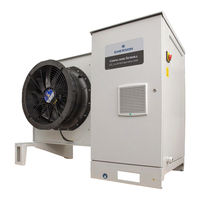
Emerson Copeland OME-16T Application Manuallines (58 pages)
Refrigeration Units
Brand:
Emerson
| Category:
Industrial Equipment
| Size: 4.27 MB
Table of Contents
Table of Contents
2
Safety Statements
6
About These Guidelines
6
Icon Explanation
6
Safety Instructions
6
General Instructions
7
Product Description
8
General Information about Copeland CO Scroll Refrigeration Unit
8
EU Ecodesign Directive 2009/125/EC
8
Main Product Features and Dimensions
9
Scroll Refrigeration Unit Technical Data
9
Scroll Refrigeration Unit Features
9
Figure 2: Dimensions of Copeland CO
9
Product Nameplate
10
Figure 3: Dimensions of Copeland CO
10
Figure 4: Nameplate of Copeland CO
10
Qualified Refrigerant and Oil
11
Figure 5: Nomenclature of Copeland CO2 Scroll Refrigeration Units
11
Application Range
11
Nomenclature
11
Application Limits
12
Recommendations for Minimum Suction Superheat - Lubrication Conditions
12
Pressure Levels of CO Vs. Other Refrigerants
12
Figure 6: Pressure Levels of CO
12
BOM Variations
13
Figure 7: Pressure/Enthalpy Diagram CO
13
Figure 8: P&I Diagram of CO Scroll Refrigeration Unit with Single Compressor
14
Figure 1: Copeland CO
14
Scroll Refrigeration Units with Single Compressor
14
Single-Compressor CO Scroll Refrigeration Units
14
P&I Diagrams
14
Tandem-Compressor CO Scroll Refrigeration Units
15
Scroll Refrigeration Units with Two Compressors
15
Figure 9: P&I Diagram of CO
15
Main Components Description
16
Compressor
16
Figure 10: Main Components of CO Scroll Ref Rigeration Unit (OME-16T)
16
Figure 11: Electrical Cabinet (OME-16T)
17
Fan
17
Liquid Receiver
17
Electrical Cabinet
17
High Pressure Valve (HPV)
18
Bypass Valve (BPV)
18
Liquid Injection Valve
18
Figure 12: Fan Design
18
Design Pressures
19
Housing
19
Figure 13: Design Pressures of Copeland CO2 Scroll Refrigeration Units
19
Figure 14: Overview of the Unit Housing
19
Figure 15: Liquid Line and Suction Line
20
Figure 16: Main Switch and Power Supply Cable Gland
20
CO Scroll Refrigeration Unit Control - General
21
XC Pro Controller Description
21
Visotouch Display Description
21
Figure 17: Copeland CO2 Scroll Refrigeration Unit Controller Schematics
21
Figure 18: Visotouch Display - Main Page
21
Figure 19: Visotouch Display - General Menu
22
Figure 22: PARAMETERS LEVEL 1 Page
23
Figure 21: PARAMETERS Page
23
Figure 20: Visotouch Display - Schematics
23
How to Use the XC Pro Controller
23
How to Change Parameters
23
How to Switch the XC Pro Controller On/Off
24
Figure 23: SETPOINTS Page
24
Figure 24: SERVICE Page
24
Figure 25: ON-OFF Page
24
Pumpdown Mode
25
Figure 26: Switching between Transcritical and Subcritical Mode
25
Suction Pressure Control
25
XC Pro Controller - Functionality
25
Fan Speed / Gas Cooler Control
26
Figure 27: Controller Logic for the Pumpdown Function with Factory Settings
26
Alarms
27
XC Pro Controller - Peripheral Devices
27
Variable Frequency Drive EVM
27
Figure 28: Alarm Button
27
Figure 29: Alarm Groups
27
Figure 30: XEV20D Stepper Valve Actuator
28
Compressor Motor Protection
28
Compressor Safety
28
Circuit Breakers
28
XEV20D Stepper Valve Actuator
28
High-Pressure Safety (Type-Approved Pressure Limiter)
29
Pressure Relief Valve - High-Pressure Side
29
Figure 31: High-Pressure Limiter
29
Figure 32: Pressure Relief Valve on High Pressure Side
29
High-Pressure Safety Control
29
Figure 33: Pressure Relief Valves with Changeover Valve on Liquid Receiver
30
Figure 34: Low Side Pressure Transmitter
30
Low-Pressure Safety Control
30
Pressure Relief Valve - Liquid Receiver
30
Figure 35: Sight Glass Level Control Zones
31
Figure 36: OM5 Traxoil Mounted on the Compressor
31
Oil Management Device - OM5 Traxoil
31
Installation
32
Refrigeration Unit Handling
32
Transport and Storage
32
Weights
32
Figure 37: Maximum Stacking Loads for Transport and Storage
32
Figure 38: Lifting Points for CO2 Scroll Refrigeration Units
33
Lifting
33
Refrigeration Piping Installation and Connections
33
Refrigeration Piping Connections
33
Service Ports
34
Figure 39: Piping Connections
34
Figure 40: Service Ports
34
Brazing Recommendations
35
Figure 41: Warning on Ports
35
Figure 42: Fully Opened Shut-Off Valve Rod
35
Figure 43: Fully Closed Shut-Off Valve Rod
35
Figure 44: Brazing - Sectional View
36
Pressure Testing at Suction Side
36
Electrical Connection
36
Power Supply Connections
37
Electrical Wiring
37
Electrical Protection Standard (Protection Class)
37
Figure 45: Power Supply Terminals with Jumper
37
Location & Fixings
38
Figure 46: Distances Required for Unit Installation (in MM)
38
Figure 47: Unit Mounted on Concrete Slab with Anti-Vibration Pads
39
Start-Up & Operation
40
Evacuation
40
Figure 48: General Menu
40
Charging Procedure
41
Refrigerant Charging Procedure
41
Oil Charging Procedure
42
Oil Separator
42
Rotation Direction of Scroll Compressors
42
Figure 49: Oil Separator
42
Maximum Compressor Cycle
43
Checks before Starting & During Operation
43
Maintenance & Repair
44
General Considerations
44
Opening the Unit Housing
44
To Open the Electrical Cabinet
44
Figure 50: Position of the Lock (OME-16T)
44
Figure 51: Opening the Compressor Chamber
45
Figure 52: Opening the Fan Safety Grid
45
To Remove the Fan Safety Grid
45
To Open the Compressor Chamber
45
Replacing a Compressor
46
Gas Cooler Fins
46
PRV Blow-Off
47
Regular Maintenance and Check
47
PRV Replacement on Liquid Receiver
47
Pressure Relief Valves
47
Gas Cooler Fan & Motor
47
Routine Leak Testing
47
Electrical Connections
47
Figure 53: Changeover Valve - Shaft in Open Position
48
Figure 54: Changeover Valve - Shaft in Closed Position
48
Certification & Approval
49
Dismantling & Disposal
49
Appendix 1: XC Pro Controller Alarm Menu
50
Appendix 2: Temperature / Resistance Curve for NTC
51
Appendix 3: Temperature / Resistance Curve for PTC
53
Appendix 4: Ecodesign Tables According to Regulation 2015/1095/EU
55
Appendix 5: List of Tables and Figures
56
Disclaimer
57
Related Products
Emerson Copeland OME-16T-TFD
Emerson Copeland OMTE-37T
Emerson Copeland OMTE-49T
Emerson Copeland OMTE-64T
Emerson Copeland OMTE-37T-TFD
Emerson Copeland OMTE-49T-TFD
Emerson Copeland OMTE-64T-TFD
Emerson Copeland EazyCool OME-4MTL-05X
Emerson Copeland EazyCool OME-4MTL-07X
Emerson Copeland EazyCool OME-4MTL-09X
Emerson Categories
Controller
Control Unit
Transmitter
Measuring Instruments
Fan
More Emerson Manuals