beautypg.com
Manuals
Brands
Emerson Manuals
Refrigerator
Copeland EazyCool OME-4MTL-05X
Emerson Copeland EazyCool OME-4MTL-05X Manuals
Manuals and User Guides for Emerson Copeland EazyCool OME-4MTL-05X. We have
2
Emerson Copeland EazyCool OME-4MTL-05X manuals available for free PDF download: Application Manuallines
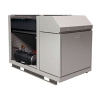
Emerson Copeland EazyCool OME-4MTL-05X Application Manuallines (72 pages)
Refrigeration Units for CO2 Applications
Brand:
Emerson
| Category:
Refrigerator
| Size: 4.31 MB
Table of Contents
Table of Contents
2
Figure 5: Pressure Levels of CO
2
About These Guidelines
6
Refrigeration Units
6
Safety Instructions
6
Safety Statements
6
Icon Explanation
6
General Instructions
7
Product Description
8
General Information about Copeland™ CO Refrigeration Units
8
EU Ecodesign Directive 2009/125/EC
8
Figure 1: Front View Copeland CO
8
Main Product Features and Dimensions
9
Figure 2: Dimensions of Models OME-4MTL-05X, OME-4MTL-07X, OME-4MTL-09X & OME
9
Figure 4: Nomenclature of CO
10
Nomenclature
10
Figure 3: Nameplate of CO
10
Product Nameplate
10
Application Range
11
Qualified Refrigerant and Oil
11
Application Limits
11
Recommendations for Minimum Suction Superheat - Lubrication Conditions
11
Pressure Levels of CO Vs. Other Refrigerants
12
Figure 6: Pressure/Enthalpy Diagram CO
12
Figure 7: P&I Diagram for CO Units
13
Units
13
P&I Diagram for CO Units
13
Compressor
14
Electrical Cabinet
14
Figure 8: Main Components of CO 2 Unit
14
Figure 9: Electrical Cabinet
14
Main Components Description
14
Liquid Receiver
15
Fan
15
Gas Cooler Regulation Valve (HPV)
15
Figure 10: Fan Design
15
Figure 11: Design Pressures of CO 2 Unit
16
Bypass Valve (BPV)
16
Design Pressures
16
Housing
17
Figure 12: Overview of the Unit Housing
17
Figure 13: Position of the Connections
17
Exploded View of the CO Unit
18
Figure 14: Exploded View of the Unit
18
Figure 16: Visograph Display
19
Figure 15: CO 2 Unit Controller Schematics
19
IPG215D Controller Description
19
Visograph Display Description
19
CO Unit Control - General
19
How to Use the IPG215D Controller
20
Figure 17: Parameter Key
20
Figure 18: Password Setting
20
How to Change Parameters
20
Parameter Grouping
21
Figure 19: Password Confirmation
21
Figure 20: Parameter Level Information
21
Service" Menu
22
How to Enter the "Service" Menu
22
Figure 21: "Service" Key
22
Figure 23: "Analog Outputs" Screen
23
Figure 24: "Loads Status" Screen
23
How to Check the Values of Analog Outputs
23
Figure 22: "Service" Menu
23
How to Check the Status of the Relays / Loads
23
How to Perform a Maintenance Using the "Compressors Service" Sub-Menus
24
Figure 25: "Compressor 1 Service" Menu
24
How to Check the Values of Digital Inputs
25
Figure 26: "Digital Inputs" Screen
25
Figure 27: "Probes" Menu
26
How to Set the Date and Time
26
How to Check the Values of the Probes
26
Controller Setting
27
Manual Compressor Run
27
Figure 28: "Real-Time Clock" Display
27
Figure 29: Manual Compressor Operation
27
How to Check the Operating Values of the Frequency Inverter M200
27
Data Logging
28
Figure 30: Reset to Factory Settings
28
How to Save User's Settings
28
How to Reset the Controller to Factory Settings
28
Active Alarm(S) Log Menu
29
Figure 31: Alarm Log
29
IPG215D Controller - Functionality
30
Suction Pressure Control
30
Figure 32: Switching from Transcritical to Subcritical Mode
30
Pumpdown Mode
31
Fan Speed / Gas Cooler Control
31
Figure 33: Controller Logic for the Pumpdown Function with Factory Settings
31
Figure 35: Alarm Flashing Symbol
32
Alarms
32
Figure 34: Sensoring in Subcritical Mode
32
Figure 36: "Alarm" Key
33
Figure 37: Active Alarms Screen
33
IPG215D Controller - Peripheral Devices
34
Variable Frequency Drive M200
34
XEV20D Stepper Valve Actuator
34
Main Contactor and Circuit Breakers
34
Figure 38: XEV20D Stepper Valve Actuator
34
Compressor Safety
35
High-Pressure Safety (Type-Approved Pressure Limiter)
35
High-Pressure Safety Control
35
Figure 39: Main Contactor and Circuit Breakers
35
Figure 40: High-Pressure Limiter
35
Compressor Motor Protection
35
Pressure Relief Valve - High-Pressure Side
36
Figure 41: Pressure Transmitters in the CO 2 Unit
36
Figure 42: Pressure Relief Valve on High-Pressure Side
36
Figure 44: Pressure Relief Valves with Changeover Valve
37
Figure 45: Low Side Pressure Transmitter
37
Figure 43: Liquid Receiver with Safety Group
37
Low-Pressure Safety Control
37
Pressure Relief Valve - Liquid Receiver
37
Oil Level Monitoring Device - OW5 Traxoil
38
Figure 46: Sight Glass Level Control Zones
38
Figure 47: OW5 Traxoil Mounted on the Compressor
38
Installation
39
Refrigeration Unit Handling
39
Transport and Storage
39
Weights
39
Figure 48: Maximum Stacking Loads for Transport and Storage
39
Figure 50: Lifting Unit with Slings and Centre of Gravity
40
Figure 49: Lifting Points for CO
40
Lifting
40
Refrigeration Piping Connections
41
Refrigeration Piping Installation and Connections
41
Figure 51: Piping Connections
41
Brazing Recommendations
42
Figure 52: Brazing - Sectional View
42
Electrical Connection
43
Power Supply Connections
43
Electrical Wiring
43
Figure 53: Power Supply Terminals with Jumper
43
Figure 54: Distances Required for Unit Installation (in MM)
44
Location & Fixings
44
Electrical Protection Standard (Protection Class)
44
Figure 55: Unit Mounted on Concrete Slab with Anti-Vibration Pads
45
Start-Up & Operation
46
Evacuation
46
Figure 56: Service Key
46
Figure 57: Evacuation Mode
47
Figure 58: Evacuation Mode
47
Maximum Compressor Cycle
48
Refrigerant Charging Procedure
48
Charging Procedure
48
Oil Charging Procedure
48
Checks before Starting & During Operation
49
Maintenance & Repair
50
General Considerations
50
Opening the Unit Housing
50
To Open the Electrical Cabinet
50
Figure 59: Position of the Locks
50
Figure 60: Opening the Compressor Chamber
51
Figure 62: Accessing the Inner Parts of the Unit
51
Figure 61: Opening the Fan Safety Grid
51
To Access the Inner Parts of the Gas Cooler
51
To Open the Compressor Chamber
51
To Remove the Fan Safety Grid
51
Replacing a Compressor
52
Gas Cooler Fins
52
Electrical Installation
53
Routine Leak Testing
53
Gas Cooler Fan & Motor
53
Pressure Relief Valves
53
PRV Blow-Off
53
Figure 63: Changeover Valve - Shaft in Open Position
54
Figure 64: Changeover Valve - Shaft in Closed Position
54
PRV Replacement on Liquid Receiver
54
Pressure Switch CS3
54
Regular Maintenance and Check
54
Certification & Approval
55
Dismantling & Disposal
55
Appendix 1: IPG215D Controller Alarm Menu
56
Appendix 2: Temperature / Resistance Curve for NTC
64
Appendix 3: Temperature / Resistance Curve for PTC
66
Appendix 4: Overview Tables - Regulation 2015/1095/EU
68
Appendix 5: List of Tables and Figures
70
Disclaimer
71
Emerson Copeland EazyCool OME-4MTL-05X Application Manuallines (71 pages)
CO2 Refrigeration Units
Brand:
Emerson
| Category:
Refrigerator
| Size: 4.44 MB
Table of Contents
Application Guidelines Copeland Eazycool ™ Co Refrigeration Units
2
Table of Contents
2
About These Guidelines
6
Icon Explanation
6
Safety Statements
6
General Instructions
7
1 Safety Instructions
6
2 Product Description
8
General Information about Copeland Eazycool™ CO Refrigeration Unit
8
EU Ecodesign Directive 2009/125/EC
8
Figure 1: Front View CO
8
Main Product Features
9
Figure 2: Dimensions of Models OME-4MTL-05X, OME-4MTL-07X & OME-4MTL-09X
9
Product Nameplate
10
Nomenclature
10
Figure 3: Nameplate of CO
10
Figure 4: Nomenclature of CO
10
Application Range
11
Qualified Refrigerant and Oil
11
Application Limits
11
Recommendations for Minimum Suction Superheat - Lubrication Conditions
11
Pressure Levels of CO Vs. Other Refrigerants
12
Figure 5: Pressure Levels of CO
12
Figure 6: Pressure/Enthalpy Diagram CO
12
Main Components Description
13
Compressor
13
Electrical Cabinet
13
Figure 7: Main Components of CO
13
Figure 8: Electrical Cabinet
13
Liquid Receiver
14
Fan
14
Condenser / Gas Cooler Regulation Valve (HPV)
14
Flashgas Bypass Valve (BPV)
14
Figure 9: Fan Design
14
Housing
15
Figure 10: Overview of the Unit Housing
15
Figure 11: Position of the Connections
15
Exploded View of the CO Unit
16
Figure 12: Exploded View of the Unit
16
P&I Diagram for CO Units
17
Design Pressures
17
Figure 13: P&I Diagram for CO
17
CO Unit Control - General
18
Figure 14: Design Pressures of CO
18
Figure 15: CO
18
Ipro IPR215D Controller Description
19
Visograph Display Description
19
Figure 16: Visograph Display
19
How to Use the Ipro IPR215D Controller
20
How to Change Parameters
20
Figure 17: Ipro Parameter Key
20
Figure 18: Password Setting
20
Figure 19: Password Confirmation
20
Parameter Grouping
21
Figure 20: Parameter Level Information
21
Service" Menu
22
How to Enter the "Service" Menu
22
Figure 21: Ipro "Service" Key
22
Figure 22: Ipro "Service" Menu
22
How to Check the Values of Analog Outputs
23
How to Check the Status of the Relays / Loads
23
Figure 23: Ipro "Analog Outputs" Screen
23
Figure 24: Ipro "Loads Status" Screen
23
How to Perform a Maintenance Using the "Compressors Service" Sub-Menus
24
Figure 25: "Compressor 1 Service" Menu
24
How to Check the Values of Digital Inputs
25
Figure 26: Ipro "Digital Inputs" Screen
25
How to Check the Values of the Probes
26
How to Set the Date and Time
26
Figure 27: Ipro "Probes" Menu
26
Figure 28: Ipro "Real-Time Clock" Display
26
How to Check the Operating Values of the Frequency Inverter M200
27
Controller Setting
27
Manual Compressor Run
27
Figure 29: Manual Compressor Operation
27
How to Reset the Controller to Factory Settings
28
How to Save User's Settings
28
Data Logging
28
Figure 30: Reset to Factory Settings
28
Active Alarm(S) Log Menu
29
Figure 31
29
Ipro IPR215D Controller - Functionality
30
Suction Pressure Control
30
Figure 32: Switching from Transcritical to Subcritical Mode
30
Pumpdown Mode
31
Fan Speed / Gas Cooler Control
31
Figure 33: Controller Logic for the Pumpdown Function
31
Alarms
32
Figure 34: Sensoring in Subcritical Mode
32
Figure 35: Ipro Alarm Flashing Symbol
32
Figure 36: Ipro "Alarm" Key
33
Figure 37: Active Alarms Screen
33
Ipro IPR215D Controller - Peripheral Devices
34
XEV20D Stepper Valve Actuator
34
Variable Frequency Drive M200
34
Main Contactor and Circuit Breakers
34
Figure 38: XEV20D Stepper Valve Actuator
34
Compressor Safety
35
Compressor Motor Protection
35
High-Pressure Safety (Type-Approved Pressure Limiter)
35
High-Pressure Safety Control
35
Figure 39: Main Contactor and Circuit Breakers
35
Figure 40: High-Pressure Cut-Out Device
35
Pressure Relief Valve - High-Pressure Side
36
Pressure Relief Valve - Liquid Receiver
36
Figure 41: Pressure Transmitters in the CO
36
Figure 42: Pressure Relief Valve on High-Pressure Side
36
Low-Pressure Safety Control
37
Figure 43: Liquid Receiver with Safety Group
37
Figure 44: Pressure Relief Valves with Changeover Valve
37
Figure 45: Low Side Pressure Transmitter
37
Oil Level Monitoring Device OW5 Traxoil
38
Figure 46: Sight Glass Level Control Zones
38
Figure 47: OW5 Traxoil Mounted on the Compressor
38
3 Installation
39
CO Refrigeration Unit Handling
39
Transport and Storage
39
Weights
39
Figure 48: Maximum Stacking Loads for Transport and Storage
39
Lifting
40
Figure 49: Lifting Points for CO
40
Figure 50: Lifting Unit with Slings and Centre of Gravity
40
Refrigeration Piping Connections
41
Refrigeration Piping Installation and Connections
41
Figure 51: Piping Connections
41
Brazing Recommendations
42
Figure 52
42
Electrical Connection
43
Power Supply Connections
43
Figure 53: Brazing - Sectional View
43
Electrical Wiring
44
Electrical Protection Standard (Protection Class)
44
Location & Fixings
44
Figure 54: Power Supply Terminals with Jumper
44
Figure 55: Dimensions and Distances Required for Unit Installation (in MM)
45
4 Start-Up & Operation
46
Evacuation
46
Figure 56: Service Key
46
Figure 57
47
Figure 58: Evacuation Mode
47
Charging Procedure
48
Refrigerant Charging Procedure
48
Oil Charging Procedure
48
Maximum Compressor Cycle
48
Checks before Starting & During Operation
49
5 Maintenance & Repair
50
Opening the Unit Housing
50
To Open the Electrical Cabinet
50
Figure 59: Position of the Locks
50
To Open the Compressor Chamber
51
To Remove the Fan Safety Grid
51
To Access the Inner Parts of the Condenser / Gas Cooler
51
Figure 60: Opening the Compressor Chamber
51
Figure 61: Opening the Fan Safety Grid
51
Figure 62: Accessing the Inner Parts of the Unit
51
Replacing a Compressor
52
Condenser Fins
52
Electrical Connections
53
Routine Leak Testing
53
Condenser Fan & Motor
53
6 Certification & Approval
53
7 Dismantling & Disposal
53
Disclaimer
54
Appendix 1: Alarm Menu Ipro IPR215D Controller
55
Appendix 2: Temperature / Resistance Curve for NTC
63
Appendix 3: Temperature / Resistance Curve for PTC
65
Appendix 4: Ecodesign Overview Tables According to Regulation 2015/1095/EU
67
Appendix 5: List of Tables and Figures
69
Related Products
Emerson Copeland EazyCool OME-4MTL-07X
Emerson Copeland EazyCool OME-4MTL-09X
Emerson Copeland OME-4MTL-12X
Emerson Copeland OMTE-76D
Emerson Copeland OMTE-152D
Emerson Copeland OLE-49
Emerson Copeland OLTE-82D
Emerson Copeland OME-16T
Emerson Copeland OME-16T-TFD
Emerson Copeland EazyCool OM-15-PFJ
Emerson Categories
Controller
Control Unit
Transmitter
Measuring Instruments
Fan
More Emerson Manuals