Table of Contents
Available languages
Available languages
Quick Links
Chapters
Table of Contents

Related Manuals for Honeywell ESSER 781443


Summary of Contents for Honeywell ESSER 781443
- Page 1 Installationsanleitung Installation Instruction Venturi-Lüftungskanalbausatz Venturi-Air Duct Kit (Art.-Nr. / Part No. 781443) 798349 Technische Änderungen vorbehalten! 04.2013 / AA Technical changes reserved! © 2013 Honeywell International Inc.
- Page 2 Venturi-Lüftungskanalbausatz Bestimmungsgemäßer Gebrauch Dieses Produkt darf nur für die im Katalog und in der technischen Beschreibung vorgesehenen Einsatzfälle und nur in Verbindung mit den empfohlenen bzw. zugelassenen Fremdgeräten und Komponenten verwendet werden. Warnung Der einwandfreie und sichere Betrieb des Produktes setzt sachgemäßen Transport, sachgerechte Lagerung, Aufstellung und Montage sowie sorgfältige Bedienung voraus.
-
Page 3: Table Of Contents
Venturi-Lüftungskanalbausatz Inhaltsverzeichnis Allgemein ..................................4 Montage..................................4 Montage auf dem Lüftungskanal........................5 Berechnung der Ein- und Auslaufstrecken ......................6 Montage Venturi-Rohrlänge bis 600 mm...................... 8 Montage Venturi-Rohrlänge von 600 - 2800 mm..................9 Venturi-Rohr anpassen ............................. 10 Venturi-Rohr montieren............................. 10 Montagesatz für runde und isolierte Lüftungskanäle .................. -
Page 4: Allgemein
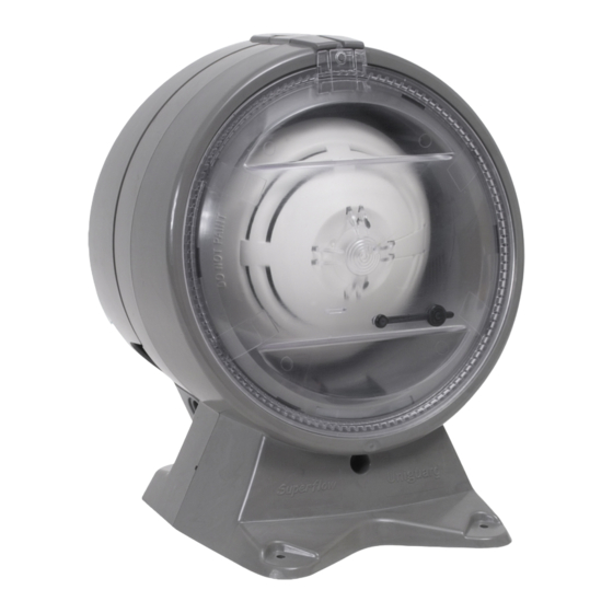
Venturi-Lüftungskanalbausatz Allgemein Der Venturi-Lüftungskanalbausatz (Art.-Nr. 781443) für spezielle IQ8Quad Brandmelder wird in Verbindung mit unterschiedlichen Venturi-Rohrlängen zur Überwachung von Lüftungskanälen ab einem Durchmesser von 100 mm in Gebäuden eingesetzt. Einsetzbare IQ8Quad Brandmelder: Art.-Nr. Bezeichnung blue 802379 IQ8Quad OT Der Bausatz wird von außen in Strömungsrichtung auf dem Lüftungskanal montiert und das Venturi-Rohr durch eine Bohrung in den Kanal eingeführt. -
Page 5: Montage Auf Dem Lüftungskanal
Venturi-Lüftungskanalbausatz Maße Abb. 1: Maße in mm Montage auf dem Lüftungskanal Die erforderliche Ausrichtung ist auf der Oberseite des Bausatzgehäuses durch ein Pfeilsymbol gekennzeichnet. Eine schnelle Orientierung bietet zusätzlich die Pfeilform des Befestigungsfußes. Lüftungskanalbausatz auf dem Lüftungskanal mit den drei beiliegenden, langen Schrauben an den drei vorgesehenen Befestigungspunkten montieren. -
Page 6: Berechnung Der Ein- Und Auslaufstrecken
Venturi-Lüftungskanalbausatz Berechnung der Ein- und Auslaufstrecken Rechteckiger Lüftungskanal Ringförmiger Lüftungskanal 2 x H x B H + B Um fehlerhafte Messungen auszuschließen, sollte der Lüftungskanalbausatz wie ein Durchflussmessgerät montiert werden. Für die Montage in unmittelbarer Nähe vor bzw. nach Drossel- und Regelklappen, Filtereinrichtungen oder bei Richtungsänderungen im Lüftungskanalsystem, sind folgende Mindestgrößen der Ein- und Auslaufstrecken einzuhalten: Einlaufstrecke... - Page 7 Venturi-Lüftungskanalbausatz Die nachfolgenden Diagramme zeigen unterschiedliche Anwendungsbeispiele sowie die zur Planung und Projektierung erforderlichen Ein-/Auslaufstrecken. MIN 3xd MIN 5xd MIN 3xd MIN 5xd Strömungs- Strömungs- Strömungs- Strömungs- richtung richtung richtung richtung Abb. 4: Ventilator Abb. 5: Drossel- bzw. Regelklappe MIN3xd MIN 5xd MIN 3xd MIN 5xd...
-
Page 8: Montage Venturi-Rohrlänge Bis 600 Mm
Venturi-Lüftungskanalbausatz Montage Venturi-Rohrlänge bis 600 mm Bei der Montage des Lüftungskanalbausatzes (mit oder ohne Montagesatz Art.-Nr. 781449) und einer Länge des Venturi-Rohres von max. 600 mm muss der Lüftungskanal an der oberen Stelle, wie in der Abbildung dargestellt, angebohrt werden. Montagehinweise! Öffnung (∅... -
Page 9: Montage Venturi-Rohrlänge Von 600 - 2800 Mm
Venturi-Lüftungskanalbausatz Montage Venturi-Rohrlänge von 600 - 2800 mm Bei der Montage des Lüftungskanalbausatzes (mit oder ohne Montagesatz) und einer Länge des Venturi- Rohres von mehr als 600 mm muss der Lüftungskanal an zwei Stellen, wie in der Abbildung dargestellt, angebohrt werden. Montagehinweise! Öffnungen in dem Lüftungskanal bohren und entgraten. -
Page 10: Venturi-Rohr Anpassen
Venturi-Lüftungskanalbausatz Venturi-Rohr anpassen Das Venturi-Rohr des Lüftungskanalbausatzes muss auf den Durchmesser des zu überwachenden Lüftungskanals angepasst werden. Hierzu stehen drei Venturi-Rohrlängen, die - falls erforderlich - eingekürzt werden können, zur Verfügung. Mindestdurchmesser des Lüftungskanals : 100 mm! Durchmesser des Lüftungskanals Venturi-Rohrlänge Art.-Nr. -
Page 11: Montagesatz Für Runde Und Isolierte Lüftungskanäle
Venturi-Lüftungskanalbausatz Montagesatz für runde und isolierte Lüftungskanäle Für die Montage des Lüftungskanalbausatzes auf isolierten und runden Lüftungskanälen ist grundsätzlich der optional erhältliche Montagesatz (Art.-Nr. 781449) zu verwenden. Zur flexiblen Anpassung an den Lüftungskanal kann dieser Montagesatz einfach in die gewünschte Form gebracht werden. Vorgestanzte Befestigungslöcher erleichtern die Montage. -
Page 12: Meldersockel Einsetzen
Venturi-Lüftungskanalbausatz Meldersockel einsetzen Einsetzbare Meldersockel Art.-Nr. Bezeichnung 805590 Meldersockel (Standard) 805591 Meldersockel mit Relaiskontakt Gehäuse auf der Melderseite öffnen: Gehäuse auf der Anschlussseite öffnen: 1. Kunststoffclip an der Gehäuseoberseite 1. Kunststoffclip an der Gehäuseoberseite vorsichtig mit einem schmalen Schraubendreher vorsichtig mit einem schmalen Schraubendreher anheben. -
Page 13: Meldersockel Anschließen
Venturi-Lüftungskanalbausatz Meldersockel anschließen An die Anschlussklemmen des eingesetzten Meldersockels (Art.-Nr. 805590 oder 805591) werden die farbigen Anschlusskabel des Lüftungskanalbausatzes angeschlossen (Zuordnung siehe Tabelle). Farbe des Klemme Meldersockel Anschlusskabels blau -ULin schwarz -ULout OUT5 +ULin OUT5 rosa +ULout gelb Ext. plus EP6* grün Ext. -
Page 14: Brandmelder Einsetzen
Venturi-Lüftungskanalbausatz Brandmelder einsetzen blue Der OT -LKM (Art.-Nr. 802379) wird mit dem Melderentnahmewerkzeug (Art.-Nr. 805580) lagerichtig auf den eingebauten Meldersockel aufgesetzt und mit einer Rechtsdrehung in den Sockel eingedreht. blue Der IQ8Quad OT -LKM wird über die Ringleitung des Brandmeldesystems mit der erforderlichen Betriebsspannung versorgt. -
Page 15: Endkontrolle
Venturi-Lüftungskanalbausatz Endkontrolle • Der Lüftungskanalbausatz ist ordnungsgemäß mit allen drei Befestigungsschrauben auf dem Lüftungskanal (bzw. dem Montagesatz) befestigt. • Die Umgebungs- und Betriebsbedingungen entsprechen den technischen Daten der eingesetzten Komponenten. • Der Richtungspfeil auf dem Lüftungskanalbausatz und die Strömungsrichtung in dem Lüftungskanal stimmen überein. -
Page 16: Wartung
Venturi-Lüftungskanalbausatz Wartung Bei Servicearbeiten an dem Brandmeldesystem bzw. dem Lüftungskanalmelder eine evtl. vorhandene Alarmweiterleitung, wie zum Beispiel die unbeabsichtigte Auslösung einer Übertragungseinrichtung (ÜE), beachten! Zur Überprüfung des Melders, die Meldergruppe an der Brandmelderzentrale in den Prüfbetrieb schalten. Dazu entsprechende Hinweise in der Dokumentation der angeschlossenen Brandmelderzentrale beachten. 1. -
Page 17: Technische Daten
Venturi-Lüftungskanalbausatz Technische Daten Bausatzgehäuse (Art.-Nr. 781443) Anschlussklemmen max. 1,5 mm² Umgebungstemperatur -10 °C bis +60 °C Lagertemperatur -15 °C bis +65 °C Schutzart IP 54 Material / Gehäuse ABS-Kunststoff Farbe grau (mit transparenter Blende) Gewicht ca. 800 g (ohne Melder / Meldersockel) Maße (B x H x T) 180 x 235 x 183 (mm) Optional:... -
Page 18: Zubehör
Venturi-Lüftungskanalbausatz Zubehör Bezeichnung Art.-Nr. Ersatzfilter 781444 Wetterschutzgehäuse für Außenmontage 781445 Venturi-Rohr 600 mm 781446 Venturi-Rohr 1500 mm 781447 Venturi-Rohr 2800 mm 781448 Montagesatz für runde und isolierte Lüftungskanäle 781449 blue IQ8Quad OT -LKM 802379 IQ8Quad Meldersockel (Standard) 805590 IQ8Quad Meldersockel mit Relaiskontakt 805591 Wetterschutzgehäuse für Außenmontage (Art.-Nr. -
Page 19: Anschaltung An Bmz
Venturi-Lüftungskanalbausatz Anschaltung an BMZ Venturi-Lüftungskanalbausatz 781443 Venturi-Lüftungskanalbausatz 781443 Meldersockel 805590 (Standard) mit Meldersockel 805590 (Standard) mit Meldersockel 805591 (Relais) Option max. 100 m OUT5 1 2 3 4 5 6 7 8 1 2 3 4 5 6 7 8 IN4 / B - C3 / B + Abb. - Page 20 Venturi-Lüftungskanalbausatz Notizen FB 798349 / 04.13...
- Page 21 Installation Instruction Venturi-Air Duct Kit (Part No. 781443) 798349 Technical changes reserved! 04.2013 / AA © 2013 Honeywell International Inc.
- Page 22 Venturi-Air Duct Kit Intended purpose This product must only be used for the applications outlined in the catalogue and the technical description and in combination with external components and systems which have been approved. Warning In order to ensure correct and safe operation of the product, all guidelines concerning its transport, storage, installation, and mounting must be observed.
- Page 23 Venturi-Air Duct Kit Table of contents General ..................................24 Mounting ................................... 24 10.1 Mounting the air duct kit..........................25 10.2 Calculation of upstream and downstream distances.................. 26 10.3 Mounting Venturi tubes up to 600 mm ....................28 10.4 Mounting Venturi tubes between 600 mm and 2800 mm..............29 10.5 Adapt the Venturi tube length........................
-
Page 24: General
Venturi-Air Duct Kit General The air duct kit (Part No. 781443) is used in combination with different Venturi tubes and special IQ8Quad fire detectors for the surveillance of air ducts with a diameter from 100 mm in buildings. Suitable IQ8Quad fire detectors: Part No. -
Page 25: Mounting The Air Duct Kit
Venturi-Air Duct Kit Dimensions Fig. 1: Dimensions in mm 10.1 Mounting the air duct kit The required mounting position is indicated by the arrow on the top of the enclosure. The arrow shaped bottom of the enclosure provides a quick info for the correct positional arrangement of the air duct kit. Mount the kit with the supplied three long screws on the duct. -
Page 26: Calculation Of Upstream And Downstream Distances
Venturi-Air Duct Kit 10.2 Calculation of upstream and downstream distances Air duct with circular cross-section Air duct with rectangular cross-section 2 x H x B H + B In order to exclude faulty measurements the air duct detector should be mounted in the same way as a flow meter. - Page 27 Venturi-Air Duct Kit Different application samples for the air duct mounting are shown in following diagrams to calculate the required air inlet/exhaust sections. MIN 3xd MIN 5xd MIN 3xd MIN 5xd Direction Direction Direction Direction of air flow of air flow of air flow of air flow Fig.
-
Page 28: Mounting Venturi Tubes Up To 600 Mm
Venturi-Air Duct Kit 10.3 Mounting Venturi tubes up to 600 mm To mount the air duct (with or without the optional mounting kit Part No. 781449) with a pipe length of max. 600 mm the air duct must be drilled as shown in the figure. Mounting information! Drill a hole (∅... -
Page 29: Mounting Venturi Tubes Between 600 Mm And 2800 Mm
Venturi-Air Duct Kit 10.4 Mounting Venturi tubes between 600 mm and 2800 mm To mount the air duct (with or without the optional mounting kit Part No. 781449) with a pipe length of more than 600 mm the air duct must be drilled at two points as shown in the figure. Mounting information! Drill a hole (∅... -
Page 30: Adapt The Venturi Tube Length
Venturi-Air Duct Kit 10.5 Adapt the Venturi tube length The Venturi tube of the air duct kit has to be adapted to the diameter of the air duct system. Venturi tubes are available in three different lengths which can then be cut - if needed - to the required length. Minimum diameter of the air ducts: 100 mm. -
Page 31: Mounting Kit For Circular And Insulated Air Duct Systems
Venturi-Air Duct Kit 10.7 Mounting kit for circular and insulated air ducts The mounting kit (Part No. 781449, option) has to be used for mounting on insulated or circular air duct systems. The mounting kit can simply be bend to fit to the shape of the duct. Pre-punched mounting holes are provided for easy installation. -
Page 32: Install Detector Base
Venturi-Air Duct Kit Install detector base Available Detector bases Part No. Discription 805590 Detector base (standard) 805591 Detector base with relay contact Open enclosure on the detectors side: Open enclosure on the terminals side: 1. Lift plastic tab at the top carefully upwards with 1. -
Page 33: Detector Base Wiring
Venturi-Air Duct Kit 11.1 Detector base wiring The coloured connection cable of the air duct kit must be connected to the terminals of the detector base (Part No. 805590 or 805591) (refer to table). Cable Colour Terminal Detector base blue -ULin black -ULout... -
Page 34: Install Fire Detector
Venturi-Air Duct Kit 11.2 Install fire detector blue The OT -LKM (Part No. 802379) must be aligned to the detector base and mounted by turning the detector clockwise into the base until it engages. It is recommended to use the removal tool (Part No. 805580) to insert/remove the detector from the base. -
Page 35: Final Check
Venturi-Air Duct Kit Final check • The air duct kit must be fastened correctly on the air duct by using the supplied three screws (or optional mounting kit). • The ambient conditions must match the specifications of the components. • The arrow head on the air duct kit must point into the direction of the air flow inside the air duct. -
Page 36: Maintenance
Venturi-Air Duct Kit Maintenance If the air duct kit or the FACP is undergoing service and maintenance work observe that no unwanted alarms are activated and disconnect the master box (alarm transmission unit) if present. To test the air duct detector enabled the test operation mode for this detector zone at the panel! Observe the related informations in the manual of the Fire Alarm Control Panel. -
Page 37: Specifications
Venturi-Air Duct Kit Specifications Air duct detector housing (Part No. 781443) Terminals 1.5 mm² max. Air velocity 1 m/s to 20 m/s Ambient temperature -10 °C to +60 °C Storage temperature -15 °C to +65 °C Protection class IP 54 Housing ABS plastic Colour... -
Page 38: Accessories
Venturi-Air Duct Kit Accessories Description Part No. Air duct kit 781443 Replacement filter 781444 Weather protective cover for outdoor installation 781445 Venturi tube 600 mm 781446 Venturi tube 1500 mm 781447 Venturi tube 2800 mm 781448 Mounting kit for circular and insulated air ducts 781449 blue IQ8Quad OT... -
Page 39: Wiring To The Facp
Venturi-Air Duct Kit Wiring to the FACP Venturi-Air Duct Kit 781443 Venturi-Air Duct Kit 781443 detector base 805590 (standard) with detector base 805590 (standard) with detector base 805591 (relay) option max. 100 m OUT5 1 2 3 4 5 6 7 8 1 2 3 4 5 6 7 8 IN4 / B - C3 / B +... - Page 40 Novar GmbH a Honeywell Company Dieselstraße 2, D-41469 Neuss Telefon: +49 (0) 21 37 / 17-0 Verwaltung Internet: www.esser-systems.de +49 (0) 21 37 / 17-600 E-Mail: [email protected] Telefax: +49 (0) 21 37 / 17-286...