Table of Contents
Quick Links
Table of Contents

Related Manuals for Honeywell 10288


Summary of Contents for Honeywell 10288
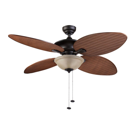
- Page 1 SUNSET KEY 52” CEILING FAN MODEL #10288 Español p. 21 RATED FOR DAMP LOCATION Questions, problems, missing parts? Before returning to your retailer, call our customer service department at 1-877-361-3883, Monday - Thursday, 8 am - 6 pm, EST and Friday,...
-
Page 2: Table Of Contents
WELCOME TABLE OF CONTENTS PREPARATION Before beginning the assembly of this product, ensure Care and Maintenance ......2 that all parts are present. -
Page 3: Package Contents
PACKAGE CONTENTS Unpack your fan and check the contents. You should have the following items: 1. Blade (4) 2. Mounting Bracket 3. Canopy 4. Canopy Cover 5. Yoke Cover 6. Downrod 7. Downrod Pin 8. Downrod Clip 9. Blade Arm (4) 10. -
Page 4: Safety Information
SAFETY INFORMATION Please read and understand this entire manual before attempting to assemble, operate, or install the product. • Before you begin installing the fan, disconnect the power by removing fuses or turning off the circuit breakers. • Make sure that all electrical connections comply with local codes, ordinances, the National Electrical Code, and ANSI/NFPA 70-199. -
Page 5: Mounting Options
MOUNTING OPTIONS 1. Your fan has 3 mounting options: Fig. 1 • Standard (Fig. 1) • Angle (Fig. 2) • Closemount (Fig. 3) Note: The fans in figures 1 through 3 are not the actual fan in your package, they are representation of the 3 different mounting options. -
Page 6: Mounting Bracket Installation
MOUNTING BRACKET INSTALLATION 4. Turn off the circuit breakers and wall switch leading Fig. 4 to the fan wire leads. WARNING Failure to disconnect the power supply prior to installation may result in serious injury or death. 5. Loosen all four pre-assembled mounting bracket Fig. -
Page 7: Standard Or Angle Mounting Instructions
STANDARD OR ANGLE MOUNTING INSTRUCTIONS 7. Partially loosen the two set screws in the yoke at Fig. 7 the top of the motor assembly (Fig. 7). Set Screws Fig. 8 8. Remove the downrod clip and downrod pin from the downrod (Fig. 8). Downrod Clip Downrod Pin... - Page 8 STANDARD OR ANGLE MOUNTING INSTRUCTIONS 10. Slide the downrod into the yoke of the motor Fig. 10 assembly, align the holes, and re-install the downrod pin and downrod clip. Then re-tighten the two set screws (Fig. 10). Downrod Downrod Downrod Clip Yoke 11.
- Page 9 STANDARD OR ANGLE MOUNTING INSTRUCTIONS 13. Install the ball end of the downrod into the Fig. 13 mounting bracket opening. Align the slot in the ball with the tab in the mounting bracket. The downrod should not rotate if installed correctly (Fig. 13). Mounting Slot WARNING...
-
Page 10: Closemount Instructions
CLOSEMOUNT INSTRUCTIONS 14. Remove the canopy cover from the bottom of the Fig. 14 canopy (Fig. 14). Helpful Hint: The downrod, yoke cover and canopy cover are not used in this type of installation. Canopy Cover Canopy 15. Align the canopy with the holes in the top of motor Fig. -
Page 11: Wiring
WIRING CAUTION Fig. 17 Be sure outlet box is properly grounded or that a ground (green or bare) wire is present. Black (Hot) WARNING If house wires are different colors than referred to in White (Neutral) the following steps, consult a professional electrician Bare/Green (Ground) to determine wiring. -
Page 12: Canopy Installation
CANOPY INSTALLATION 19. Lift the canopy up until the partially installed Fig. 19 mounting bracket screws are engaged in the J-slots on each side of the canopy. Rotate the canopy clockwise and install the previously removed mounting bracket screws from Step 5. Tighten all four mounting bracket screws (Fig. -
Page 13: Blade Installation
BLADE INSTALLATION 20. Remove motor screws, motor blocks and washers Fig. 19 Fig. 20 from underside of the motor assembly. Discard the motor blocks and washers but keep the motor screws for blade arm attachment. (Fig. 20). Motor Block Washer Motor Screw Motor Screw Motor Block... -
Page 14: Light Kit Installation
LIGHT KIT INSTALLATION 23. To install the fan with the light kit: Fig. 23 Remove the three fitter plate screws from fitter plate. Then connect the 9-pin connectors from the motor assembly and the light kit. Ensure the plugs Fitter Plate are connected tightly (Fig. - Page 15 LIGHT KIT INSTALLATION 26. Install the candelabra-base A15 bulbs (Fig. 26). Fig. 26 Bulb 27. Feed the fan pull chain from the switch housing Fig. 27 through the off-center hole in the glass bowl. Then, feed the pull chain from the light kit through the center hole in the glass bowl, rubber washer and Switch Housing hex nut (Fig.
- Page 16 LIGHT KIT INSTALLATION 29. (Optional) To install the fan without the light kit: Hex Nut Fig. 29 Washer Unscrew the hex nut and washer from the threaded rod in the switch housing to remove the light kit and wiring (Fig. 29). Switch Housing Light Kit...
-
Page 17: Operating Instructions
OPERATING INSTRUCTIONS 32. Use the reverse switch, located on the side of the Fig. 32 fan, to optimize your fan for seasonal performance (Fig. 32). Using a ceiling fan will allow you to raise your thermostat in the summer and lower your thermostat in the winter without sacrificing comfort. -
Page 18: Replacement Parts List
REPLACEMENT PARTS LIST For replacement parts, call the customer service department at 1-877-361-3883, 8 a.m. - 6 p.m., EST, Monday - Thursday, 8 a.m. - 5 p.m., EST, Friday. MODEL 10288 PIECE DESCRIPTION PART # Blade Arm 10288-A Blade 10288-B... -
Page 19: Troubleshooting
TROUBLESHOOTING At least twice each year, lower the canopy to check the downrod assembly, and then tighten all screws on the fan. Clean the motor housing with only a soft brush or lint-free cloth to avoid scratching the finish. Clean the blades with a lint-free cloth. You may occasionally apply a light coat of furniture polish to wood blades for added protection. -
Page 20: Limited Lifetime Warranty
1-877-361-3883 Monday - Thursday, 8 am - 6 pm, EST and Friday, 8 am - 5 pm, EST. Please have a copy of the receipt as proof of purchase. The Honeywell Trademark is used under license from Honeywell International Hong Kong China Electric Appliance Manufacture Co., Ltd.