Table of Contents

Related Manuals for Honeywell Bonterra


Summary of Contents for Honeywell Bonterra
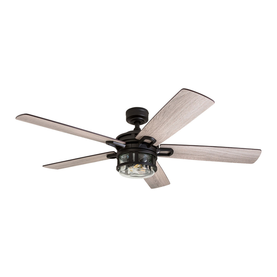
- Page 1 Home Bonterra Ceiling Fan User Guide Model #50610, 50690...
-
Page 2: Package Contents
PACKAGE CONTENTS Canopy Canopy Cover Mounting Bracket Screw (x 4) Mounting Bracket Downrod Downrod Clip Downrod Pin Yoke Cover Set Screw (x 2) Closemount Screw (x 3) Yoke Motor Assembly Blade (x 5) Blade Arm (x 5) Light Pan Light Kit Bulb (x 3) Remote Pack Glass Bowl... -
Page 3: Safety Information
SAFETY INFORMATION Please read and understand this entire manual before attempting to assemble, operate or install the product. • Before you begin installing the fan, disconnect the power by removing fuses or turning off the circuit breakers. • Make sure all electrical connections comply with local codes, ordinances, the National Electrical Code and ANSI/NFPA 70-199. -
Page 4: Initial Installation
PREPARATION Before beginning the assembly of this product, ensure all parts are present. Compare all parts with the package contents list and hardware contents list. If any part is missing or damaged, do not attempt to assemble the product. Estimated assembly time: 2 hours Tools required (not included): Electrical tape, Phillips Screwdriver, Safety Glasses, Step Ladder, and Wire Strippers. - Page 5 STANDARD OR ANGLE MOUNT INSTRUCTIONS 1. Remove the downrod pin and downrod clip from the downrod. Then, loosen but don’t remove the two set screws in the yoke (Figure 3.1). 2. Feed the fan wires through the yoke cover, canopy and downrod (Figure 3.2). 3.
-
Page 6: Final Installation
CLOSEMOUNT INSTRUCTIONS (optional) 1. Remove the canopy cover from the bottom of the canopy (Figure 4.1). 2. Remove the three Phillips-head closemount screws from the top of the motor assembly. Then align the canopy with the holes in the top of the motor assembly. The larger holes in the canopy will encompass the remaining screws. Secure the canopy to the top of the motor assembly with the previously removed closemount screws (Figure 4.2). - Page 7 FINAL INSTALLATION 4. Partially insert three blade screws, along with the blade washers, through the blade and into the blade arm. Tighten each blade screw, starting with the one in the middle. Repeat this step for the remaining blades and blade arms (Figure 5.4). 5.
- Page 8 FINAL INSTALLATION 10. Remove the battery door from the back of the remote. Insert the battery from the remote pack into the remote; ensure polarity of the battery matches the polarity indicated in the battery compartment -- positive (+) to positive (+) and negative (-) to negative (-).
-
Page 9: Troubleshooting
TROUBLESHOOTING If you experience any faults, please check the Troubleshooting section below. If a problem cannot be remedied or you are experiencing difficulty in installation, please contact Customer Service: 1-877-361-3883. Warning: Shut off the power supply before you begin any maintenance task. PROBLEM CORRECTIVE ACTION 1. -
Page 10: Limited Lifetime Warranty
4L000008000 4A000009830 Mounting Bracket 4L000006410 4L000006350 Downrod 4A000003980 4L000008650 Light Kit 4A000008540 4A000009840 The Honeywell Trademark is used under license Glass Bowl 4A166520000 4A166520000 from Honeywell International Inc ™. Remote Pack 4A000008300 4A000008300 Honeywell International Inc. makes no representations or warranties with respect to this...