Dell OptiPlex Small Form Factor 7010 Owner's Manual
Hide thumbs
Also See for OptiPlex Small Form Factor 7010:
- Owner's manual (119 pages) ,
- Owner's manual (119 pages) ,
- Owner's manual (119 pages)

Related Manuals for Dell OptiPlex Small Form Factor 7010


Summary of Contents for Dell OptiPlex Small Form Factor 7010
- Page 1 OptiPlex Small Form Factor 7010 Owner's Manual Regulatory Model: D17S Regulatory Type: D17S003 March 2023 Rev. A00...
- Page 2 A WARNING indicates a potential for property damage, personal injury, or death. © 2023 Dell Inc. or its subsidiaries. All rights reserved. Dell Technologies, Dell, and other trademarks are trademarks of Dell Inc. or its subsidiaries. Other trademarks may be trademarks of their respective owners.
-
Page 3: Table Of Contents
Contents Chapter 1: Views of OptiPlex Small Form Factor 7010..............6 Display.....................................7 Back......................................9 Chapter 2: Set up your computer....................11 Chapter 3: Specifications of OptiPlex Small Form Factor 7010............. 18 Dimensions and weight..............................18 Processor..................................... 18 Chipset....................................20 Operating system................................20 Memory....................................20... - Page 4 Side cover....................................37 Removing the side cover............................37 Installing the side cover............................. 38 Front bezel ..................................38 Removing the front bezel............................38 Installing the front bezel............................39 Hard drive....................................40 2.5-inch hard drive..............................40 3.5-inch hard drive..............................43 Disk-drive cage.................................. 47 Removing the disk-drive cage..........................47 Installing the disk-drive cage............................
- Page 5 Deleting or changing an existing system setup password................113 Clearing BIOS (System Setup) and System passwords..................114 Chapter 9: Troubleshooting......................115 Dell SupportAssist Pre-boot System Performance Check diagnostics...............115 Running the SupportAssist Pre-Boot System Performance Check............... 115 Power-Supply Unit Built-in Self-Test .........................115 System-diagnostic lights..............................
-
Page 6: Chapter 1: Views Of Optiplex Small Form Factor 7010
Views of OptiPlex Small Form Factor 7010... -
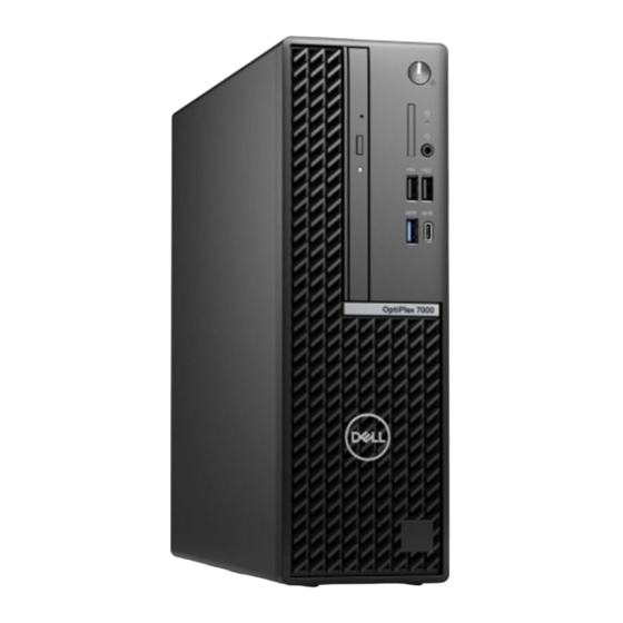
Page 7: Display
Views of OptiPlex Small Form Factor 7010 Display Views of OptiPlex Small Form Factor 7010... - Page 8 1. Power button with diagnostic LED 2. Hard-drive activity light 3. Universal audio jack port 4. Two USB 2.0 ports 5. Two USB 3.2 Gen 1 ports 6. Slim optical drive Views of OptiPlex Small Form Factor 7010...
-
Page 9: Back
Back Views of OptiPlex Small Form Factor 7010... - Page 10 9. RJ45 Ethernet port 10/100/1000 Mbps 10. External antenna connector (optional) 11. One Security-cable slot (for Kensington locks) 12. One video port (HDMI 2.1/Displayport 1.4a (HBR3)/VGA) (optional) 13. Service Tag label 14. One Serial port (optional) Views of OptiPlex Small Form Factor 7010...
-
Page 11: Chapter 2: Set Up Your Computer
Set up your computer Steps 1. Connect the keyboard and mouse. Set up your computer... - Page 12 2. Connect to your network using a cable, or connect to a wireless network. Set up your computer...
- Page 13 3. Connect the display. Set up your computer...
- Page 14 4. Connect the power cable. Set up your computer...
- Page 15 5. Press the power button. Set up your computer...
- Page 16 6. Finish operating system setup. Set up your computer...
- Page 17 Follow the on-screen instructions to complete the setup. For more information about installing and configuring Ubuntu, search in the Knowledge Base Resource at www.dell.com/support. For Windows: Follow the on-screen instructions to complete the setup. When setting up, Dell recommends that you: ● Connect to a network for Windows updates. NOTE: If connecting to a secured wireless network, enter the password for the wireless network access when prompted.
-
Page 18: Chapter 3: Specifications Of Optiplex Small Form Factor 7010
Specifications of OptiPlex Small Form Factor 7010 Dimensions and weight The following table lists the height, width, depth, and weight of your OptiPlex Small Form Factor 7010. Table 2. Dimensions and weight Description Values Height 290.00 mm (11.42 in.) Width 92.60 mm (3.65 in.) - Page 19 24 MB 24 MB 4 MB 6 MB Integrated Intel UHD Intel UHD Intel UHD Intel UHD Intel UHD Intel UHD graphics Graphics 730 Graphics 730 Graphics 770 Graphics 770 Graphics 710 Graphics 710 Specifications of OptiPlex Small Form Factor 7010...
-
Page 20: Chipset
Chipset The following table lists the details of the chipset supported by your OptiPlex Small Form Factor 7010. Table 4. Chipset Description Values Chipset Intel Q670 Processor Intel Core i3/i5/Intel Celeron/Pentium DRAM bus width 64-bit/128-bit Flash EPROM 32 MB RPMC+16 MB nRPMC... -
Page 21: Memory Matrix
Memory matrix The following table lists the memory configurations supported on your OptiPlex Small Form Factor 7010. Table 6. Memory matrix Configuration Slot DIMM1 DIMM2 4 GB DDR4 4 GB 8 GB DDR4 8 GB 8 GB DDR4 4 GB... -
Page 22: Internal Slots
SATA slots Two SATA 3.0 slots for 2.5-inch/3.5-inch hard drive and slim optical drive Ethernet The following table lists the wired Ethernet Local Area Network (LAN) specifications of your OptiPlex Small Form Factor 7010. Table 9. Ethernet specifications Description Values... -
Page 23: Audio
● TKIP ● TKIP Bluetooth Bluetooth wireless card Bluetooth wireless card Bluetooth wireless card Audio The following table lists the audio specifications of your OptiPlex Small Form Factor 7010. Table 11. Audio specifications Description Values Audio controller Realtek ALC3246-CG Stereo conversion... -
Page 24: Power Ratings
M.2 2230 solid-state drive, Class 25 PCIe NVMe, up to 64 Gbps Up to 1 TB Power ratings The following table lists the power rating specifications of OptiPlex Small Form Factor 7010. Table 14. Power ratings Description Option one Option two... -
Page 25: Power Supply Connector
-40°C to 70°C (-40°F to 158°F) -40°C to 70°C (-40°F to 158°F) Power supply connector The following table lists the Power supply connector specifications of your OptiPlex Small Form Factor 7010. Table 15. Power supply connector 180 W (80 Plus Bronze) ●... -
Page 26: Gpu-Discrete
DisplayPort Multi-Stream Transport (MST) allows you to daisy chain monitors that have DisplayPort 1.2 and above ports and MST support. For more information about using DisplayPort Multi-Stream Transport, see www.dell.com/support. Hardware security The following table lists the hardware security of your OptiPlex Small Form Factor 7010. Table 20. Hardware security Hardware security... -
Page 27: Environmental
Dell Regulatory Compliance Home Page Dell and the Environment Operating and storage environment This table lists the operating and storage specifications of your OptiPlex Small Form Factor 7010. Airborne contaminant level: G1 as defined by ISA-S71.04-1985 Table 23. Computer environment... - Page 28 Operating and storage temperature ranges may differ among components, so operating or storing the device outside these ranges may impact the performance of specific components. * Measured using a random vibration spectrum that simulates user environment. † Measured using a 2 ms half-sine pulse. Specifications of OptiPlex Small Form Factor 7010...
-
Page 29: Chapter 4: Working Inside Your Computer
You should only perform troubleshooting and repairs as authorized or directed by the Dell technical assistance team. Damage due to servicing that is not authorized by Dell is not covered by your warranty. See the safety instructions that is shipped with the product or at www.dell.com/regulatory_compliance. -
Page 30: Safety Precautions
ESD protection is an increasing concern. Due to the increased density of semiconductors used in recent Dell products, the sensitivity to static damage is now higher than in previous Dell products. For this reason, some previously approved methods of handling parts are no longer applicable. -
Page 31: Esd Field Service Kit
Always place parts in your hand, on the ESD mat, in the system, or inside an anti-static bag. ● Transporting Sensitive Components – When transporting ESD sensitive components such as replacement parts or parts to be returned to Dell, it is critical to place these parts in anti-static bags for safe transport. Working inside your computer... -
Page 32: Transporting Sensitive Components
Transporting sensitive components When transporting ESD sensitive components such as replacement parts or parts to be returned to Dell, it is critical to place these parts in anti-static bags for safe transport. -
Page 33: Screw List
● Phillips screwdriver #0 ● Phillips screwdriver #1 ● Torx #5 (T5) screwdriver ● Plastic scribe Screw list NOTE: When removing screws from a component, it is recommended to note the screw type, the quantity of screws, and then place them in a screw storage box. This is to ensure that the correct number of screws and correct screw type is restored when the component is replaced. -
Page 34: Major Components Of Optiplex Small Form Factor 7010
Table 24. Screw list (continued) Component Screw type Quantity Screw image System board #6-32 Major components of OptiPlex Small Form Factor 7010 The following image shows the major components of OptiPlex Small Form Factor 7010. Working inside your computer... - Page 35 Working inside your computer...
- Page 36 13. Processor 14. Speaker NOTE: Dell provides a list of components and their part numbers for the original system configuration purchased. These parts are available according to warranty coverages purchased by the customer. Contact your Dell sales representative for purchase options.
-
Page 37: Chapter 5: Removing And Installing Customer Replaceable Units (Crus)
Removing and installing Customer Replaceable Units (CRUs) The replaceable components in this chapter are Customer Replaceable Units (CRUs). CAUTION: Customers can replace only the Customer Replaceable Units (CRUs) following the safety precautions and replacement procedures. NOTE: The images in this document may differ from your computer depending on the configuration you ordered. Side cover Removing the side cover Prerequisites... -
Page 38: Installing The Side Cover
Installing the side cover Prerequisites If you are replacing a component, remove the existing component before performing the installation procedure. About this task The following image indicates the location of the side cover and provides a visual representation of the installation procedure. Steps 1. -
Page 39: Installing The Front Bezel
Steps 1. Gently pry and release the front-bezel tabs sequentially from the top. 2. Rotate the front bezel outward from the chassis and remove the front bezel. Installing the front bezel Prerequisites If you are replacing a component, remove the existing component before performing the installation procedure. About this task The following images indicate the location of the front bezel and provides a visual representation of the installation procedure. -
Page 40: Hard Drive
Steps 1. Align the front-cover tabs with the slots on the chassis. 2. Rotate the front cover towards the chassis and snap it into place. Next steps 1. Install the side cover. 2. Follow the procedure in After working inside your computer. - Page 41 About this task The following image indicates the location of the 2.5-inch hard-drive assembly and provide a visual representation of the removal procedure. Steps 1. Disconnect the data and power cables from the hard drive. Removing and installing Customer Replaceable Units (CRUs)
- Page 42 2. Remove the screw (#6-32) that secures the hard drive carrier to the chassis. 3. Remove the four screws (M3x3.5) that secure the hard drive to the hard-drive carrier. 4. Slide and lift the 2.5-inch hard drive off the hard-drive carrier. NOTE: Note the orientation or the SATA connector marking on the hard-drive carrier so that you can replace it correctly.
-
Page 43: 3.5-Inch Hard Drive
Steps 1. Insert and align the hard drive into the hard-drive carrier. 2. Replace the four screws (M3x3) that secure the hard drive to the hard-drive carrier. 3. Align the tabs on the hard-drive carrier with the slots on the chassis and snap the hard-drive carrier into place. 4. - Page 44 Removing and installing Customer Replaceable Units (CRUs)
- Page 45 Steps 1. Disconnect the data and power cables from the hard drive. 2. Remove the two screws (6-32) that secure the hard-drive carrier to the chassis. 3. Slide the hard-drive carrier away from the chassis and lift hard-drive carrier out of the disk-drive cage. 4.
- Page 46 Removing and installing Customer Replaceable Units (CRUs)
-
Page 47: Disk-Drive Cage
Steps 1. Slide the hard drive into the hard-drive carrier. 2. Replace the two screws (6-32) to secure the hard drive to the hard-drive carrier. 3. Align the tabs on the hard-drive carrier with the slots on the chassis and snap the hard-drive carrier onto the disk-drive cage. - Page 48 About this task The following image indicates the location of the disk-drive cage and provides a visual representation of the removal procedure. Removing and installing Customer Replaceable Units (CRUs)
-
Page 49: Installing The Disk-Drive Cage
Steps 1. If the optical drive is installed, remove the data and power cables from the routing points on the disk-drive cage. 2. Remove the single (6-32) screw to release the disk-drive cage from the chassis.. 3. Lift the disk-drive and detach it from the mounting points on the chassis. 4. - Page 50 Removing and installing Customer Replaceable Units (CRUs)
-
Page 51: Optical Drive
Steps 1. Place the disk-drive cage upside down on the chassis. 2. If the optical drive is installed, connect the data and power cable to the connectors on the optical drive. 3. Hold the disk-drive cage upright and align the mounting points on the disk-drive cage with the slots on the chassis. 4. -
Page 52: Installing The Optical Drive
About this task The following image indicates the location of the optical-drive assembly and provides a visual representation of the removal procedure. Steps 1. Remove the single (M2x2) screw to release the optical drive from the disk-drive cage. 2. Slide the optical drive out of the disk-drive cage. Installing the optical drive Prerequisites If you are replacing a component, remove the existing component before performing the installation procedure. - Page 53 About this task The following image indicates the location of the optical drive and provides a visual representation of the installation procedure. Steps 1. Slide the optical drive into the disk-drive cage until it snaps into place. 2. Install the single (M2x2) screw to secure the optical drive from the disk-drive cage. Next steps 1.
-
Page 54: Memory
Memory Removing the memory Prerequisites 1. Follow the procedure in Before working inside your computer. 2. Remove the side cover. 3. Remove the front bezel. 4. Remove the 2.5-inch hard drive if applicable. 5. Remove the 3.5-inch hard drive if applicable. 6. -
Page 55: Installing The Memory
Installing the memory Prerequisites If you are replacing a component, remove the existing component before performing the installation procedure. About this task The following image indicates the location of the memory modules and provides a visual representation of the installation procedure. -
Page 56: Solid-State Drives
Solid-state drives Solid-state drive (half-length) Removing the M.2230 solid-state drives Prerequisites 1. Follow the procedure in Before working inside your computer. 2. Remove the side cover. 3. Remove the front bezel. 4. Remove the 2.5-inch hard drive if applicable. 5. Remove the 3.5-inch hard drive if applicable. - Page 57 NOTE: The following image indicates the location to install the solid-state drive screw mount based on form factor. The following image indicates the location of the M.2230 solid-state drives and provides a visual representation of the installation procedure. Steps 1. Peel off the protection film on the thermal pad and align and adhere the thermal pad on the M.2 2230 solid-state drive slot on the system board.
-
Page 58: Solid-State Drive (Full-Length)
2. Peel off the protection mylar on the thermal pad. 3. Align the notch on the M.2230 solid-state drive with the tab on the M.2 card slot on the system board. 4. Slide the M.2230 solid-state drive into the M.2 card slot on the system board. 5. - Page 59 2. Slide and lift the M.2280 solid-state drive from the M.2 card slot on the system board. Installing the M.2280 solid-state drive Prerequisites If you are replacing a component, remove the existing component before performing the installation procedure. About this task NOTE: If you are replacing a M.2 2230 solid-state drive with a M.2 2280 solid-state drive, ensure the M.2 2230 solid-state drive is removed first.
-
Page 60: Wireless Card
NOTE: The thermal pad is re-usable. The thermal pad is pre-installed on systems shipped with solid-state drive. If the solid-state drive is purchased separately, the thermal pad is not bundled with the solid-state drive kit and is to be purchased separately. 2. -
Page 61: Installing The Wireless Card
Steps 1. Remove the (M2x3.5) screw that secures the wireless card bracket to the system board. 2. Slide and lift the wireless card bracket away from the wireless card. 3. Disconnect the antenna cables from the wireless card. 4. Slide and remove the wireless card from the connector on the system board. Installing the wireless card Prerequisites If you are replacing a component, remove the existing component before performing the installation procedure. - Page 62 Steps 1. Connect the antenna cables to the wireless card. The following table provides the antenna-cable color scheme for the wireless card of your computer. CONNECTORS ON THE WIRELESS CARD ANTENNA-CABLE COLOR Main (white triangle) White Auxiliary (black triangle) Black 2.
-
Page 63: Expansion Card
Expansion card Removing the graphics card Prerequisites 1. Follow the procedure in Before working inside your computer. 2. Remove the side cover. 3. Remove the front bezel. 4. Remove the 2.5-inch hard drive if applicable. 5. Remove the 3.5-inch hard drive if applicable. -
Page 64: Installing The Graphics Card
2. Push and hold the securing tab on the graphics-card slot and lift the graphics card from the graphics-card slot Installing the graphics card Prerequisites If you are replacing a component, remove the existing component before performing the installation procedure. About this task The following image indicates the location of the graphics card and provides a visual representation of the installation procedure. -
Page 65: Internal Speaker
3. Install the 2.5-inch hard drive if applicable. 4. Install the front bezel. 5. Install the side cover. 6. Follow the procedure in After working inside your computer. Internal speaker Removing the speaker Prerequisites 1. Follow the procedure in Before working inside your computer. -
Page 66: Coin-Cell Battery
Steps 1. Press the tab on the speaker and slide the speaker into the slot on the chassis until it snaps into place. 2. Connect the speaker cable to the connector on the system board. Next steps 1. Install the side cover. -
Page 67: Installing The Coin-Cell Battery
Steps 1. Push the coin-cell battery-release lever on the coin-cell battery socket to release the coin-cell battery out of the socket. 2. Remove the coin-cell battery. Installing the coin-cell battery Prerequisites If you are replacing a component, remove the existing component before performing the installation procedure. About this task The following image indicates the location of the speaker and provides a visual representation of the installation procedure. - Page 68 Steps Insert the coin-cell battery into the socket with the positive side (+) label facing up and snap the battery in the socket. Next steps 1. Install the side cover. 2. Follow the procedure in After working inside your computer. Removing and installing Customer Replaceable Units (CRUs)
-
Page 69: Chapter 6: Removing And Installing Field Replaceable Units (Frus)
To avoid any potential damage to the component or loss of data, ensure that an authorized service technician replaces the Field Replaceable Units (FRUs). CAUTION: Dell Technologies recommends that this set of repairs, if needed, to be conducted by trained technical repair specialists. CAUTION: As a reminder, your warranty does not cover damages that may occur during the courses of FRU repairs that are not authorized by Dell Technologies. -
Page 70: Installing The Power Button
Steps 1. Disconnect the power button cable from the connector on the system board. 2. Slide and lift the power button away from the computer. Installing the power button Prerequisites If you are replacing a component, remove the existing component before performing the installation procedure. About this task The following image indicates the location of the power button and provides a visual representation of the installation procedure. -
Page 71: Intrusion Switch
Steps 1. Slide the power button into the slot on the chassis. 2. Connect the power button cable to the connector on the system board. Next steps 1. Install the side cover. 2. Follow the procedure in After working inside your computer. -
Page 72: Installing The Intrusion Switch
Steps 1. Remove the intrusion-switch cable from the routing guides on the chassis. 2. Disconnect the intrusion-switch cable from the connector on the system board. 3. Slide and lift the Intrusion switch away from the computer. Installing the Intrusion switch Prerequisites If you are replacing a component, remove the existing component before performing the installation procedure. -
Page 73: Power-Supply Unit
Steps 1. Slide the intrusion switch into the slot on the chassis. 2. Route the intrusion-switch cable through the routing guides on the chassis. 3. Connect the intrusion-switch cable to the connector on the system board. Next steps 1. Install the side cover. - Page 74 Steps 1. Disconnect the power-supply cables from their connectors on the system board. 2. Unroute the power-supply cables from the routing guides on the chassis. 3. Remove the three screws (M6-32) that secure the power-supply unit to the chassis. 4. Slide and lift the power-supply unit off the chassis. Removing and installing Field Replaceable Units (FRUs)
-
Page 75: Installing The Power-Supply Unit
Installing the power-supply unit CAUTION: The information in this section is intended for authorized service technicians only. Prerequisites If you are replacing a component, remove the existing component before performing the installation procedure. About this task The following image indicates the location of the power-supply unit and provides a visual representation of the installation procedure. -
Page 76: Processor Fan And Heat-Sink Assembly
Steps 1. Place the power-supply unit on the chassis and slide it towards the back of the chassis. 2. Replace the three (M6-32) screws to secure the power-supply unit to the chassis. 3. Route the power-supply cables through their routing guides on the chassis. 4. -
Page 77: Installing The Processor Fan And Heat-Sink Assembly
5. Remove the 3.5-inch hard drive if applicable. 6. Remove the disk-drive cage. About this task The following image indicates the location of the processor fan and heat-sink assembly and provides a visual representation of the removal procedure. CAUTION: For maximum cooling of the processor, do not touch the heat transfer areas on the heat sink. The oils in your skin can reduce the heat transfer capability of the thermal grease. -
Page 78: Processor
Steps 1. Place the processor fan and heat-sink assembly on the system board and align the captive screws to the screw holes on the system board. 2. Tighten the four captive screws that secure the heat stink to the system board. 3. -
Page 79: Installing The Processor
About this task The following image indicates the location of the processor and provides a visual representation of the removal procedure. WARNING: The processor might still be hot after the computer is shut down. Allow the processor to cool down before removing it. -
Page 80: Internal Antenna Kit
Steps 1. Ensure that the release lever on the processor socket is fully extended in the open position. NOTE: The pin-1 corner of the processor has a triangle that aligns with the triangle on the pin-1 corner on the processor socket. - Page 81 6. Remove the disk-drive cage. 7. Remove the wireless card if applicable. About this task The following image indicates the location of the internal antenna kit and provides a visual representation of the removal procedure. Removing and installing Field Replaceable Units (FRUs)
-
Page 82: Installing The Internal Antenna Kit
Steps 1. Remove the two screws (M3x3) that secure the internal antenna kits to the chassis. 2. Remove the internal antenna kits from the chassis. 3. Unroute the internal antenna kit cable from the routing guides on the chassis 4. Gently pull the internal antenna kit cable out from the hole on the chassis. Installing the internal antenna kit CAUTION: The information in this section is intended for authorized service technicians only. - Page 83 Removing and installing Field Replaceable Units (FRUs)
- Page 84 Steps 1. Remove the protection mylars from the internal antennas. 2. Insert the antennas into the slots on the chassis. The antennas should be installed on the appropriate slots on the chassis. The following table provides guidance on the correct installation method. CHASSIS LABEL ANTENNA-CABLE COLOR ANT-W...
-
Page 85: Sma Antenna
5. Install the front bezel. 6. Install the side cover. 7. Follow the procedure in After working inside your computer. SMA Antenna Removing the external SMA antenna kit CAUTION: The information in this section is intended for authorized service technicians only. Prerequisites 1. -
Page 86: Installing The Sma Antenna Kit
3. Remove the antenna cables from routing guides on the system board. 4. Remove the external SMA antenna kit off the system board. Installing the SMA antenna kit CAUTION: The information in this section is intended for authorized service technicians only. Prerequisites If you are replacing a component, remove the existing component before performing the installation procedure. -
Page 87: Optional Input/Output Modules
Using a screw driver, push and remove the antenna cover from the chassis. 2. Remove the antenna cover from the screw driver and dispose the antenna cover. 3. Align the pins on the clip with the holes on the system board and press the clip to secure the clip to the system board. 4. - Page 88 Steps 1. Remove the two (M2x5) cross-type screws that secure the serial module to the chassis. 2. Disconnect the serial-module cable from the connector on the system board. 3. Lift the serial module off the system board. Installing the serial module Prerequisites If you are replacing a component, remove the existing component before performing the installation procedure.
-
Page 89: Vga Module
2. Follow the procedure in After working inside your computer. VGA module Removing the VGA module Prerequisites 1. Follow the procedure in Before working inside your computer. 2. Remove the side cover. About this task The following image indicates the location of the VGA module and provides a visual representation of the removal procedure. Steps 1. -
Page 90: Dp Module
Steps 1. Using a screwdriver, remove the VGA module cover from the chassis. NOTE: This step is applicable only when the VGA module is being installed for the first time. 2. Connect the VGA-module cable to the connector (VIDEO) on the system board. 3. - Page 91 Steps 1. Remove the two (M3x3) screws that secure the DP module to the chassis. 2. Disconnect the DP-module cable from the connector on the system board. 3. Lift the DP module off the system board. Installing the DP module Prerequisites If you are replacing a component, remove the existing component before performing the installation procedure.
-
Page 92: Hdmi Module
Steps 1. Using a screwdriver, remove the DP module cover from the chassis. NOTE: This step is applicable only when the DP module is being installed for the first time. 2. Connect the DP-module cable to the connector (VIDEO) on the system board. 3. - Page 93 Steps 1. Remove the two (M3x3) screws that secure the HDMI module to the chassis. 2. Disconnect the HDMI-module cable from the connector on the system board. 3. Lift the HDMI module off the system board. Installing the HDMI module Prerequisites If you are replacing a component, remove the existing component before performing the installation procedure.
-
Page 94: System Board
Steps 1. Using a screwdriver, remove the HDMI module cover from the chassis. NOTE: This step is applicable only when the HDMI module is being installed for the first time. 2. Connect the HDMI-module cable to the connector (VIDEO) on the system board. 3. - Page 95 6. Remove the disk-drive cage. 7. Remove the Optional I/O modules. 8. Remove the expansion card. 9. Remove the memory modules. 10. Remove the solid-state drive. 11. Remove the WLAN card. 12. Remove the heat-sink and fan assembly. 13. Remove the processor. About this task The following image indicates the connectors on your system board.
- Page 96 Removing and installing Field Replaceable Units (FRUs)
- Page 97 Steps 1. Remove the screw (6-32) that secures the front I/O bracket to the chassis. 2. Rotate and remove the front I/O-bracket from the chassis 3. Disconnect all the cables that are connected to the system board. 4. Remove the seven (#6-32) screws that secure the system board to the chassis. Removing and installing Field Replaceable Units (FRUs)
-
Page 98: Installing The System Board
5. Free the system board from the back I/O panel by sliding it towards the right and lift the system board out of the chassis. Installing the system board Prerequisites If you are replacing a component, remove the existing component before performing the installation procedure. About this task The following image indicates the connectors on your system board. - Page 99 Removing and installing Field Replaceable Units (FRUs)
- Page 100 Steps 1. Align and lower the system board into the system until the stand-off points at the back of the system board align with those on the chassis. 2. Replace the seven (#6-32) screws to secure the system board to the chassis. 3.
- Page 101 4. Place and align the front I/O-bracket with I/O slot on the chassis. 5. Replace the screw (#6-32) that secures the front I/O-bracket to the chassis. Next steps 1. Install the processor. 2. Install the heat-sink and fan assembly. 3. Install the WLAN card.
-
Page 102: Chapter 7: Software
● Windows 11 Pro National Education ● Windows 11 CMIT Government Edition (China only) ● Ubuntu Linux 22.04 LTS Drivers and downloads When troubleshooting, downloading or installing drivers it is recommended that you read the Dell Knowledge Base article, Drivers and Downloads FAQ 000123347. Software... -
Page 103: Chapter 8: Bios Setup
BIOS setup CAUTION: Unless you are an expert computer user, do not change the settings in the BIOS Setup program. Certain changes can make your computer work incorrectly. NOTE: Depending on the computer and its installed devices, the items listed in this section may or may not be displayed. NOTE: Before you change BIOS Setup program, it is recommended that you write down the BIOS Setup program screen information for future reference. -
Page 104: System Setup Options
The one-time boot menu displays the devices that you can boot from including the diagnostic option. The boot menu options are: ● Removable Drive (if available) ● STXXXX Drive (if available) NOTE: XXX denotes the SATA drive number. ● Optical Drive (if available) ●... - Page 105 Table 26. System setup options—System information menu (continued) General-System Information Processor L3 Cache Displays the Processor L2 Cache size. Microcode Version Displays whether the microcode version. Intel Hyper-Threading Capable Displays whether the computer is Intel Hyper-Threading capable. 64-Bit Technology Displays whether 64-bit technology is used. Device Information Slot 1 Displays the slot 1 information of the computer.
- Page 106 Table 28. System setup options—Integrated devices (continued) Integrated Devices Dust Filter Maintenance The disabled option is enabled by default. Table 29. System setup options—Storage Storage SATA/NVMe Operation The option RAID on is enabled by default. Storage Interface All options are enabled by default. SMART Reporting This option is disabled by default.
- Page 107 Table 33. System setup options—Security (continued) Security SHA-256 This option is enabled by default. Clear This option is disabled by default. PBI Bypass for Clear Commands This option is disabled by default. Intel Total Memory Encryption The Multi-Key Total Memory Encryption (Up to 16 keys) option is disabled by default.
- Page 108 Allow Non-Admin PSID Revert Enable Allow Non-Admin PSID Revert Controls access to the Physical Security ID (PSID) revert of NVMe hard-drives from the Dell Security Manager prompt. By default, the option is disabled. Table 35. System setup options—Update, Recovery menu...
- Page 109 Table 36. System setup options—System Management menu (continued) System Management Auto on Time Enable to set the computer to turn on automatically every day or on a preselected date and time. This option can be configured only if the Auto On Time is set to Everyday, Weekdays, or Selected Days.
- Page 110 Table 39. System setup options—Virtualization menu (continued) Virtualization Intel Trusted Execution Technology (TXT) Enable Intel Trusted Execution Specifies whether a measured Virtual Machine Monitor (MVMM) can utilize the Technology (TXT) additional hardware capabilities that are provided by Intel Trusted Execution Technology.
-
Page 111: Updating The Bios
Updating the BIOS in Windows to download the latest BIOS setup program file. 2. Create a bootable USB drive. For more information, search in the Knowledge Base Resource at www.dell.com/support. 3. Copy the BIOS setup program file to the bootable USB drive. -
Page 112: Updating The Bios From The F12 One-Time Boot Menu
One-Time boot menu on the computer. Most of the Dell computers built after 2012 have this capability, and you can confirm by booting your computer to the F12 One-Time Boot Menu to see if BIOS FLASH UPDATE is listed as a boot option for your computer. If the option is listed, then the BIOS supports this BIOS update option. -
Page 113: Assigning A System Setup Password
CAUTION: The password features provide a basic level of security for the data on your computer. CAUTION: Anyone can access the data that is stored on your computer if it is not locked and left unattended. NOTE: System and setup password feature is disabled. Assigning a system setup password Prerequisites You can assign a new System or Admin Password only when the status is in Not Set. -
Page 114: Clearing Bios (System Setup) And System Passwords
Clearing BIOS (System Setup) and System passwords About this task To clear the system or BIOS passwords, contact Dell technical support as described at www.dell.com/contactdell. NOTE: For information on how to reset Windows or application passwords, refer to the documentation accompanying Windows or your application. -
Page 115: Chapter 9: Troubleshooting
Check diagnostics About this task SupportAssist diagnostics (also known as system diagnostics) performs a complete check of your hardware. The Dell SupportAssist Pre-boot System Performance Check diagnostics is embedded with the BIOS and is launched by the BIOS internally. The embedded system diagnostics provides a set of options for particular devices or device groups allowing you to: ●... -
Page 116: System-Diagnostic Lights
CPU Power Cable Connection Issue Recovering the operating system When your computer is unable to boot to the operating system even after repeated attempts, it automatically starts Dell SupportAssist OS Recovery. Dell SupportAssist OS Recovery is a standalone tool that is preinstalled in all Dell computers installed with Windows operating system. -
Page 117: Real Time Clock-Rtc Reset
It enables you to diagnose hardware issues, repair your computer, back up your files, or restore your computer to its factory state. You can also download it from the Dell Support website to troubleshoot and fix your computer when it fails to boot into their primary operating system due to software or hardware failures. - Page 118 4. Wait for 30 seconds. 5. Turn on the wireless router. 6. Turn on the modem. 7. Turn on your computer. Troubleshooting...
-
Page 119: Chapter 10: Getting Help And Contacting Dell
Getting help and contacting Dell Self-help resources You can get information and help on Dell products and services using these self-help resources: Table 44. Self-help resources Self-help resources Resource location Information about Dell products and services www.dell.com My Dell app...