
Related Manuals for Dell OptiPlex 7000 Small Form Factor


Summary of Contents for Dell OptiPlex 7000 Small Form Factor
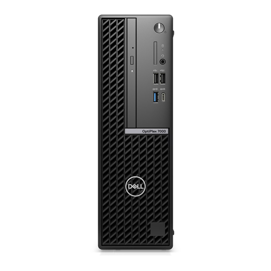
- Page 1 OptiPlex 7000 Small Form Factor Service Manual Regulatory Model: D17S Regulatory Type: D17S001 March 2022 Rev. A00...
- Page 2 A WARNING indicates a potential for property damage, personal injury, or death. © 2021-2022 Dell Inc. or its subsidiaries. All rights reserved. Dell, EMC, and other trademarks are trademarks of Dell Inc. or its subsidiaries. Other trademarks may be trademarks of their respective owners.
-
Page 3: Table Of Contents
Chapter 2: Removing and installing components................10 Recommended tools................................10 Screw list..................................... 10 Customer Replaceable Units (CRU) and Field Replaceable Units (FRU) list............11 Major components of OptiPlex 7000 Small Form Factor..................12 Side cover.................................... 14 Removing the side cover............................14 Installing the side cover.............................. 15 Front bezel...................................15... - Page 4 Installing the SD-card reader............................39 Coin-cell battery................................40 Removing the coin-cell battery..........................40 Installing the coin-cell battery...........................41 Power button..................................42 Removing the power button............................. 42 Installing the power button............................43 WLAN card..................................44 Removing the WLAN card............................44 Installing the WLAN card............................45 WLAN antenna................................... 47 Removing the internal WLAN antenna........................
- Page 5 Clearing CMOS settings..............................101 Clearing BIOS (System Setup) and System passwords..................101 Chapter 5: Troubleshooting....................... 102 Dell SupportAssist Pre-boot System Performance Check diagnostics.............. 102 Running the SupportAssist Pre-Boot System Performance Check.............. 102 Power-Supply Unit Built-in Self-Test ........................102 Diagnostic LED behavior..............................103 Recovering the operating system..........................104...
-
Page 6: Chapter 1: Working Inside Your Computer
You should only perform troubleshooting and repairs as authorized or directed by the Dell technical assistance team. Damage due to servicing that is not authorized by Dell is not covered by your warranty. See the safety instructions that is shipped with the product or at www.dell.com/regulatory_compliance. -
Page 7: Safety Precautions
ESD protection is an increasing concern. Due to the increased density of semiconductors used in recent Dell products, the sensitivity to static damage is now higher than in previous Dell products. For this reason, some previously approved methods of handling parts are no longer applicable. -
Page 8: Esd Field Service Kit
Always place parts in your hand, on the ESD mat, in the system, or inside an anti-static bag. ● Transporting Sensitive Components – When transporting ESD sensitive components such as replacement parts or parts to be returned to Dell, it is critical to place these parts in anti-static bags for safe transport. Working inside your computer... -
Page 9: Transporting Sensitive Components
It is recommended that all field service technicians use the traditional wired ESD grounding wrist strap and protective anti-static mat at all times when servicing Dell products. In addition, it is critical that technicians keep sensitive parts separate from all insulator parts while performing service and that they use anti-static bags for transporting sensitive components. -
Page 10: Chapter 2: Removing And Installing Components
Removing and installing components NOTE: The images in this document may differ from your computer depending on the configuration you ordered. Recommended tools The procedures in this document may require the following tools: ● Phillips screwdriver #0 ● Phillips screwdriver #1 ●... -
Page 11: Customer Replaceable Units (Cru) And Field Replaceable Units (Fru) List
Quantity Screw image System board #6-32 Customer Replaceable Units (CRU) and Field Replaceable Units (FRU) list Table 2. CRU/FRU list OptiPlex 7000 Small Form Factor CRU component FRU component Side cover Front bezel Intrusion switch 2.5-inch hard drive 3.5-inch hard drive... -
Page 12: Major Components Of Optiplex 7000 Small Form Factor
Coin-cell battery System fan Speaker VR heat-sink Power button Power supply unit Processor System board Major components of OptiPlex 7000 Small Form Factor The following image shows the major components of OptiPlex 7000 Small Form Factor. Removing and installing components... - Page 13 Removing and installing components...
-
Page 14: Side Cover
15. Optical drive 16. Processor NOTE: Dell provides a list of components and their part numbers for the original system configuration purchased. These parts are available according to warranty coverages purchased by the customer. Contact your Dell sales representative for purchase options. -
Page 15: Installing The Side Cover
Installing the side cover Prerequisites If you are replacing a component, remove the existing component before performing the installation procedure. About this task The following images indicates the location of the side cover and provide a visual representation of the installation procedure. Steps 1. -
Page 16: Installing The Front Bezel
Steps 1. Gently pry and release the front-bezel tabs sequentially from the top. 2. Rotate the front bezel outwards, away from the chassis, and remove the front bezel. Installing the front bezel Prerequisites If you are replacing a component, remove the existing component before performing the installation procedure. About this task The following images indicates the location of the front bezel and provide a visual representation of the installation procedure. -
Page 17: Intrusion Switch
Steps 1. Align and insert the front-bezel tabs with the slots on the chassis. 2. Rotate the front bezel towards the chassis and snap it into place. Next steps 1. Install the side cover. 2. Follow the procedure in after working inside your computer. -
Page 18: Installing The Intrusion Switch
Steps 1. Disconnect the intrusion-switch cable from the connector on the system board. 2. Slide the intrusion switch and lift it away from the computer. Installing the intrusion switch Prerequisites If you are replacing a component, remove the existing component before performing the installation procedure. About this task The following images indicate the location of the intrusion switch and provide a visual representation of the installation procedure. -
Page 19: Hard Drive
Steps 1. Slide the intrusion switch into the slot on the chassis. 2. Insert the connector from intrusion switch cable into the connector on the system board. Next steps 1. Install the side cover. 2. Follow the procedure in after working inside your computer. - Page 20 About this task The following images indicate the location of the 2.5-inch hard drive and provide a visual representation of the removal procedure. Removing and installing components...
-
Page 21: Installing The 2.5-Inch Hard Drive
Steps 1. Disconnect the hard-drive data and power cables from the connectors on the 2.5-inch hard drive. 2. Press the tab on the hard-drive carrier and lift the hard-drive carrier to release the hard-drive carrier from the chassis. NOTE: The hard-drive's power and data cables can only connected from the bottom side of the caddy. Make a note of the orientation of the hard drive to avoid errors during installation. - Page 22 Removing and installing components...
-
Page 23: Removing The 3.5-Inch Hard Drive
Steps 1. Align the slots on the 2.5-inch hard drive with the mounting points on the hard-drive carrier. 2. Pry the hard-drive carrier to align the mounting points on the hard-drive carrier with the slots on the 2.5-inch hard drive. 3. - Page 24 Steps 1. Disconnect the hard-drive data and power cables from the connectors on the 3.5-inch hard drive. 2. Press the tab on the hard-drive carrier and lift the hard-drive carrier. 3. Slide the hard-drive carrier away from the chassis and lift hard-drive carrier out of the disk-drive cage. 4.
-
Page 25: Installing The 3.5-Inch Hard Drive
Installing the 3.5-inch hard drive Prerequisites If you are replacing a component, remove the existing component before performing the installation procedure. About this task The following images indicate the location of the 3.5-inch hard drive and provide a visual representation of the installation procedure. -
Page 26: Hard-Drive And Optical-Drive Bracket
Steps 1. Align the mounting points on the carrier with the slots on the hard drive. 2. Snap the 3.5-inch hard-drive onto the hard-drive carrier. 3. Align the tabs on the hard-drive carrier with the slots on the chassis and snap the hard-drive carrier onto the disk-drive cage. -
Page 27: Installing The Hard-Drive And Optical-Drive Bracket
About this task The following images indicate the location of the hard-drive and optical-drive bracket and provide a visual representation of the removal procedure. Steps 1. Remove the hard-drive power and data cables that are routed via the locking mechanism. 2. - Page 28 About this task The following image indicates the location of the hard-drive and optical-drive bracket and provides a visual representation of the installation procedure. Steps 1. Connect the power and SATA cables to the optical drive while holding the bracket upside down. 2.
-
Page 29: Optical Drive
Optical drive Removing the optical drive Prerequisites 1. Follow the procedure in before working inside your computer. 2. Remove the side cover. 3. Remove the front bezel. 4. Remove the 2.5-inch hard-drive. 5. Remove the 3.5-inch hard-drive. 6. Remove the hard-drive and optical-drive bracket. - Page 30 Steps 1. Press the tab on the optical drive to release the optical drive from the hard-drive and optical drive bracket. Removing and installing components...
-
Page 31: Installing The Optical-Drive
2. Slide the optical drive out of the hard-drive and optical drive bracket. Installing the optical-drive Prerequisites If you are replacing a component, remove the existing component before performing the installation procedure. About this task The following images show the optical-drive and provide a visual representation of the installation procedure. Removing and installing components... - Page 32 Steps Slide the optical drive into the hard-drive and optical-drive bracket until it snaps into place. Removing and installing components...
-
Page 33: Solid-State Drive
Next steps 1. Install the hard-drive and optical-drive bracket. 2. Install the 3.5-inch hard-drive. 3. Install the 2.5-inch hard-drive. 4. Install the front bezel. 5. Install the side cover. 6. Follow the procedure in after working inside your computer. Solid-state drive Removing the M.2 2230 solid-state drive Prerequisites 1. -
Page 34: Installing The M.2 2230 Solid-State Drive
Installing the M.2 2230 solid-state drive Prerequisites If you are replacing a component, remove the existing component before performing the installation procedure. About this task The following images indicate the location of the M.2 2230 solid-state drive and provide a visual representation of the installation procedure. -
Page 35: Installing The M.2 2280 Solid-State Drive
3. Remove the front bezel. 4. Remove the 2.5-inch hard-drive. 5. Remove the 3.5-inch hard-drive. 6. Remove the hard-drive and optical-drive bracket. About this task The following images indicate the location of the M.2 2280 solid-state drive and provide a visual representation of the removal procedure. -
Page 36: Hard-Drive And Optical-Drive Supporting Bracket
Steps 1. Align the notch on the 2290 solid-state drive with the tab on the M.2 card slot on the system board. 2. Slide the 2280 solid-state drive into the M.2 card slot on the system board. 3. Replace the screw (M2x3) that secures the 2280 solid-state drive to the system board. Next steps 1. -
Page 37: Installing The Hard-Drive And Optical-Drive Supporting Bracket
6. Remove the hard-drive and optical-drive bracket. About this task The following images indicate the location of the hard-drive and optical-drive supporting bracket and provide a visual representation of the removal procedure. Steps 1. Remove the two (#6-32) screws that secures the bracket to the chassis. 2. -
Page 38: Sd-Card Reader
Steps 1. Align and place the bracket on the slot on the chassis. 2. Replace the two (#6-32) screws that secures the bracket to the chassis. Next steps 1. Install the hard-drive and optical-drive bracket. 2. Install the 3.5-inch hard-drive. 3. -
Page 39: Installing The Sd-Card Reader
About this task The following images indicate the location of the SD-card reader and provide a visual representation of the removal procedure. Steps 1. Remove the power-supply cables from the routing guides on the SD-card reader bracket. 2. Remove the two screws (M3x5) that secure the SD-card bracket to the system board and the chassis. 3. -
Page 40: Coin-Cell Battery
Steps 1. Place and align the screw holes on the SD-card reader to the screw holes on the chassis. 2. Connect the SD-card reader to the connector on the system board. 3. Replace the two screws (M3x5) that secure the SD-card bracket to the system board and the chassis. 4. -
Page 41: Installing The Coin-Cell Battery
Steps 1. Push the coin-cell battery-release lever on the coin-cell battery socket to release the coin-cell battery out of the socket. 2. Remove the coin-cell battery. Installing the coin-cell battery Prerequisites If you are replacing a component, remove the existing component before performing the installation procedure. About this task The following image indicates the location of the coin-cell battery and provides a visual representation of the installation procedure. -
Page 42: Power Button
Steps Insert the coin-cell battery into the socket with the positive side (+) label facing up and snap the battery in the socket. Next steps 1. Install the hard-drive and optical-drive bracket. 2. Install the 3.5-inch hard-drive. 3. Install the 2.5-inch hard-drive. -
Page 43: Installing The Power Button
Steps 1. Disconnect the power-button cable from the connector on the system board. 2. Press the release tabs on the power-button head and push the power button through the slot on the chassis. 3. Remove the power button and its cable from the from the slot on the chassis. Installing the power button Prerequisites If you are replacing a component, remove the existing component before performing the installation procedure. -
Page 44: Wlan Card
Steps 1. Insert the power button and its cable into the slot on the chassis. 2. Press the power button until it is seated on the slot on the chassis. 3. Connect the power-button cable to the connector on the system board. Next steps 1. -
Page 45: Installing The Wlan Card
6. Remove the hard-drive and optical-drive cage. About this task The following images indicate the location of the wireless card and provide a visual representation of the removal procedure. Steps 1. Remove the screw (M2x3) that secures the wireless card to the system board. 2. - Page 46 Steps 1. Connect the antenna cables to the WLAN card. The following table provides the antenna-cable color scheme for the WLAN card of your computer. Table 3. Antenna-cable color scheme Connectors on the wireless card Antenna-cable color Main (white triangle) White Auxiliary (black triangle) Black...
-
Page 47: Wlan Antenna
WLAN antenna Removing the internal WLAN antenna Prerequisites 1. Follow the procedure in before working inside your computer. 2. Remove the side cover. 3. Remove the front bezel. 4. Remove the 2.5-inch hard-drive. 5. Remove the 3.5-inch hard-drive. 6. Remove the hard-drive and optical-drive cage. -
Page 48: Wlan Antennas (External)
About this task The following image indicates the location of the WLAN antenna and provides a visual representation of the installation procedure. Steps 1. Route the WLAN antenna cables through the routing guides on the chassis. 2. Place and align the screw holes on the WLAN antenna with the screw holes on the chassis 3. - Page 49 5. Remove the 3.5-inch hard-drive. 6. Remove the hard-drive and optical-drive cage. 7. Remove the WLAN card. About this task The following images indicate the location of the external WLAN antennas and provide a visual representation of the removal procedure. Steps 1.
-
Page 50: Installing The External Wlan Antenna
Installing the external WLAN antenna Prerequisites If you are replacing a component, remove the existing component before performing the installation procedure. About this task The following images indicate the location of the WLAN antennas and provide a visual representation of the installation procedure. -
Page 51: Memory
7. Follow the procedure in after working inside your computer. Memory Removing the memory Prerequisites 1. Follow the procedure in before working inside your computer. 2. Remove the side cover. 3. Remove the 2.5-inch hard-drive. 4. Remove the 3.5-inch hard-drive. 5. -
Page 52: Processor Fan And Heat-Sink Assembly
About this task The following images indicate the location of the memory and provide a visual representation of the installation procedure. Steps 1. Ensure that the securing clips are in an open position. 2. Align the notch on the memory module with the tab on the memory-module slot. 3. -
Page 53: Installing The Processor Fan And Heat-Sink Assembly
NOTE: The heat sink may become hot during normal operation. Allow sufficient time for the heat sink to cool before you touch it. NOTE: For maximum cooling of the processor, do not touch the heat transfer areas on the heat sink. The oils in your skin can reduce the heat transfer capability of the thermal grease. -
Page 54: Voltage Regulator Heat Sink
Steps 1. Place the processor fan and heat-sink assembly on the system board and align the captive screws to the screw holes on the system board. 2. Tighten the four captive screws that secure the heat stink to the system board. 3. -
Page 55: Installing The Voltage-Regulator Heat Sink
CAUTION: For maximum cooling of the processor, do not touch the heat transfer areas on the heat sink. The oils in your skin can reduce the heat transfer capability of the thermal grease. 2. Remove the side cover. About this task The following image indicates the location of the voltage-regulator heat sink and provide a visual representation of the removal procedure. -
Page 56: Processor
Steps 1. Place the voltage-regulator heat sink on the system board. 2. Align the captive screws on the voltage-regulator heat sink to the screw holes on the system board. 3. Tighten the four captive screws that secure the voltage-regulator heat stink to the system board. Next steps 1. -
Page 57: Installing The Processor
Steps 1. Press the release lever down and then push it away from the processor to release it from the securing tab. 2. Extend the release lever completely and open the processor cover. CAUTION: When removing the processor, do not touch any of the pins inside the socket or allow any objects to fall on the pins in the socket. -
Page 58: Expansion Card
Steps 1. Ensure that the release lever on the processor socket is fully extended in the open position. 2. Align the notches on the processor with the tabs on the processor socket and place the processor in the processor socket. NOTE: Ensure that the processor-cover notch is positioned underneath the alignment post. -
Page 59: Installing The Graphics Card
Steps 1. Using the tab, lift and open the PCIe door. 2. Push and hold the securing tab on the graphics-card slot and lift the graphics card from the PCIe x16 card slot. 3. Lift the graphics card off the system board. Installing the graphics card Prerequisites If you are replacing a component, remove the existing component before performing the installation procedure. -
Page 60: Optional I/O Modules (Ps2/Serial)
Steps 1. Align the graphics card with the PCIe x16 card slot on the system board. 2. Using the alignment post on the PCIe slot, connect the card in the connector and press down firmly. Ensure that the card is firmly seated. - Page 61 3. Remove the front bezel. 4. Remove the heat-sink and fan assembly. About this task The following images indicate the location of the optional PS2 module and provides a visual representation of the removal procedure. Steps 1. Lift the pull tab and open the expansion-card door. Removing and installing components...
-
Page 62: Installing Optional Ps2 Module
2. Disconnect the PS2 module cable from the connector on the system board. 3. Remove the PS2 module from the computer. Installing optional PS2 module Prerequisites If you are replacing a component, remove the existing component before performing the installation procedure. About this task The following images indicate the location of the optional PS2 module and provide a visual representation of the installation procedure. - Page 63 Steps 1. Insert the optional PS2 module into its slot on the chassis. 2. Connect the PS2 cable to the connector on the system board. 3. Close the expansion-card door, and press until it clicks into place. Next steps 1. Install the heat-sink and fan assembly.
-
Page 64: Optional I/O Modules (Vga/Hdmi/Dp/Usb Type-C)
3. Follow the procedure in after working inside your computer. Optional I/O modules (VGA/HDMI/DP/USB Type-C) Removing optional I/O module Prerequisites 1. Follow the procedure in before working inside your computer. 2. Remove the side cover. 3. Remove the front bezel. 4. -
Page 65: Chassis Fan
About this task The following images indicate the location of the optional I/O module and provide a visual representation of the installation procedure. Steps 1. Using a screwdriver, remove the bracket covering the I/O module slot. NOTE: This step is only for systems that are being upgraded with the I/O module for the first time. 2. -
Page 66: Installing The Chassis Fan
2. Remove the side cover. 3. Remove the front bezel. 4. Remove the 2.5-inch hard-drive. 5. Remove the 3.5-inch hard-drive. 6. Remove the hard-drive and optical-drive bracket. About this task The following image indicates the location of the chassis fan and provide a visual representation of the removal procedure. Steps 1. -
Page 67: Speakers
Steps 1. Insert the rubber grommets on the chassis. 2. Align the slots on the fan with the rubber grommets on the chassis. 3. Route the rubber grommets through the slots on the fan and pull the rubber grommets until the fan snaps into position. 4. - Page 68 Steps 1. Disconnect the speaker cable from the connector on the system board. 2. Unroute the speaker cable from the routing guides on the chassis. 3. Press the tab and slide the speaker along with the cable from the slot on the chassis. Removing and installing components...
-
Page 69: Installing The Speaker
Installing the speaker Prerequisites If you are replacing a component, remove the existing component before performing the installation procedure. About this task The following image indicates the location of the speaker and provides a visual representation of the installation procedure. Steps 1. -
Page 70: Installing The Power-Supply Unit
About this task The following images indicate the location of the power-supply unit and provide a visual representation of the removal procedure. Steps 1. Disconnect the power-supply cables from the connectors on the system board. 2. Remove the power-supply cables from the routing guides on the chassis. 3. - Page 71 Steps 1. Place and align the screw holes on the power-supply unit to the screw holes on the chassis. 2. Replace the three (M6-32) screws to secure the power-supply unit to the chassis. 3. Route the power-supply cables through the routing guides on the chassis. 4.
-
Page 72: System Board
System board System board callouts - 7000 Small Form Factor The following image indicates the slots and connectors on your system board. 1. Intrusion switch cable 2. Processor-power cables 3. Processor fan connector 4. UDIMM slots From the left (a>b>c>d): DIMM 3 DIMM 1 DIMM 4... -
Page 73: Removing The System Board
19. M.2 2230/2280 solid-state drive slot 20. Processor socket 21. I/O cable Removing the system board Prerequisites 1. Follow the procedure in before working inside your computer. 2. Remove the side cover. 3. Remove the front bezel. 4. Remove the 2.5-inch hard-drive. - Page 74 Removing and installing components...
-
Page 75: Installing The System Board
Steps 1. Remove the screw (6-32) that secures the front I/O bracket to the chassis. 2. Rotate and remove the front I/O-bracket from the chassis 3. Disconnect all the cables that are connected to the system board. 4. Remove the four screws (#6-32) that secure the system board to the chassis. 5. - Page 76 Removing and installing components...
- Page 77 Removing and installing components...
- Page 78 Steps 1. Align and lower the system board into the system until the stand-off points at the back of the system board align with those on the chassis. 2. Replace the four (#6-32) screws to secure the system board to the chassis. 3.
-
Page 79: Chapter 3: Drivers And Downloads
Drivers and downloads When troubleshooting, downloading or installing drivers it is recommended that you read the Dell Knowledge Based article, Drivers and Downloads FAQ 000123347. Drivers and downloads... -
Page 80: Chapter 4: Bios Setup
BIOS setup CAUTION: Unless you are an expert computer user, do not change the settings in the BIOS Setup program. Certain changes can make your computer work incorrectly. NOTE: Depending on the computer and its installed devices, the items listed in this section may or may not be displayed. NOTE: Before you change BIOS Setup program, it is recommended that you write down the BIOS Setup program screen information for future reference. -
Page 81: System Setup Options
The one-time boot menu displays the devices that you can boot from including the diagnostic option. The boot menu options are: ● Removable Drive (if available) ● STXXXX Drive (if available) NOTE: XXX denotes the SATA drive number. ● Optical Drive (if available) ●... - Page 82 Table 5. System setup options—System information menu (continued) General-System Information Processor L2 Cache Displays the Processor L2 Cache size. Processor L3 Cache Displays the Processor L2 Cache size. HT Capable Displays whether the processor is HyperThreading (HT) capable. 64-Bit Technology Displays whether 64-bit technology is used.
- Page 83 Table 6. System setup options—System Configuration menu (continued) System Configuration Rear USB Configuration Enable or disable the rear USB ports. Audio Enable or disable the integrated audio controller. Miscellaneous Devices Enable or disable various onboard devices. Table 7. System setup options—Video menu Video Multi-Display Enable or disable multiple displays.
- Page 84 Table 9. System setup options—Secure Boot menu (continued) Secure Boot Expert Key Management Enable or disable Expert Key Management. Custom Mode Key Management Select the custom values for expert key management. Table 10. System setup options—Intel Software Guard Extensions menu Intel Software Guard Extensions Intel SGX Enable Enable or disable Intel Software Guard Extensions.
-
Page 85: Overview
SupportAssist System Resolution Auto OS Recovery Threshold Control the automatic boot flow for SupportAssist System Resolution Console and for Dell OS Recovery tool. Overview This section provides hardware specification for the system and contains no modifiable settings. Table 16. BIOS Overview Page... - Page 86 Table 16. BIOS Overview Page (continued) Options Description ● Signed Firmware Update - This helps to verify that only Dell Signed and released BIOS can be installed on the computer. Processor The Processor field provides information related to the CPU on the computer: ●...
-
Page 87: Boot Configuration
Table 16. BIOS Overview Page (continued) Options Description ● Bluetooth Device - This field mentions the type of Bluetooth device available for use on the computer. ● LOM MAC Address - This field provides the unique MAC address for the computer. Boot Configuration This section provides Boot Configuration related details and settings. -
Page 88: Integrated Devices
Integrated Devices This section provides Integrated Devices details and settings. Table 18. Integrated Devices Options Description Date/Time Date This section allows the user to change the date which takes effect immediately. The format used is MM/DD/YYYY. Time This section allows the user to change the time which takes effect immediately. -
Page 89: Storage
Table 18. Integrated Devices (continued) Options Description to clean or replace the dust filter based on the following time intervals: ● Disabled (selected by default) ● 15 days ● 30 days ● 60 days ● 90 days ● 120 days ●... -
Page 90: Display
Table 19. Storage (continued) Options Description ● Secure Digital (SD) Card (Enabled by default) ● Secure Digital (SD) Card Read-Only Mode Display This section provides display details and settings. Table 20. Display Options Description Multi-Display This section contains a toggle switch which allows the user to enable/disable Multi-Display. -
Page 91: Power
Table 21. Connection (continued) Options Description Wireless Radio Control This section contains a toggle switch that allows the user to enable or disable a feature where the system will sense a connection to a wired network and disable the WLAN or WWAN connection (OFF by default). -
Page 92: Security
Table 22. Power (continued) Options Description ● Disabled ● Enabled in S5 only ● Enabled in S4 and S5 (Selected by default) Intel Speed Shift Technology Intel Speed Shift Technology This section contains a toggle switch to allow the user to enable or disable Intel Speed Shift Technology support. -
Page 93: Passwords
Table 23. Security (continued) Options Description Chassis Intrusion This field controls the chassis intrusion feature ● Disabled - Will not report intrusions during POST ● Enabled - Will report intrusions during POST ● On-silent - Detects intrusions but does not display any detected intrusions during POST (Selected by default) Clear Intrusion Warning This section contains a toggle switch to enable/disable... -
Page 94: Update Recovery
Table 24. Passwords Options Description Admin Password This field allows the user to set, change, or delete the administrator password. System Password This field allows the user to set, change, or delete the system password. Internal HDD-0 Password This field allows the user to set, change, or delete the HDD-0's password. -
Page 95: System Management
OS recovery if the main operating system fails to boot with a set number of failures (ON by default). Dell Auto OS Recovery Threshold Dell Auto OS Recovery Threshold This field allows the user to select the number of failed boot attempts by the system before SupportAssist OS Recovery is triggered. -
Page 96: Keyboard
Table 26. System Management (continued) Options Description Wake on LAN Wake on LAN This field allows the user to select if and how the system should boot when connected to LAN. The options here are as follows: ● Disabled - The system will not boot with any special LAN signals (selected by default). -
Page 97: Performance
Table 28. Virtualization Options Description Intel Virtualization Technology Enable Intel Virtualization Technology(VT) This field contains a toggle switch to enable or disable Virtualization to run Virtual machine monitor(VMM) (enabled by default). VT for Direct I/O Enable Intel VT for Direct I/O This field allows the user to enable or disable the system from being able to perform VT for Direct I/O (enabled by default). -
Page 98: System Logs
Steps 1. Go to www.dell.com/support. 2. Click Product support. In the Search support box, enter the Service Tag of your computer, and then click Search. NOTE: If you do not have the Service Tag, use the SupportAssist feature to automatically identify your computer. You can also use the product ID or manually browse for your computer model. -
Page 99: Updating The Bios Using The Usb Drive In Windows
One-Time boot menu on the computer. Most of the Dell computers built after 2012 have this capability, and you can confirm by booting your computer to the F12 One-Time Boot Menu to see if BIOS FLASH UPDATE is listed as a boot option for your computer. If the option is listed, then the BIOS supports this BIOS update option. -
Page 100: System And Setup Password
Steps 1. From a turn off state, insert the USB drive where you copied the flash into a USB port of the computer. 2. Turn on the computer and press F12 to access the One-Time Boot Menu, select BIOS Update using the mouse or arrow keys then press Enter. -
Page 101: Deleting Or Changing An Existing System Setup Password
Clearing BIOS (System Setup) and System passwords About this task To clear the system or BIOS passwords, contact Dell technical support as described at www.dell.com/contactdell. NOTE: For information on how to reset Windows or application passwords, refer to the documentation accompanying Windows or your application. -
Page 102: Chapter 5: Troubleshooting
Check diagnostics About this task SupportAssist diagnostics (also known as system diagnostics) performs a complete check of your hardware. The Dell SupportAssist Pre-boot System Performance Check diagnostics is embedded with the BIOS and is launched by the BIOS internally. The embedded system diagnostics provides a set of options for particular devices or device groups allowing you to: ●... -
Page 103: Diagnostic Led Behavior
Blinking pattern Amber White Problem description Suggested resolution Unrecoverable SPI Flash Failure CPU failure ● Run the Dell Support Assist/Dell Diagnostics tool. ● If problem persists, replace the system board. System board failure (included ● Flash latest BIOS version BIOS corruption or ROM ●... -
Page 104: Recovering The Operating System
It enables you to diagnose hardware issues, repair your computer, back up your files, or restore your computer to its factory state. You can also download it from the Dell Support website to troubleshoot and fix your computer when it fails to boot into their primary operating system due to software or hardware failures. -
Page 105: Backup Media And Recovery Options
Backup media and recovery options It is recommended to create a recovery drive to troubleshoot and fix problems that may occur with Windows. Dell proposes multiple options for recovering Windows operating system on your Dell PC. For more information. see... -
Page 106: Chapter 6: Getting Help And Contacting Dell
Getting help and contacting Dell Self-help resources You can get information and help on Dell products and services using these self-help resources: Table 33. Self-help resources Self-help resources Resource location Information about Dell products and services www.dell.com My Dell app...