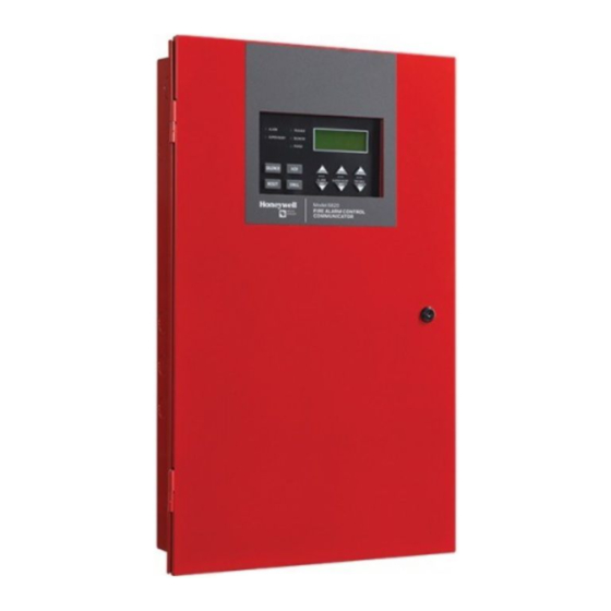
Honeywell 6820 Manual
Addressable fire alarm conrol panel
Hide thumbs
Also See for 6820:
- Installation and optimization manual (250 pages) ,
- Installation and operation manual (216 pages)

Related Manuals for Honeywell 6820


Summary of Contents for Honeywell 6820
- Page 1 6820/6820EVS Addressable Fire Alarm Conrol Panel Manual Document LS10144-001SK-E Rev: E 4/6/2022 ECN: 151062...
- Page 2 Adequate written records of all rise feature of each detector should be tested at least once per year inspections should be kept. by a qualified fire protection specialist. Heat detectors are designed to Limit-F-2020 protect property, not life. 6820/EVS Manual — P/N LS10144-001SK-E:E 4/6/2022...
- Page 3 Flexput®, Honeywell®, JumpStart®, Silent Knight®, and SWIFT® are registered trademarks of Honeywell International Inc.Microsoft® and Windows® are registered trademarks of the Microsoft Corporation. Chrome™ and Google™ are trademarks of Google Inc. Firefox® is a registered trademark of The Mozilla Foundation.
- Page 4 Electrical and electronic equipment contains materials, parts and substances, which can be dangerous to the environment and harmful to human health if the waste of electrical and electronic equipment (WEEE) is not disposed of correctly. 6820/EVS Manual — P/N LS10144-001SK-E:E 4/6/2022...
-
Page 5: Table Of Contents
3.5.4: Maximum Battery Standby Load................................25 Section 4: Control Panel Installation ..........................26 4.1: Mounting the Control Panel Cabinet ................................26 4.1.1: Preventing Water Damage..................................26 4.1.2: Removing the 6820 Assembly from the Housing..........................26 4.1.3: Ethernet Connection .....................................26 4.2: Board Assembly Diagram....................................27 4.3: Wiring Specifications.......................................28 4.4: AC Power Connection .....................................29... - Page 6 Section 7: Programming Overview ..........................74 7.1: JumpStart Auto-Programming ..................................74 7.1.1: Input Points......................................74 7.1.2: Output Points ......................................74 7.1.3: Running JumpStart Auto-Programming ...............................74 7.2: Mapping Overview ......................................75 7.2.1: Input Point Mapping .....................................76 7.2.2: Output Circuit Mapping..................................76 6820/EVS Manual — P/N LS10144-001SK-E:E 4/6/2022...
- Page 7 9.3.7: Conduct a Communicator Test ................................115 9.3.8: Manual AlarmNet Registration................................115 9.3.9: Silence Alarms or Troubles ................................115 9.3.10: Reset Alarms.....................................116 9.3.11: Check Detector Sensitivity Through Point Status ...........................116 9.3.12: View Status of a Point ..................................118 6820/EVS Manual — P/N LS10144-001SK-E:E 4/6/2022...
- Page 8 10.8.4: Using HFSS Voice Message Load Software ............................136 Section 11: Reporting ..............................138 11.1: Receivers Compatible with the Control Panel .............................138 11.2: SIA - Panel PI Modifier Reporting ................................147 11.3: SIA – Panel Communicator ..................................148 6820/EVS Manual — P/N LS10144-001SK-E:E 4/6/2022...
- Page 9 A.2: Example Name Edit ......................................157 Appendix B: Expanded Receiver/Panel Relationship ....................158 Appendix C: Cadence Patterns ............................ 159 Appendix D: Panel Security............................160 Model 6820 Basic Operating Instructions ........................161 Model 6820EVS Basic Operating Instructions......................163 Keypad and LED Indicators............................165 EVS Control..................................167...
-
Page 10: Section 1: Introduction
1.1.1 Hardware Features • The basic 6820 panel contains one built-in signaling line circuit (SLC), which supports up to 159 SK sensors and 159 SK modules or 127 SD SLC devices. Additional SLC loops can be added to increase overall point capacity. -
Page 11: 4: 6820Evs Features
The term module is used for all hardware devices except for SLC addressable devices and notification appliances. This includes the 6820 panel itself and the built-in power supply. It also refers to any (optional) 5815XL or 6815 SLC expansion modules. -
Page 12: Compatible Products
WSKHEAT-ROR Wireless Heat Rate of Rise Heat Detector with 4” base WSK-HEAT Wireless 135° fixed Heat Detector with 4” base WSK-MONITOR Wireless Addressable Monitor module WSK-RELAY Wireless Addressable Relay module Table 1.1 Compatible Products 6820/EVS Manual — P/N LS10144-001SK-E:E 4/6/2022... -
Page 13: Related Documentation
Type of Device Model Description Miscellaneous 7860 Telephone Cord RJ31X cord for connecting phone line to the 6820 HFSS Honeywell Fire For communication and panel programming with a Windows-based computer. Software Suite Enables remote viewing of detector status and event history. -
Page 14: Section 2: Agency Listings, Approvals, And Requirements
Since the 6820 is a commercial fire alarm panel, it must be connected upstream of all other equipment utilizing the phone lines. If you have questions about the installation, contact your telephone company or a qualified installer. -
Page 15: Underwriters Laboratories (Ul)
Use both phone lines. Enable phone line monitors for both lines. You must program a phone number and a test time so that the 6820 shall automatically initiate and complete a test signal transmission sequence to its associated receiver at least once every 6 hours, using two phones or one phone line with Ethernet/cellular backup. -
Page 16: 7: Nfpa Requirements
5220 Rev Polarity Module Keltron 3158 Rev Polarity Module CELL-MOD, CELL-CAB-SK Transmitter HWF2A-COM, HWF2V-COM Transmitter Y = YES, N = NO, O = OPTIONAL Table 2.1 NFPA Requirements for 6820 Central Remote Mass Notification Model/Module Description Local Auxiliary EVAC Station... -
Page 17: Section 3: Before You Begin Installation
6820 panel for the first time. 3.1 Inventory When the 6820 shipment is received, check that all the parts have been included in the shipment. The shipment consist of one of each of the following: •... -
Page 18: Calculating Current Draw And Standby Battery
The following steps must be taken when determining 6820 current draw and standby battery requirements. For the 6820, the worst case current draw is listed for the panel, addressable devices, and SLC expanders. Fill in the number of addressable devices and expanders that will be used in the system and compute the current draw requirements for alarm and standby. -
Page 19: 2: Current Draw Worksheet For Sk Slc Devices
Make sure that the total alarm current you calculated, including current for the panel itself, does not exceed 9.0 A. This is the maximum alarm current for the 6820 control panel. If the current is above 9.0 A you will need to use a notification power expander(s) such as the 5496 or the 5895XL intelligent power expander, to distribute the power loads so that the 6820 or the power expanders do not exceed their power ratings. - Page 20 15 mA Accessories Modules 6815 SLC Loop Expander Standby: 78 mA Alarm: 78 mA 6860 Remote LCD Annunciator Standby: 27 mA Alarm: 53 mA Table 3.2 Current Draw Worksheet for SK SLC Devices (Continued) 6820/EVS Manual — P/N LS10144-001SK-E:E 4/6/2022...
- Page 21 Refer to devices manual for current rating IPDACT-2 IP Communicator Standby: 93 mA Alarm: 136 mA IPDACT-2UD IP Communicator Standby: 98 mA Alarm: 155 mA Table 3.2 Current Draw Worksheet for SK SLC Devices (Continued) 6820/EVS Manual — P/N LS10144-001SK-E:E 4/6/2022...
-
Page 22: 3: Current Draw Worksheet For Sd Slc Devices
Current per number of devices. Standby 190 mA 190 mA Fire Panel (Current draw from battery) Alarm: 250 mA SD500-AIM SD500-MIM SD500-PS Standby/Alarm: 0.55 mA SD500-ARM SD505-HEAT SD505-PHOTO Table 3.3 Current Calculation Worksheet for SD Devices 6820/EVS Manual — P/N LS10144-001SK-E:E 4/6/2022... - Page 23 10 mA with/without EVS-CE4 EVS-INT50W Internal Amplifier Standby: 52 mA Alarm @ 25V: 275 mA Alarm @ 70V: 310 mA EVS-100W Amplifier Standby/Alarm (SBUS): 10 mA Table 3.3 Current Calculation Worksheet for SD Devices (Continued) 6820/EVS Manual — P/N LS10144-001SK-E:E 4/6/2022...
- Page 24 Alarm sounding period in hours. (For example, 5 minutes = 0.0833 hours) Multiply lines E and H. Total alarm AH Add lines G and I. Multiply by the Derating Factor 1.25 Total ampere hours required Table 3.3 Current Calculation Worksheet for SD Devices (Continued) 6820/EVS Manual — P/N LS10144-001SK-E:E 4/6/2022...
-
Page 25: 4: Maximum Battery Standby Load
3.5.4 Maximum Battery Standby Load Tables 3.4 and 3.5 show the standby load calculations for the 6820 based on 24 and 90 hours of standby. The standby load calculations of line D in the Current Draw Calculation Worksheet must be less than the number shown in Tables 3.4 and 3.5 for the selected battery size, standby hour and alarm time. -
Page 26: Section 4: Control Panel Installation
The 6820 cabinet can be surface or flush mounted. Cabinet base dimensions are 24.75” H x 14.5" W. If you flush mount there should be 1.5" to 1.75" of cabinet extruding from the wall, this should be measured from either the top edge or bottom edge to the exterior side of the sheet rock. -
Page 27: Board Assembly Diagram
If you should need to remove the board assembly for repair, remove the four mounting nuts which hold the assembly in the cabinet. Then, lift the entire assembly out of the cabinet. Do not attempt to remove the circuit boards from the metal bracket. 6820/EVS Manual — P/N LS10144-001SK-E:E 4/6/2022... -
Page 28: Wiring Specifications
SBUS phone lines 0.25” spacing must be battery battery maintained between each of these circuit types, as well as between power-limited and non- power-limited circuits. Figure 4.3 Wire Routing Example for 6820 6820/EVS Manual — P/N LS10144-001SK-E:E 4/6/2022... -
Page 29: Ac Power Connection
BATTERY CONTAINS SULFURIC ACID WHICH CAN CAUSE SEVERE BURNS TO THE SKIN AND EYES AND CAN DESTROY FABRICS. IF CONTACT IS MADE WITH SULFURIC ACID, IMMEDIATELY FLUSH THE SKIN OR EYES WITH WATER FOR 15 MINUTES AND SEEK IMMEDIATE MEDICAL ATTENTION 6820/EVS Manual — P/N LS10144-001SK-E:E 4/6/2022... -
Page 30: 1: Battery Accessory Cabinets
• If using the battery cable extenders provided (P/N 140643), mount the RBB cabinet no more than 18" away from the main control panel cabinet. This will ensure that the battery cables reach the battery terminals. cabinet mounting holes Figure 4.7 RBB Cabinet Mounting Holes 6820/EVS Manual — P/N LS10144-001SK-E:E 4/6/2022... -
Page 31: Sbus Wiring
Figure 4.10 Cover Plate Mounting Keyholes and Cover Mounting Screws Alignment 4.6 SBUS Wiring This section contains information on calculating SBUS wire distances and the types of wiring configurations (Class A and B). 6820/EVS Manual — P/N LS10144-001SK-E:E 4/6/2022... -
Page 32: 1: Calculating Wiring Distance For Sbus Modules
586 ft. 933 ft. 1476 ft. 0.900 206 ft. 521 ft. 829 ft. 1312 ft. 1.000 (Max) 185 ft. 469 ft. 746 ft. 1181 ft. Table 4.2 Wire Distances Per Wire Gauge Using Copper Wire 6820/EVS Manual — P/N LS10144-001SK-E:E 4/6/2022... -
Page 33: 2: Wiring Configurations
For proper system supervision do not use looped supervised, power-limited wire under terminals marked A, B, +, and - of the SBUS device connectors. Break wire runs to provide supervision of connections. EXT. COMM Figure 4.11 SBUS Class A Wiring 6820/EVS Manual — P/N LS10144-001SK-E:E 4/6/2022... -
Page 34: 6855 Remote Annunciator Installation
(see Section 7.1). You can also add it manually (see Section 8.2.2). Select a name, if desired. 4.7.1 Mounting the 6855 This section of the manual describes mounting the remote annunciator. The annunciator can be flush- or surface-mounted. 6820/EVS Manual — P/N LS10144-001SK-E:E 4/6/2022... - Page 35 Place backbox over the top screw, level and secure. Mark and drill the left and right upper and lower mounting holes. Install remaining fasteners and tighten. Run wires to the control panel. Refer to Figure 4.17. 6820/EVS Manual — P/N LS10144-001SK-E:E 4/6/2022...
-
Page 36: 2: 6855 Connection To The Panel
Attach the door assembly to the backbox using the screws provided. Refer to Figure 4.15. 4.7.2 6855 Connection to the Panel Connect the 6855 to the panel as shown below. supervised, power-limited FACP 6855 annunciator EXT. COMM Figure 4.17 6855 Connection to the Panel 6820/EVS Manual — P/N LS10144-001SK-E:E 4/6/2022... -
Page 37: 5860 Remote Annunciator Installation
5860 Remote Annunciator Installation Control Panel Installation 4.8 5860 Remote Annunciator Installation The 5860 is an optional remote annunciator. Up to 16 annunciators can be added to the 6820 system. FIRE ALARM ANNUNCIATOR Figure 4.18 5860 Remote Annunciator 5860 installation involves the following steps: Ensure the power is off at the panel. - Page 38 Drill holes in the surface to match the screw holes on the backbox. Refer to Figure 4.20 for locations. Fit the trim ring over the backbox. Attach the backbox to the wall using screws provided. 6820/EVS Manual — P/N LS10144-001SK-E:E 4/6/2022...
-
Page 39: 6860 Remote Annunciator Installation
Use the DIP switches on the back of the 6860 to assign an SBUS ID# (see Section 4.15.1). The 6860 module must be added to the system through programming. JumpStart Auto-Programming will add the module automatically (see Section 8.6.7). 6820/EVS Manual — P/N LS10144-001SK-E:E 4/6/2022... -
Page 40: 1: Mounting The 6860
Place backbox over the top screw, level and secure. Mark and drill the left and right upper and lower mounting holes. Install remaining fasteners and tighten. Run wires to the control panel. Refer to Figure 4.27. 6820/EVS Manual — P/N LS10144-001SK-E:E 4/6/2022... -
Page 41: 2: 6860 Connection To The Panel
Make sure power is off at the panel. Mount the 5815XL in the 6820 cabinet, the 5895XL cabinet, or the 5815RMK remote mounting kit. Use the standoffs located under the control panel board assembly and secure with screws provided with the 5815XL. For additional information, see the 5895XL Installation Manual or the 5815RMK Installation Instructions. -
Page 42: 1: 5815Xl Connection To The Panel
Make sure power is off at the panel. Mount the 6815 in the 6820 cabinet, the 5895XL cabinet, or the 5815RMK remote mounting kit. Use the standoffs located under the control panel board assembly and secure with screws provided with the 6815. For additional information see the 5895XL Installation Manual . -
Page 43: 1: 6815 Connection To The Panel
Connect the 5824 to the FACP as shown in Figure 4.32. NOTE: There is a maximum of four 5824 modules allowed per panel. Use the DIP switches on the 5824 board to assign an SBUS ID# to the 5824 (see Section 4.15.1). 6820/EVS Manual — P/N LS10144-001SK-E:E 4/6/2022... -
Page 44: 1: Selecting 5824 Options
When used with the 6820EVS, the 5880 inputs can be programmed to replicate the eight EVS buttons located on the front of the voice control module. A maximum of eight 5880 modules can be used in the system. The following sub-sections describe hardware installation. Refer to Section 8 for programming information. 6820/EVS Manual — P/N LS10144-001SK-E:E 4/6/2022... -
Page 45: 1: 5880 Board Layout
EXT. COMM Figure 4.35 5880 Connection to 6820 4.13.3 LED Wiring There are four 12-pin connectors on the 5880 board for connecting LEDs. Each LED gets its power from Pin 11. Internal resistors are sized so that there is approximately 10 mA of current for each LED; no series resistors are required. LED outputs can be mapped to output circuits. -
Page 46: 4: Dry Contact Wiring
IN - 48 IN - 47 IN - 46 IN - 45 IN - 44 C+ IN - 43 IN - 42 IN - 41 5880 Figure 4.37 Dry Contact Wiring 6820/EVS Manual — P/N LS10144-001SK-E:E 4/6/2022... -
Page 47: 5865-3 / 5865-4 Led Annunciator Installation
The 5865 connects to the panel via the SBUS. Make connections as shown below. After the 5865 is connected to the panel, it must be added to the system. This programming step is described in Section 8.2.2. FACP 5865 supervised, power-limited Class B EXT. COMM Figure 4.39 5865 Connection to the FACP 6820/EVS Manual — P/N LS10144-001SK-E:E 4/6/2022... -
Page 48: 2: 5865 Mounting
Table 4.1 for a list of compatible devices), you must use the DIP switches on the module to assign an ID number to the module. Address zero is an invalid address and is not allowed. 6820/EVS Manual — P/N LS10144-001SK-E:E 4/6/2022... -
Page 49: 2: Sbus Bandwidth Considerations
DATA VOICE RING1 TIP1 RING1 TIP1 RING2 TIP2 RING2 TIP2 OUT- OUT+ EXT. COMM NETWORK NETWORK BATTERY SLC PGM TELCO PHONE TELCO PHONE supervised Model Model #7860 #7860 Figure 4.43 Connection of Telephone Lines 6820/EVS Manual — P/N LS10144-001SK-E:E 4/6/2022... -
Page 50: Flexput I/O Circuits
Wire the Class A notification appliances as shown in Figure 4.45. CAUTION: SYSTEM SUPERVISION FOR PROPER SYSTEM SUPERVISION DO NOT USE LOOPED WIRE UNDER TERMINALS MARKED – AND + OF THE NAC CIRCUIT. BREAK WIRE RUNS TO PROVIDE SUPERVISION OF CONNECTIONS. 6820/EVS Manual — P/N LS10144-001SK-E:E 4/6/2022... -
Page 51: 2: Conventional Input Switch Circuits
To install a Class B switch, do the following. Wire the Class B switch as shown in Figure 4.46. Configure the circuit through programming (see Section 8.5). EOL 4.7 kΩ supervised, power-limited Figure 4.46 Class B Input Switches 6820/EVS Manual — P/N LS10144-001SK-E:E 4/6/2022... -
Page 52: 3: Installing 2-Wire Smoke Detectors
To install a Class B two-wire smoke detector, wire as shown in Figure 4.48. supervised, power limited Flexput Circuit 6 is used as an example. Either Flexput circuit can be used. EOL 4.7 kΩ Figure 4.48 Two-Wire Class B Smoke Detector 6820/EVS Manual — P/N LS10144-001SK-E:E 4/6/2022... -
Page 53: 4: Installing 4-Wire Smoke Detectors
Figure 4.51 illustrates how to install a 4-wire Class A detector. Conventions used for wiring 4-wire Class A loops: One Class A 4-wire loop can be connected to the control panel. The wiring class of the external power source must match the wiring class of the device being powered. 6820/EVS Manual — P/N LS10144-001SK-E:E 4/6/2022... -
Page 54: 5: Auxiliary Power Installation
30 seconds, then re-applied. Refer to the Device Compatibility Document for compatible four wire smoke detectors. Sounder Sync Power Sounder Sync Power continuously outputs the System Sensor synchronization pattern and is intended for use with B200S sounder bases. 6820/EVS Manual — P/N LS10144-001SK-E:E 4/6/2022... -
Page 55: Onboard Relays (Conventional)
Wire the 3158 to the control panel as shown in the connection list. Wire the 3158 within 20 feet of the control panel. Wiring must be enclosed in conduit. Program control panel Relay 1 for alarm. Program Flexput circuit 5 for alarm. 6820/EVS Manual — P/N LS10144-001SK-E:E 4/6/2022... -
Page 56: 2: City Box Connection Using The 5220 Module
Wire the 5220 to the control panel as shown in Figure 4.55. This drawing also shows how to connect the city box coil to terminals 3 and 4 on the 5220. Do not install an EOL resistor in the terminals of the Flexput circuit used for this application. Connect earth ground wire to the 5220 chassis with mounting screw. 6820/EVS Manual — P/N LS10144-001SK-E:E 4/6/2022... -
Page 57: 3: Using The Addressable Relay Module For City Box Connection
SK-RELAY to SLC (-) (+) to SBUS out (+) to SBUS out (-) UL listed EOL must be Installed in City Box Enclosure to city box Figure 4.56 Relay Module for City Box Connection 6820/EVS Manual — P/N LS10144-001SK-E:E 4/6/2022... -
Page 58: 4: Nfpa 72 Polarity Reversal
Wire the 7644-L8 to the control panel as shown in Figure 4.59. Do not install an EOL resistor on the terminals of the circuit used. NOTE: Use only Flexput/NAC circuits on the control panel for reverse polarity. Program the circuit as a notification circuit. See Section 8.5.3. 6820/EVS Manual — P/N LS10144-001SK-E:E 4/6/2022... - Page 59 O I/06 X O I/08 X remote indicator black white 7644-L8 7644-L8 Figure 4.58 Polarity Reversal Connection Using the 7644-L8 7644-L8 black white 7644-L8 remote indicator Figure 4.59 Polarity Reversal Connection Using the 7644-L8 6820/EVS Manual — P/N LS10144-001SK-E:E 4/6/2022...
-
Page 60: 5: Transmitter Activated By Dry Contacts
4.19.5 Transmitter Activated by Dry Contacts This section describes the connection of a UL 864 listed remote station transmitter to the 6820 dry relay contacts. The 6820 FACP contacts must be supervised by the remote station transmitter module using end-of-line resistors (ELRs) with a value determined by the transmitter manufacturer. -
Page 61: Section 5: Common Communications Link
All methods of panel connectivity can be used within the same linked system. 5.2 SK-NIC Connection Options When linking a group of 6820 panels, you must use the SK-NIC to link the panels together. See Figure 5.1 and Figure 5.2, for internal mounting or external mounting of SK-NIC option. -
Page 62: Nic Wiring Options
SK-NIC Wiring Options 5.3 SK-NIC Wiring Options Linking a group of 6820 panels requires the use of a network interface card with each panel. The SK-NIC connects to other linked units using unshielded, twisted-pair wiring or fiber optic cable. Figure 5.3 SK-NIC Network Interface Card 5.3.1 Fiber Loop Modules... -
Page 63: 2: Sk-Nic Installation
A combination of both medium types can be used. See Figure 5.7, Figure 5.8, Figure 5.9, and Figure 5.10 for SK-NIC wiring examples. 5.3.3 SK-NIC Remote Mounting Follow the steps above except, the 6-pin cable that runs from the SK-NIC to the 6820 must be run in conduit. Refer to Figure 5.1. 6820/EVS Manual — P/N LS10144-001SK-E:E 4/6/2022... -
Page 64: 4: Wiring
Fiber optic cable between multiple panels is shown in Figure 5.8 and Figure 5.9. Class X is shown with a dotted line. port 2 last control panel/SK-NIC Class X wiring port 1 port 2 next control panel/SK-NIC port 1 port 2 first control panel/SK-NIC port 1 Figure 5.8 Fiber-Optic Wiring Multi-Mode Example 6820/EVS Manual — P/N LS10144-001SK-E:E 4/6/2022... - Page 65 A mixture of fiber optic cable and twisted pair wiring between multiple panels is shown in Figure 5.10. Class X cabling is shown with dotted line. port 2 last control panel/SK-NIC Class X wiring port 1 port 2 next control panel/SK-NIC port 1 port 2 first control panel/SK-NIC port 1 Figure 5.10 Twisted-Pair and Fiber-Optic Combination Wiring Example 6820/EVS Manual — P/N LS10144-001SK-E:E 4/6/2022...
-
Page 66: Setting The Id For Each Panel
See the figure below for possible DIP switch settings. Address 0 is an invalid address and cannot be used. Address Address Address Address 4 5 6 4 5 6 4 5 6 4 5 6 Figure 5.11 PanelID Settings 6820/EVS Manual — P/N LS10144-001SK-E:E 4/6/2022... -
Page 67: Section 6: Network Management
Section 6: Network Management NOTE: Although the word “Network” is used in this section, it applies to system menus that relate to the physical wire and/or fiber optic connections between multiple panels. The 6820 does not support peer-to-peer networking. 6.1 Network Diagnostics 6.1.1 Ping Panel... -
Page 68: 4: Computer Access
Each panel on the 6820 communication link specifies which communicator is used for reporting. The communication link capability of the 6820 system allows all panels to use the same communicator providing an economical solution for reducing the number of paths required for reporting purposes. -
Page 69: Voice Options
Receiver Configuration The 6820 network can report events to as many as 68 receivers. See Appendix B for panel/receiver relationship numbers. Each receiver can be a phone number and reporting format. Phone numbers can be up to forty digits long. -
Page 70: 2: Edit Voice Commands
• Custom Emergency Comm • Emergency Supervisory • CO Alarm • CO Supervisory Select whether a Message or Tone Only should be played. If Message is selected, choose the desired message for the command. 6820/EVS Manual — P/N LS10144-001SK-E:E 4/6/2022... -
Page 71: Sync Network Options
Line #1 scrolls to show the date. Scroll down to see checksum. Figure 6.2 Sync Network Options NOTE: If you try to sync with the network and an incompatible panel is found, an error message will display. 6820/EVS Manual — P/N LS10144-001SK-E:E 4/6/2022... -
Page 72: Network Management Quick Reference
Report Troubles Report Events by Point Communicator Report Table Primary Receiver See, "Communicator Reporting Table". Primary Account Test Primary Account Secondary Receiver Secondary Account Test Secondary Account Table 6.2 Network Management Quick Reference Chart 6820/EVS Manual — P/N LS10144-001SK-E:E 4/6/2022... - Page 73 Fire Interlock Release Fire Interlock Alert Emergency Edit Voice Supervisory Choose Site See Section 6.3.2 Commands CO Alarm CO Supervisory Sync Network See Section 6.4 Options Table 6.2 Network Management Quick Reference Chart (Continued) 6820/EVS Manual — P/N LS10144-001SK-E:E 4/6/2022...
-
Page 74: Section 7: Programming Overview
The first JumpStart AutoProgramming creates one zone (Zone 1) and assigns all input points to Zone 1. Zone 1 is mapped to Output Group 1. 7.1.2 Output Points The 6820 JumpStart creates three output groups. The 6820EVS with amplifiers will create four output groups. The output circuits are assigned as follows: Configured as Notification and assigned to Group 1. -
Page 75: Mapping Overview
& special optional system events Figure 7.1 Mapping Overview NOTE: Mapping cannot be programmed through the annunciators. It can only be programmed through the HFSS Honeywell Fire Software Suite. 6820/EVS Manual — P/N LS10144-001SK-E:E 4/6/2022... -
Page 76: 1: Input Point Mapping
5 Relay 1 group 998 JumpStart creates group 998 and output circuit 6 group 999 for Relay 1 and Relay 2. group 999 Relay 2 Figure 7.3 Assigning Output Circuits to Groups (Example) 6820/EVS Manual — P/N LS10144-001SK-E:E 4/6/2022... -
Page 77: 3: Event Mapping
This example shows Zone 1 manual pull alarm event mapped to: • Group 1 using constant output. through • Group 5 using ANSI 3.41 output pattern. group 250 Figure 7.4 Example of Zone Events Mapped to Output Groups and Patterns 6820/EVS Manual — P/N LS10144-001SK-E:E 4/6/2022... -
Page 78: 4: Mapping Led Points
Mapping. When using HFSS, you can set up the programming options for the panel, save the options in a file, then download the file to the panel. You can connect to the control panel directly using the onboard USB or Ethernet. Updates are available at www.silentknight.com. 6820/EVS Manual — P/N LS10144-001SK-E:E 4/6/2022... -
Page 79: Programming Using An Annunciator
Select from a scrolling list Use up arrow and down arrow to move through a list of available options. When the option you want to select is displayed, press ENTER. Table 7.1 Menu Options 6820/EVS Manual — P/N LS10144-001SK-E:E 4/6/2022... -
Page 80: Programming Menu Quick Reference
EVS-VCM Voice Control Module EVSRVM Remote Voice Module SKNIC Network Interface Card Delete Module Select Module See Section 8.2.3 View Module List Select Module See Section 8.2.4 Table 7.2 Programming Menu Quick Reference Chart 6820/EVS Manual — P/N LS10144-001SK-E:E 4/6/2022... - Page 81 Cadence View Group Select Group See Section 8.4.2 Points Edit OPG Select template Modify name and which output groups are in template See Section 8.4.3 Template Table 7.2 Programming Menu Quick Reference Chart (Continued) 6820/EVS Manual — P/N LS10144-001SK-E:E 4/6/2022...
- Page 82 ECS INPUT LATCH NON-LATCH ECS TAMPER LATCH NON-LATCH ECS SUPER- LATCH VISORY NON-LATCH TROUBLE_MON NOTIF OUTPUT PT Select Group 2,3,4,5 AUX CONST AUX RESET AUX DOOR Table 7.2 Programming Menu Quick Reference Chart (Continued) 6820/EVS Manual — P/N LS10144-001SK-E:E 4/6/2022...
- Page 83 RLY BAS Silence or Non-Silence I-SdrBa Latch or non-latch, (Intelligent Single station or Multi station, Silence or Non- Sounder Base) Silence, volume high (default) or low Table 7.2 Programming Menu Quick Reference Chart (Continued) 6820/EVS Manual — P/N LS10144-001SK-E:E 4/6/2022...
- Page 84 Single station or Multi Sounder Base) station, Silence or Non- Silence, volume high (default) or low BEAM SUP DET Same function LATCH 2,3,,4,5 as DETECTOR NON-LATCH Table 7.2 Programming Menu Quick Reference Chart (Continued) 6820/EVS Manual — P/N LS10144-001SK-E:E 4/6/2022...
- Page 85 Silence, volume high (default) or low 2,4,6 Photo See Section 8.5 W-Detector 2,4,6 2,4,6 Acclimate 2,4,6 Photo-Heat 2,4,6 Heat W-SUP DET Same as W- 2,4,6 Detector Table 7.2 Programming Menu Quick Reference Chart (Continued) 6820/EVS Manual — P/N LS10144-001SK-E:E 4/6/2022...
- Page 86 CO 4 WIRE Latch SUP DET Non-Latch Select Group or Zone Number Group or Zone selection will appear depending on the function selected Edit Name Enter Name Table 7.2 Programming Menu Quick Reference Chart (Continued) 6820/EVS Manual — P/N LS10144-001SK-E:E 4/6/2022...
- Page 87 FIRE DRILL MANUAL RELEASE SWITCH INTERLOCK SWITCH STATUS POINT ECS INPUT ECS TAMPER ECS SUPERVISORY VOICE AUX ECS 1-4 VOICE AUX STATUS 1-2 BACKGROUND MUSIC ENABLE Table 7.2 Programming Menu Quick Reference Chart (Continued) 6820/EVS Manual — P/N LS10144-001SK-E:E 4/6/2022...
- Page 88 2 hrs, 4 hrs, 8 hrs, 12 hrs, 24hrs, none Communication Phone Line Gains Dialing High *High See “Phone Line Gains” Options on page 106. Normal Reporting *Low Normal High Table 7.2 Programming Menu Quick Reference Chart (Continued) 6820/EVS Manual — P/N LS10144-001SK-E:E 4/6/2022...
- Page 89 Available with SLC family as SK. Available with SLC family as SD. Requires wireless gateway. AUX SYNC setting is only applicable for the B200S Intelligent Sounder Base. Requires EVS module programmed into the panel. 6820/EVS Manual — P/N LS10144-001SK-E:E 4/6/2022...
-
Page 90: Section 8: Programming
This section of the manual describes how to manually program the control panel from the built-in annunciator. Each subsection discusses these menu options in detail. All options described in this section can be performed using the HFSS Honeywell Fire Software Suite. -
Page 91: 2: Adding A Module
To view a list of all modules, follow these steps: You must be in the Main Menu to perform this task. Login to the panel. Select 7 for Panel Programming. Press 1 to enter module menu. 6820/EVS Manual — P/N LS10144-001SK-E:E 4/6/2022... -
Page 92: Zone
If the alarm condition still exists by the time the reset cycle has completed, the detector will go into alarm. If the detector is no longer in alarm, no report will go to the central station. The alarm verification sequence is ignored if the zone is already in alarm. Table 8.2 Alarm Delay Types 6820/EVS Manual — P/N LS10144-001SK-E:E 4/6/2022... - Page 93 Local Zone (choose Y or N, for Yes or No). NOTE: If the SLC protocol is changed from SD to IDP/SK series and the cadence is no longer valid for IDP/SK, the zone cadence will be set to constant on. 6820/EVS Manual — P/N LS10144-001SK-E:E 4/6/2022...
-
Page 94: 2: View Zone Points
This allows for dynamically activating/deactivating both voice and strobes/other outputs in an area with a single button press. See “Activating Output Groups Dynamically” on page 129. 6820/EVS Manual — P/N LS10144-001SK-E:E 4/6/2022... -
Page 95: 2: View Group Points
DETECTOR PHOTO Spot photoelectric detectors. Spot ionization detector. HEAT Spot heat detector. PHOTO DUCT Duct photoelectric detector. ION DUCT Duct Ion detector. 2-WIRE SMOKE 2-wire smoke detector. Table 8.4 Programming Options for 5815XL Modules 6820/EVS Manual — P/N LS10144-001SK-E:E 4/6/2022... - Page 96 Use these switch types if you want to monitor special system-wide conditions (such as dry contact from a remote power supply). Non Latching SYSTEM AUX2 Latching Non Latching Table 8.4 Programming Options for 5815XL Modules (Continued) 6820/EVS Manual — P/N LS10144-001SK-E:E 4/6/2022...
-
Page 97: 2: Point Programming For 6815 Module
Enter the number of the point you want to edit, then press ENTER. Select the type of device by pressing the up or down arrow key. Refer to the table below under the column heading “Type Selection” for a list of choices. 6820/EVS Manual — P/N LS10144-001SK-E:E 4/6/2022... - Page 98 It has the same operation as the fire drill option available from the annunciator. When the switch is activated, a fire drill begins; when the switch is de-activated, the fire drill ends. Table 8.5 Programming Options for 6815 Modules 6820/EVS Manual — P/N LS10144-001SK-E:E 4/6/2022...
- Page 99 See “Door Holder Power” on page 54 for a description of how this option operates. Table 8.5 Programming Options for 6815 Modules (Continued) 6820/EVS Manual — P/N LS10144-001SK-E:E 4/6/2022...
-
Page 100: 3: Point Programming For Internal Or External Power Module (5895Xl)
User also has EVS Event Number 1-8 option for EVS INPUT.Only available when a EVS-VCM is installed in the system. EVS TAMPER EVS SUPERVISORY A SWITCH Same as B SWITCH Table 8.6 Menu Choices for Internal/External Power Module 6820/EVS Manual — P/N LS10144-001SK-E:E 4/6/2022... -
Page 101: 4: Point Programming For 5880/5865 Modules
Figure 8.4 Programming Input Points Screen for 5880 and 5865 Modules 8.5.5 Point Programming for the 5496 To program module points: Login to the panel. The panel will automatically access the Main Menu. Select 7 for Panel Programming. Press 4 to enter point menu. 6820/EVS Manual — P/N LS10144-001SK-E:E 4/6/2022... -
Page 102: 6: Point Programming For Evs Amplifiers
Press the up or down arrow key to select the desired Function (See Table 8.7). Press ENTER. Press ENTER to edit point name. See Appendix A or Press right arrow key to skip point name edit. Repeat Steps 1 through 8 for all points. 6820/EVS Manual — P/N LS10144-001SK-E:E 4/6/2022... - Page 103 Only available when an EVS-VCM is installed in the system to the EVSRVM choice part. 5865 UNUSED NOTIF NOTIF OUTPUT CONTROL CIRCUIT EVS Amplifiers UNUSED (EVS50/125W) NOTIF Table 8.7 Choices for Point Programming Modules 6820/EVS Manual — P/N LS10144-001SK-E:E 4/6/2022...
-
Page 104: System Options
Login to the panel. The panel will automatically go to the main menu. Select 7 for Panel Programming. Select 5 for System Options. From the next menu, select 1 for Communication Options. Select 2 for the phone Lines. 6820/EVS Manual — P/N LS10144-001SK-E:E 4/6/2022... - Page 105 Number of Answer Rings This option is used in conjunction with the HFSS Honeywell Fire Software Suite. Use this option to determine the number of rings before the panel answers a call from the computer. The range is 00-15 rings. This option is factory-programmed as 06 rings, which should be compati- ble for most installations where the answering machine bypass feature is used.
-
Page 106: 2: Time Options
– Normal = 6 DB Attenuation – High = 3 DB Attenuation 8.6.2 Time Options Through this programming option you can set the water flow delay time, alarm verification time, AC report delay, AC-Frequency, Auto- Resound, and Clock Format. 6820/EVS Manual — P/N LS10144-001SK-E:E 4/6/2022... -
Page 107: 3: Miscellaneous Options
Through this programming option you can do strobe synchronization during silence, and auto display event. To edit Miscellaneous options: Login to the panel. The panel will automatically go to the main menu. Select 7 for Panel Programming. Select 5 for System Options. Select 5 for Miscellaneous Options 6820/EVS Manual — P/N LS10144-001SK-E:E 4/6/2022... -
Page 108: 4: Daylight Saving Options
When done, press ENTER to save the custom banner. 8.6.6 SLC Family The 6820 supports SD, Intelligent Device Protocol (IDP) or SK Series SLC devices. You must configure the 6820 to accept the protocol of the devices you are installing. You cannot mix SLC devices of different protocols. -
Page 109: 7: Jumpstart Auto-Programming
The VCM Maintenance menu is used to program custom messages into the VCM. Messages can be recorded locally using the microphone. Select 7 for Panel Programming. Select 8 for Voice Options. Select 1 for VCM Maintenance. 8.8.2 Voice Settings Select 7 for Panel Programming. Select 8 for Voice Options. Select 2 for Voice Settings. 6820/EVS Manual — P/N LS10144-001SK-E:E 4/6/2022... -
Page 110: Section 9: System Operation
Operation of the control panel is user friendly. Menus guide you step-by-step through operations. This section of the manual is an overview of the operation menus. Please read this entire section carefully before operating the panel. 9.1 Annunciator Description Figure 9.1 shows the annunciator that is part of the 6820 control panel board assembly. ALARM TROUBLE... -
Page 111: 1: Lcd Display
Figure 9.2 6820EVS Control Panel Annunciator 9.1.1 LCD Display The control panel LCD displays system messages, annunciates alarms, supervisories and troubles, provides status information, and prompts for input. Annunciator keys beep when they are pressed. 6820/EVS Manual — P/N LS10144-001SK-E:E 4/6/2022... -
Page 112: 2: Banner
Admin Profiles After initial power-up, the 6820 requires a password change and user account setup before programming. Only Admin1 will be active. Using the login for Admin1, the default password (0000000) must be changed to a new, unique password. This new password must be 7-digits and cannot be sequential or easily guessed. -
Page 113: 2: Main Menu Overview
Brings up a set of menus for programming the panel. These options are described in detail in Section 8. 8- System Information Menus to view information about the panel such as model, ID, serial number, revision, send or receive firmware updates and feature registration activation Table 9.2 Main Menu Options 6820/EVS Manual — P/N LS10144-001SK-E:E 4/6/2022... -
Page 114: 3: Using The Menus
This feature allows the user to press the ACK and display the oldest un-acknowledged event in the system. Pressing ACK again will acknowledge the event, then display the next oldest un-acknowledged event without pressing the arrow keys. 6820/EVS Manual — P/N LS10144-001SK-E:E 4/6/2022... -
Page 115: 4: Conduct A Fire Drill
NOTE: Alarm and trouble signals that have been silenced, but the detector remains un-restored, will resound every 4 or 24 hours depending on user selection until the detector is restored. Refer to “Auto-Resound (4 or 24 hours)” on page 94. 6820/EVS Manual — P/N LS10144-001SK-E:E 4/6/2022... -
Page 116: 10: Reset Alarms
From the Main Menu, press 2 for Point Functions. Press 2 for Point Status. Select the module where the point you want to check is located. Enter the number of the point you want to check and press ENTER. 6820/EVS Manual — P/N LS10144-001SK-E:E 4/6/2022... - Page 117 Example of CO detector in compliance percent obscurity CO SMOKE 2.0% per foot detector ID MODULE_33 SENSOR_4 [Z001] [M33:004] AXXX Sensitivity = 2.0% CO= xxx ppm Figure 9.5 Checking Detector Sensitivity Compliance on 6820 6820/EVS Manual — P/N LS10144-001SK-E:E 4/6/2022...
-
Page 118: 12: View Status Of A Point
Send/Receive Firmware Updates The 6820 has the ability to be updated in the field. The latest 6820 Firmware Update Utility can be downloaded from the Silent Knight web- site, www.silentknight.com. Once a panel has been updated using the Firmware Update Utility, you can use Send/Receive firmware updates to propagate the firmware to the other panels in the network. -
Page 119: Event Priority
Emergency 2 Point Alarm Fire Interlock Release Alarm Emergency 3 Point Alarm Fire Zone Aux 1 Alarm Emergency 4 Point Alarm Fire Zone Aux 2 Alarm Emergency 5 Point Alarm Table 9.3 Event Priority 6820/EVS Manual — P/N LS10144-001SK-E:E 4/6/2022... -
Page 120: 4: Priority Rules
Press the down arrow to view the location and type of alarm supervisory or trouble. If the panel is programmed to Auto Display Event, infor- mation describing the highest priority active event will display on the first two lines. FIRE: ALRM SUPR CO: ALRM SUPRFigure 9.7 Highest Priority Event Display 6820/EVS Manual — P/N LS10144-001SK-E:E 4/6/2022... - Page 121 (Message will alternate with the categories are active date/time display.) at a single time, the FIRE: ALRM SUPR TRBL screen will display as shown. CO: ALRM SUPR SYS: TRBL Table 9.4 Panel Operating Modes 6820/EVS Manual — P/N LS10144-001SK-E:E 4/6/2022...
- Page 122 Press the right arrow key or Info to display the location showing 1 of 1 event macro, date/time stamp, and site/panel, if applicable. All system operations are available in this mode. Table 9.4 Panel Operating Modes (Continued) 6820/EVS Manual — P/N LS10144-001SK-E:E 4/6/2022...
-
Page 123: 1: Multi-Site Annunciator And Multi-Site User Access
• The 6820 Menu System is disabled on a multi-site annunciator. Pressing the Right or Enter keys will bring you straight into event history for assigned sites. To get into the menu system, a multi-site user password must be entered and then a site must be selected from the site selection menu. -
Page 124: 1: Single Interlock Zone Releasing
(Refer to Table 9.6.) Conditions Required for a General Alarm Output Activation If two addressable detectors, a manual release switch is activated, or an interlock switch is active, the “Pre-Alert” and “General Alarm” out- puts will activate. 6820/EVS Manual — P/N LS10144-001SK-E:E 4/6/2022... -
Page 125: Smoke Alarm Verification
9.8.3 Erasing an F-Key Macro If an F-Key macro has already been recorded, you can erase it by accessing the F-Key Recording menu and selecting the ‘Erase F-KEY Macro’ option. The panel will return to the idle screen. 6820/EVS Manual — P/N LS10144-001SK-E:E 4/6/2022... -
Page 126: 4: Using A Recorded F-Key Macro
HFSS. When an F-Key is active and a map in the system is set to be disable by Map Inhibit, the system will show a trouble event indicating it as such. 6820/EVS Manual — P/N LS10144-001SK-E:E 4/6/2022... -
Page 127: Section 10: Emergency Voice System Operation
The Select Key LEDs are used to indicate which output areas are active for a microphone page or system events. • Green LEDs: active areas for microphone paging. NOTE: These are only active when the microphone PTT (push-to-talk) is engaged. • Red LEDs: active areas for system events. 6820/EVS Manual — P/N LS10144-001SK-E:E 4/6/2022... -
Page 128: 2: Gaining Evs Control
The display status screen reflects this when viewing the system for status. Any outputs that were activated by the EVS Alarm programmed points are deactivated until Manual EVS state is 6820/EVS Manual — P/N LS10144-001SK-E:E 4/6/2022... -
Page 129: 4: Fire
This will activate or deactivate the green and red LEDs next to the EVS Message Keys and the red LEDs next to the Select Keys. MESSAGE MODE ECS MESSAGE KEYS: Choose Message SELECT KEYS: Toggle Output Areas Engage Microphone for FIRE PAGE MODE 6820/EVS Manual — P/N LS10144-001SK-E:E 4/6/2022... -
Page 130: 6: Custom Evs Event
10.2.8 Exit EVS Control Menu The user can exit the LOC EVS interface by pressing the left arrow key. The user will be returned to the idle screen which indicates that the LOC still has EVS control. 6820/EVS Manual — P/N LS10144-001SK-E:E 4/6/2022... -
Page 131: 9: Relinquish Evs Control
10.5 Amplifier Programming 10.5.1 Adding an Amplifier To add a new amplifier to the system, follow these steps: Select 7 for Panel Programming menu. Press 1 to enter Module menu. Press 2 to add a module. 6820/EVS Manual — P/N LS10144-001SK-E:E 4/6/2022... -
Page 132: 2: Editing An Amplifier
During JumpStart, the EVS-VCM is automatically associated with the internal annunciator. The association for other LOC consoles in the system must be performed in programming. 6820/EVS Manual — P/N LS10144-001SK-E:E 4/6/2022... -
Page 133: Using The Microphone
The EVS Series EVS-VCM comes with 15 recordable message slots. Message 1-15 can be recorded from: the microphone, Aux Input, or by using the EVS Message Management utility of HFSS. All messages can be a maximum of one minute. 6820/EVS Manual — P/N LS10144-001SK-E:E 4/6/2022... -
Page 134: 1: Recording Messages 1-15 Using Aux Audio Input
Recording messages from the Aux Audio Input enables you to load customized, pre-recorded messages into an EVS message location. Follow these steps to record a user message using Aux Audio Input. Wire a speaker cable with 1/8” mini plug to the Aux AUDIO GND and IN terminals. Refer to Figure 10.5. 6820/EVS Manual — P/N LS10144-001SK-E:E 4/6/2022... -
Page 135: 2: Recording Messages 1-15 Using The Microphone
Messages can be recorded into the EVS system by using the onboard microphone. Follow these steps to use the microphone to record your message: Enter programming mode at main control panel. Select 8 for Voice Options. Select 1 for VCM Maintenance. Select 2 Local Recording. 6820/EVS Manual — P/N LS10144-001SK-E:E 4/6/2022... -
Page 136: 3: Erasing User Message
PC hard drive) to the various message locations of the EVS Series keypad. Messages can be uploaded from the EVS-VCM, stored, and used again in similar installations. To read/write .SKE formatted messages to and from the main panel, follow these steps: Make sure that panel is in Normal mode. 6820/EVS Manual — P/N LS10144-001SK-E:E 4/6/2022... - Page 137 Select “Read from Panel” to read a message and store onto your hard drive, or “Write to Panel” to transfer a .SKE formatted message to the panel. Select the appropriate message location you wish to read/write. Enter the file name you wish to transfer (Press “Browse” to display a list of files.) Press “Start” to start the transfer. 6820/EVS Manual — P/N LS10144-001SK-E:E 4/6/2022...
-
Page 138: Section 11: Reporting
FTNN002001 F1 Mapping Inhibited Restoral 2001 FJNN002001 F2 Mapping Inhibited 2002 FTNN002002 F2 Mapping Inhibited Restoral 2002 FJNN002002 F3 Mapping Inhibited 2003 FTNN002003 F3 Mapping Inhibited Restoral 2003 FJNN002003 Table 11.2 Reporting Formats Table 6820/EVS Manual — P/N LS10144-001SK-E:E 4/6/2022... - Page 139 Repeater Rx2 communication trouble 0102 EMNN000102 Panel ID Repeater Rx2 communication trouble 0102 ENNN000102 Panel ID restore SBUS Class A supervision lost Exp. ID ETNNXX0000 Exp. ID Table 11.2 Reporting Formats Table (Continued) 6820/EVS Manual — P/N LS10144-001SK-E:E 4/6/2022...
- Page 140 EVS Output Group Trouble Restore Group # +1000 QJNN001GGG Group # External Reset/Silence/Fire Drill switch 0000 UTNN000000 trouble External Reset/Silence/Fire Drill switch 0000 UJNN000000 trouble restore LOC Mic Activated EVS Alarm QANN000000 Table 11.2 Reporting Formats Table (Continued) 6820/EVS Manual — P/N LS10144-001SK-E:E 4/6/2022...
- Page 141 Voice Aux EVS 2 Alarm Restore UHNN004000 Voice Aux EVS 3 Alarm UANN005000 Voice Aux EVS 3 Alarm Restore UHNN005000 Voice Aux EVS 4 Alarm UANN006000 Voice Aux EVS 4 Alarm Restore UHNN006000 Table 11.2 Reporting Formats Table (Continued) 6820/EVS Manual — P/N LS10144-001SK-E:E 4/6/2022...
- Page 142 Detector CO Supervisory Alarm pi Exp. ID GS Point # GSNNXXPPPP Exp. ID Point # Detector CO Supervisory Alarm Restore pi Exp. ID GR Point # GRNNXXPPPP Exp. ID Point # Table 11.2 Reporting Formats Table (Continued) 6820/EVS Manual — P/N LS10144-001SK-E:E 4/6/2022...
- Page 143 Point # Release Zone) LOC Mic Activated EVS Alarm pi Exp. ID QA QANNXX0000 Exp. ID LOC Mic Activated EVS Alarm Restore pi Exp. ID QH QHNNXX0000 Exp. ID Table 11.2 Reporting Formats Table (Continued) 6820/EVS Manual — P/N LS10144-001SK-E:E 4/6/2022...
- Page 144 Supervisory/Tamper point trouble pi Exp. ID FT Point # FTNNXXPPPP Exp. ID Point # Supervisory/Tamper point trouble restore pi Exp. ID FJ Point # FJNNXXPPPP Exp. ID Point # Table 11.2 Reporting Formats Table (Continued) 6820/EVS Manual — P/N LS10144-001SK-E:E 4/6/2022...
- Page 145 Water flow switch alarm pi Exp. ID SA Point # SANNXXPPPP Exp. ID Point # Water flow switch alarm restore pi Exp. ID SH Point # SHNNXXPPPP Exp. ID Point # Table 11.2 Reporting Formats Table (Continued) 6820/EVS Manual — P/N LS10144-001SK-E:E 4/6/2022...
- Page 146 Wireless Gateway Trouble pi Exp. ID UT Point # UTNNXXPPPP Exp. ID Point # Wireless Gateway Trouble restore pi Exp. ID UJ Point # UJNNXXPPPP Exp. ID Point # Table 11.2 Reporting Formats Table (Continued) 6820/EVS Manual — P/N LS10144-001SK-E:E 4/6/2022...
-
Page 147: Sia - Panel Pi Modifier Reporting
EE-ZZ /EE-ZZZ pi97/FT200 Fire Trouble Zone EE-Z Fire Trouble-Nac Point Nac Circuit 7 EE-ZZ /EE-Z pi98/FT7 Z=Pt. # Fire Trouble-Nac Zone Nac Circuit 7 EE-ZZZ FT400 ZZZ=OPG# Table 11.3 SIA- Panel - PI Modifier Reporting Examples 6820/EVS Manual — P/N LS10144-001SK-E:E 4/6/2022... -
Page 148: Sia - Panel Communicator
EE-PP-MM-ZZZZ FT22970200 Fire Trouble Zone EE-PP-MM-ZZZZ FT22970001 MM = 00 Fire Trouble-NAC Point NAC Circuit 7 EE-PP-MM-ZZZZ FT22980007 ZZZZ=Pt. # Fire Trouble-NAC Zone NAC Circuit 7 EE-PP-MM-ZZZZ FT22980007 ZZZZ=OPG # Table 11.4 SIA Reporting Examples 6820/EVS Manual — P/N LS10144-001SK-E:E 4/6/2022... -
Page 149: Section 12: Testing And Troubleshooting
Activate a input via an alarm initiating device and check that the correct outputs activate (Notification Appliances sound/flash, relays activate, alarm indicator lights). Reset system. Repeat for each alarm initiating device. Momentarily open the following circuits one at a time and check for a trouble sign: 6820/EVS Manual — P/N LS10144-001SK-E:E 4/6/2022... -
Page 150: Event History
Press ENTER to accept, or left arrow to Exit. If left arrow is chosen you will exit back to the Point Function menu. If ENTER is chosen the system will cease normal operation leaving the premise unprotected. 6820/EVS Manual — P/N LS10144-001SK-E:E 4/6/2022... -
Page 151: 3: I/O Point Control
SBUS OUT SBUS Power SBUS Communication SBUS IN SBUS Power SLC Terminals SLC OUT SLC IN EXT. COMM Any wire to wire fault impedance is 0 ohms. Table 12.2 Earth Fault Resistance Detection Chart 6820/EVS Manual — P/N LS10144-001SK-E:E 4/6/2022... - Page 152 Notes 6820/EVS Manual — P/N LS10144-001SK-E:E 4/6/2022...
-
Page 153: Section 13: Installation Records
Onboard Onboard Onboard Onboard Onboard Onboard Onboard Onboard Onboard Onboard Onboard Onboard Onboard Onboard Onboard Onboard Onboard Onboard Onboard Onboard Onboard Onboard Onboard Onboard Onboard Onboard Onboard Table 13.1 Installation Record of Onboard Devices 6820/EVS Manual — P/N LS10144-001SK-E:E 4/6/2022... - Page 154 Onboard Onboard Onboard Onboard Onboard Onboard Onboard Onboard Onboard Onboard Onboard Onboard Onboard Onboard Onboard Onboard Onboard Onboard Onboard Onboard Onboard Onboard Onboard Onboard Onboard Onboard Table 13.1 Installation Record of Onboard Devices (Continued) 6820/EVS Manual — P/N LS10144-001SK-E:E 4/6/2022...
-
Page 155: Additional Slc Devices
Use the table below to record devices installed on additional 6815/5815XL modules. Make a copy of this page if additional pages are needed. Module Addr Zone / Group Description Module Addr Zone/ Group Description Table 13.2 Installation Record of Devices Installed on 6815/5815XL 6820/EVS Manual — P/N LS10144-001SK-E:E 4/6/2022... -
Page 156: Conventional Output Point Record
Installation Records Conventional Output Point Record 13.3 Conventional Output Point Record This chart can be used to keep track of how conventional output points (circuits) have been configured. Point/Circuit Group Description 6820/EVS Manual — P/N LS10144-001SK-E:E 4/6/2022... -
Page 157: Appendix A: Editing Text Using The Built-In Programmer
_ _ _ _ _ _ _ _ _ _ _ _ _ _ _ _ _ _ _ _ _ _ 1[abc] 2[def] 3[ghi] 7[stu] 8[vwx] 9[yz ] 4[jkl] 5[mno] 6[pqr] 0[Spc] Figure A.1 Edit Name Example 6820/EVS Manual — P/N LS10144-001SK-E:E 4/6/2022... -
Page 158: Appendix B: Expanded Receiver/Panel Relationship
The available receiver number will correspond with what panel number you entered. Receiver numbers are populated based on panel number and audited to allow only the 4 appropriate receivers. See Section 6.2.6. Panel Available Receiver Numbers Table B.1 Receiver/Panel Relationship 6820/EVS Manual — P/N LS10144-001SK-E:E 4/6/2022... -
Page 159: Appendix C: Cadence Patterns
Disconnected. No voltage at terminals. Temporal 4 0.1 sec on, 0.1 sec off, 0.1 sec on, 0.1 sec off, 0.1 sec on, 0.1 sec off, 0.1 sec on, 5 sec off, Table C.1 Cadence Patterns 6820/EVS Manual — P/N LS10144-001SK-E:E 4/6/2022... -
Page 160: Appendix D: Panel Security
Ensure the Ethernet cable is removed from the FACP when not being utilized for configuration or for reporting purposes. Security and Data Protection Communication Security - Level 1 Stored Data Security - Level 0 Physical Security - Level 1 Access Control Security - Level 1 6820/EVS Manual — P/N LS10144-001SK-E:E 4/6/2022... -
Page 161: Model 6820 Basic Operating Instructions
Model 6820 Basic Operating Instructions These Instructions must be framed and displayed next to the 6820 panel in accordance with NFPA 72 fire code for Local Protected Fire Alarm Systems. Test the system in accordance to NFPA 72. Operation Task to Perform Silence Alarms and Troubles Press SILENCE and then enter a code if prompted. -
Page 163: Model 6820Evs Basic Operating Instructions
Model 6820EVS Basic Operating Instructions These Instructions must be framed and displayed next to the 6820EVS panel in accordance with NFPA 72 fire code for Local Protected Fire Alarm Systems. Test the system in accordance to NFPA 72. Operation Task to Perform Silence Alarms and Troubles Press SILENCE and then enter a code if prompted. -
Page 165: Keypad And Led Indicators
Keypad and LED Indicators READY NON-ACTIVE ALL CALL ECS CONTROL CALL TO TALK EVS Control All Call button EVS Control Ready To button Talk LED Non-Active Call button EVS status/ output group alarm LEDs select buttons EVS message 1-8 activate buttons Front View of EVS Keypad Color State... -
Page 167: Evs Control
EVS Control Operation Task Gain EVS Control at an LOC Press the EVS Control Key and enter a code if prompted. If EVS Control is available, the EVS Control LED will illuminate. If another LOC has EVS Control, the display will be similar to the one shown below. Press 1 to request control. The LOC with EVS Control will then be able to allow or deny the request. - Page 169 Return Material Authorization form. The replacement part shall come from Manufacturer's stock and may be new or refurbished. THE FOREGOING IS DISTRIBUTOR'S SOLE AND EXCLUSIVE REMEDY IN THE EVENT OF A WARRANTY CLAIM. Warn-HL-08-2009.fm 6820/EVS Manual — P/N LS10144-001SK-E:E 4/6/2022...
- Page 170 Honeywell Silent Knight 12 Clintonville Road Northford, CT 06472-1610 203.484.7161 LS10144-001SK-E | E | 04-22 www.silentknight.com ©2022 Honeywell International Inc.