
Related Manuals for Honeywell Vigilon 4 loop


Summary of Contents for Honeywell Vigilon 4 loop
- Page 1 Honeywell Generic Commissioning Instructions for Vigilon 4/6 loop & Compact range of fire panels & network nodes 4188-856_issue 7_07/15_Generic Vigilon (Compact + VA) Comms.
-
Page 2: Table Of Contents
Commissioning instructions How to configure the 'U' buttons - - - - - - - - - - - - - - - - - - - - - - - 33 Contents Factory settings - - - - - - - - - - - - - - - - - - - - - - - - - - - - - - - 33 How to fit the outer door - - - - - - - - - - - - - - - - - - - - - - - - - - 33 Preliminary information - - - - - - - - - - - - - - - - - - - - - - 6 Vigilon Compact Panel - - - - - - - - - - - - - - - - - - - - - - 34... - Page 3 Vigilon 4/6 loops & Compact (VA) panels & network nodes Password or PIN code - - - - - - - - - - - - - - - - - - - - - - - 53 Device checks - - - - - - - - - - - - - - - - - - - - - - - - - - 68 How to create an Engineer PIN - - - - - - - - - - - - - - - - - - - - - - - 54 Checking the time averages - - - - - - - - - - - - - - - - - - - - - - - - - 68 How to change the Customer PIN - - - - - - - - - - - - - - - - - - - - - - 54...
- Page 4 Commissioning instructions Vigilon Compact Network - - - - - - - - - - - - - - - - - - - - - 84 Appendix C - Guidelines for standalone system commands - - - - - 139 Single Network - - - - - - - - - - - - - - - - - - - - - - - - - - - - - - - 84 Labels - - - - - - - - - - - - - - - - - - - - - - - - - - - - - - - - - - - 139 Wiring the single network - - - - - - - - - - - - - - - - - - - - - - - - - - 85...
- Page 5 Vigilon 4/6 loops & Compact (VA) panels & network nodes Abbreviations Preface This is the seventh issue of the Commissioning instructions for the fire alarm system based on the Audio Control Card Mpeg Moving picture expert EN54/BS Vigilon 4/6 loop panels, Vigilon Compact panel (&VA) (with network capability) group Analogue to digital and Vigilon Network nodes.
-
Page 6: Preliminary Information
Commissioning instructions Pre-visit checks Preliminary information ¨ Ensure there are accurate as fitted wiring drawings available, 2 copies are required. ¨ 34K Control Panels Any damaged equipment has been noted for replacement. ¨ Ensure access will be provided to system equipment installed in the protected This manual covers the Vigilon range of control premises. -
Page 7: Points To Remember
Vigilon 4/6 loops & Compact (VA) panels & network nodes ¨ Points to remember Sealed lead acid battery can have a useful life of up to 5 years from the date of manufacture, it is strongly recommended that batteries are replaced after 4 years. The Earth leads batteries must be disposed of correctly by following national or local legislation and ¨... -
Page 8: A Typical Commissioning Process
Commissioning instructions A typical commissioning process Always power-down the panel when working on the system, Initial tests and set ups for example when wiring or replacing parts – Setup Access levels PIN codes, if required – Carry out a display test and ensure DISPLAY and LEDs are working –... - Page 9 Vigilon 4/6 loops & Compact (VA) panels & network nodes From previous page Configure the system using the Commissioning Tool Backup Configure the system to site specific requirement using the Back-up the system loop address allocation data to the memory. Commissioning tool.
- Page 10 Commissioning instructions From previous page PIN Codes Change the user PIN code(s) and inform the new codes to the respective users. Final changes to configuration Use the panel menu options to make minor adjustments if required to the system configuration and then back up the work. All major changes to the configuration must be done using the Commissioning tool.
-
Page 11: Product Approval And Standards
Vigilon 4/6 loops & Compact (VA) panels & network nodes Product Approval and Standards Fire detection and alarm control panel The following fire detection and alarm control panels are LPCB approved. Product number Description Standard VIG1-24 EN Vigilon 4-loop panel EN 54 Parts 2 &... -
Page 12: S-Cubed Mark 3
Commissioning instructions S-Cubed Mark 3 The following S-Cubed Mark 3 devices are LPCB approved. Product number Description Standard Type A Devices S3-S-R S3 Sounder/Red Body EN54-3 : 2001, A1:2002, A2:2006 (for Sounder) S3-V-R S3 Voice Sounder/Red Body EN54-23 : 2010 (for Visual Alarm Device VAD) S3-S-W S3 Sounder/White Body EN54-17 : 2005 (for Short circuit isolator) -
Page 13: S-Quad Sensors With Visual Alarm Device (Vad) - Introduced Post April 2014
Vigilon 4/6 loops & Compact (VA) panels & network nodes S-Quad Sensors with Visual alarm device (VAD) - introduced post April 2014 The following S-Quad with VAD sensors when operating in the STATES shown in table below are LPCB approved to the respective standard. Part number Description Standard... - Page 14 Commissioning instructions LPCB approved S-Quad Sensor with VAD device STATES # - factory default settings LPCB approved STATE Meets ~ EN54-7 : 2000, A1:2002, A2:2006 * EN54-5 : 2000, A1:2002 Device Dual Optical & Heat sensor variant - S4-711 STATE 0 # Medium optical smoke ~ / Class A1 heat * S4-711-VAD-HPR (With VAD)
-
Page 15: S-Quad Sensors (Legacy Product Range)
Vigilon 4/6 loops & Compact (VA) panels & network nodes S-Quad Sensors (Legacy product range) The following S-Quad sensors when operating in the STATES shown in table below are LPCB approved to the respective standard. Product number Description Standard S4-720-ST-VO Heat sensor Strobe and Speech (Speech and Strobe - no approval) EN54 : Part 5 :2002* - (heat) S4-780... -
Page 16: S-Cubed Mark 2 (Legacy Product Range)
Commissioning instructions LPCB approved S-Quad Sensor STATES (Legacy product range) Meets ~ EN54 : Part 7 :2000 LPCB approved STATE Device * EN54 : Part 5 :2002 # - default STATE Dual Optical & Heat sensor variant - STATE 0 # Medium optical smoke ~ / Class A1 heat * S4-711-ST (With Strobe) -
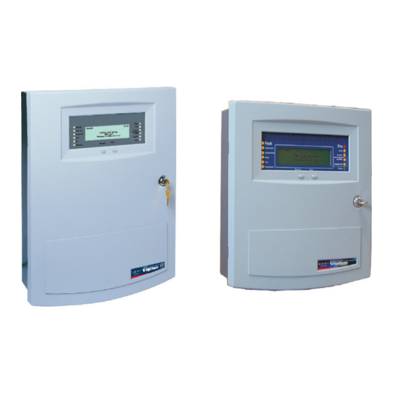
Page 17: Fire Panels
TEST START ALERT TEST END EVACUATE STAND DOWN BOMB EN54 Part 2, 4 & 16 Vigilon by Honeywell COMPACT VOICE 0XXXx Key lock for Access level 1 outer door Controls to scroll events Access level 2 & 3 Pocket for... -
Page 18: Controls And Indications
Commissioning instructions Controls and indications Panel buzzer Vigilon Compact panel or EN Vigilon 4-loop panel or Vigilon Compact Voice Alarm panel (legacy) has CB253 / CB254 LEDs in place of Fire routing LEDs BS Vigilon 4-loop panel BS Vigilon 4-loop panel: NOT USED Zones Zones... - Page 19 Vigilon 4/6 loops & Compact (VA) panels & network nodes Indications applicable for all Vigilon panels Indicators Description Display The Display provides messages of the system status / events by means of 8 lines by 40 characters per line display. Hidden-until-lit fire zones indicators.
- Page 20 Commissioning instructions Controls applicable for all Vigilon panels Controls Description Menu On/Off Pressing Menu On/Off will enable/disable the on screen menu facility which gives access to the system menus. The 'Fn' buttons are used to select functions and sub-functions of the system menus which appear on the display. Each option available at a menu level has an associated function button and on pressing a function button will select the option described on the display.
- Page 21 Vigilon 4/6 loops & Compact (VA) panels & network nodes Controls applicable for Vigilon Compact (& VA) panels only: Controls Description These four buttons are used to scroll the displayed text. These buttons allow data to be entered manually at the control panel. When entering a label each press of a key will scroll the character string, for example: A B C 2 a b c.
- Page 22 Commissioning instructions Controls applicable for Vigilon Compact VA panel only - (legacy product) Pressing one or more of the 10 buttons selects the local Voice Alarm Zone(s) of the local system to which emergency or auxiliary messages, or emergency microphone is to be Voice Alarm Zones announced.
-
Page 23: Vigilon 4/6 Loop Panels
¨ Check that you have the second fix parts, which are supplied with the panel: These procedures assume the respective 1st fix assembly of the Vigilon 4 loop (VIG1-24) / 6 loop EN Vigilon 4 loop EN Vigilon 6 loop (VIG1-72) panel is already installed. -
Page 24: Fitting The Inner Door
Commissioning instructions Fitting the inner door ¨ Locate the hinge pins on the inner door assembly into the two hinge pin holes on the backbox outer face. ¨ Fit the earth lead from the backbox to the inner door spade connector ¨... -
Page 25: Printer Paper Roll
Vigilon 4/6 loops & Compact (VA) panels & network nodes Printer paper roll " The printer paper roll is secured with an elastic band to the card guide on the inner door. ¨ Remove the paper roll from the card guide and install paper into the printer mechanism. Ensure the paper roll enters the printer mechanism as shown. Door Paper roll... -
Page 26: Setting The Dkc Card
Commissioning instructions Control buttons Setting the DKC card " The links, pot and switch on the DKC are factory configured as shown below. DKC ASSEMBLY LCD Contrast adjust Anti-Clockwise - The emergency control buttons must always be left in an enabled state, with the 'control Lighter Danger buttons' link fitted. -
Page 27: Card Installation
Vigilon 4/6 loops & Compact (VA) panels & network nodes Card installation & Backplane When installing cards into the backplane always use anti-static work procedures. DO NOT use anti-static procedures on live equipment. Secure the two ribbon cables (at the fold) under the clamp 40 way ribbon located on the backplane "... -
Page 28: Terminals On Terminal Card
Commissioning instructions Terminals on Terminal Card Terminal card Terminals for Network node CARD 4 CARD 3 CARD 2 CARD 1 RS232 RS232 RS232 RS232 Backplane CTS RX RTS TX CTS RX RTS TX CTS RX RTS TX CTS RX RTS TX NETWORK CARD IN SLOT P8 Terminals for Control panel 0V1 +VE1 -VE1 0V2 N/C +VE2 -VE2 N/C... -
Page 29: Pre Power-Up Checks
Vigilon 4/6 loops & Compact (VA) panels & network nodes ¨ Pre power-up checks The Mains power is switched on after battery is installed and connected. Dedicated mains supply ¨ The mains cable is the only external cable that is required to be connected at this initial stage. from consumer unit Other external circuit cables are left disconnected, but are connected and tested later, they max. -
Page 30: Battery Installation
Commissioning instructions VIG1-72 panel battery installation Battery installation " 4 - 12V 21Ah batteries It is recommended that the mains supply is switched during battery installation. The panel makes use of sealed lead acid type batteries which can have a Battery Box Upper useful life of 5 years or more from the date of manufacture. -
Page 31: Psu Led Indications
Vigilon 4/6 loops & Compact (VA) panels & network nodes PSU LED indications Write protect link on backplane The backplane assembly is fitted inside the left side of the backbox. Ribbon cable The backplane has the card slots to facilitate interconnection of plug-in cards, such as the Main to Terminal Card connector P10 Controller Card (MCC), Loop Processor Cards, IO Cards and Network Cards. -
Page 32: Fire Routing Leds (Post Mid 2015)
Commissioning instructions Fire Routing LEDs (Post Mid 2015) Command Build LEDs CB253 and CB254 (Pre Mid 2015) The Fire Alarm Routing Equipment FARE red LED works The switching of the amber LEDs CB253 or CB254 occurs from a trigger of Command builds 253 or 254. The switching action must be with FARE Interface configured to operate as a FARE configured during commissioning. -
Page 33: How To Configure The 'U' Buttons
Vigilon 4/6 loops & Compact (VA) panels & network nodes How to configure the 'U' buttons Factory settings The U1, U2, U3 and U4 buttons are active at access level 2, that is the buttons are accessible by An EN Vigilon 4/6 loop control panel has the following factory settings: opening the panel outer door. -
Page 34: Vigilon Compact Panel
Commissioning instructions Vigilon Compact Panel The following procedures assume the fire alarm control panel is installed, with cables terminated at the backbox and with the inner and outer doors fitted. Also the protective cover fitted over the Master control board (MCB) inside in the backbox has been removed. ¨... -
Page 35: Cards And Internal Cables Of The Panel
Vigilon 4/6 loops & Compact (VA) panels & network nodes Set the Rotary switch SW2 Cards and internal cables of the panel This switch is set to the required position for the panel build on leaving the factory. Before installing the Loop cards and Network card onto the Master control board MCB ensure the switch SW2 is set to a required setting if Master Control... -
Page 36: Installing A Replacement Mcb In An Older Vigilon Compact Panel
Commissioning instructions Installing a replacement MCB in an older Vigilon Compact panel Remove the cards ¨ Remove the Loop card(s) and Network card# from the MCB and then These instructions cover how to fit a replacement Master Control Board (VCS-MCB-N) into a COMPACT-24-N remove the MCB from the panel. -
Page 37: Terminals On The Master Control Board (Mcb)
Vigilon 4/6 loops & Compact (VA) panels & network nodes Descriptions of MCB terminals Terminals on the Master Control Board (MCB) Terminals Description NC C NO NC C NO NC C NO 24V, 0V, B and A These terminals accept the connection of a repeat indicator panel (Port 0). -
Page 38: Settings On The Dkc
Commissioning instructions Control buttons Settings on the DKC & The links and pot on the DKC are factory configured as shown below. LCD Contrast adjust The emergency control buttons MUST always be left in an enabled state, with the Anti-Clockwise - 'control buttons' link fitted. -
Page 39: Pre Power Up Checks
Vigilon 4/6 loops & Compact (VA) panels & network nodes Pre Power up checks Battery Installation ¨ ¨ The mains cable is the only cable required to be Remove the battery support bracket from the backbox. ¨ connected, with other external cables left Fit the battery lead to the PSU. -
Page 40: Mains Supply
Commissioning instructions PSU Indicators Mains supply PSU BOARD Dedicated mains supply from consumer unit 230V ac Y1 Y2 G1 5A Unswitched fused spur unit 1A P7 BAT1 PANEL DANGER Y1 Y2 G1 FS3 3.15A(T) Mains fuse & Description Ensure the mains supply cable enters the panel enclosure through a (yellow LED) (yellow LED) (green LED) -
Page 41: How To Configure The Monitored Input
Vigilon 4/6 loops & Compact (VA) panels & network nodes PSU EEPROM link How to configure the monitored input Ensure a shorting link is fitted to the programming header P1 located on the PSU. The link must be fitted such that it shorts pins 1 and 2. This enables the EEPROM hardware write protect. Normally open contacts "... -
Page 42: Fire Routing Leds (Post Mid 2015)
Commissioning instructions Fire Routing LEDs (post mid 2015) How to configure the LEDs CB253 and CB254 (pre mid 2015) Pre mid 2015 Post mid 2015 The switching of the amber LEDs CB253 and CB254 is controlled by action of command builds 253 and 254 respectively. The switching action must be configured during commissioning. -
Page 43: How To Configure The U1 And U2 Buttons
Vigilon 4/6 loops & Compact (VA) panels & network nodes How to configure the U1 and U2 buttons External printer An external printer (part number PRINTER-HAND) may be connected to the control panel during commissioning. It is essential that the printer is connected to the RS232 - Port 1. 9-way D-type connector Download lead - 77821-01NM... -
Page 44: Factory Settings
Commissioning instructions Factory settings An EN Vigilon Compact Control panel has the following factory settings: System configuration ¨ All devices are assigned to Sector 1 ¨ All devices are assigned to Zone 1 Port settings ¨ P0 - RS485, Baud: 1200, Mode: Repeat ¨... -
Page 45: Vigilon Compact Voice Alarm Panel - (Legacy Product)
Vigilon 4/6 loops & Compact (VA) panels & network nodes Connect the 40-way ribbon to the socket labelled Mains terminal block Vigilon Compact Voice Alarm Panel - KEYBOARD on MCB and secure cable to the side with fuse of the enclosure. (legacy product) Fit the earth lead to the inner door P Clip for... -
Page 46: Cards And Internal Cables Of The Panel
Commissioning instructions NVM hardware link P13 Cards and internal cables of the panel The NVM can be enabled or disabled by setting the hardware link on the MCB. If the NVM protect is hardware disabled Master Control Audio Control Card (ACC) Board (MCB) then it is possible to software enable or disable the NVM using KEYBOARD INDICATORS AND DISPLAY... -
Page 47: Terminals On The Audio Control Card
Vigilon 4/6 loops & Compact (VA) panels & network nodes AUDIO LOOP 1 AUDIO LOOP 2 PA MIC 1 Terminals on the Audio Control Card O/A O/B I/A O/A O/B I/A PTT1 Descriptions of ACC terminals Terminals Description FOR FUTURE USE These terminals accept the connection of background PA MIC 2 PA2 PTT2... -
Page 48: Terminals On The Master Control Board
Commissioning instructions Descriptions of MCB terminals Terminals on the Master Control Board Terminals Description 24V, 0V, B and A These terminals accept the connection of a repeat indicator panel (Port 0). The power terminals may be used on a Network node to NC C NO NC C NO NC C NO supply BACnet Gateway card. -
Page 49: Battery Installation
Vigilon 4/6 loops & Compact (VA) panels & network nodes Battery Installation " ¨ A battery lead supplied in the spares pack must be fitted to the Power supply board, The panel makes use of sealed lead acid type batteries which can have a connector P7 labelled BAT1. -
Page 50: Mains Supply
Commissioning instructions Mains supply & Hazardous voltage remains after operation of a protection fuse. Take Dedicated mains supply appropriate action to guard against the risk of equipment having exposed live from consumer unit mains supply. 230V ac Audio LEDs 5A Unswitched fused The Audio LEDs on the ACC card are associated with Audio Loop 1 and spur unit Audio Loop 2, to indicate when the audio is active. -
Page 51: How To Check And Set The Audio Signal
Vigilon 4/6 loops & Compact (VA) panels & network nodes How to check and set the audio signal Factory settings Jack sockets An EN VIGILON Compact VA Control panel has the following factory settings: There are two stereo 3.5mm jack sockets on the Audio Control Card labelled Audio 1 and Audio 2. A standard low impedance headphone may be plugged into the each jack sockets to listen to the System configuration audios. -
Page 52: Indications On Power Up
Commissioning instructions Indications on power up Initial tests " These are typical power up indications given at the VIGILON, VIGILON Compact and VIGILON Compact VA panels with no loop circuits connected. The menus at the control panel are accessible by pressing the Menu On/Off "... -
Page 53: Useful Menu Options
Vigilon 4/6 loops & Compact (VA) panels & network nodes Useful menu options Password or PIN code " The menu maps of all the menu options that are accessible at the control panel are detailed in Appendix A. The terms Password, PIN (Personal Identification Number), Usercode and Access code mean the same and are used interchangeably. -
Page 54: How To Create An Engineer Pin
Commissioning instructions How to create an Engineer PIN How to change the Customer PIN " " All the VIGILON range of fire panels with MCC/MCB at V4.53 or greater are The Vigilon and Vigilon Compact panels leave the factory with no Engineer PIN code automatically set up with a FACTORY DEFAULT CUSTOMER PIN: 2 2 2 2, once an (Access level 3 code). -
Page 55: Address Allocation
Vigilon 4/6 loops & Compact (VA) panels & network nodes Address allocation Spur on main loop Main Resonance Search loop Where S-Quad sounder devices manufactured post April 2014 are circuit Spur installed in a system then these devices automatically check that the main components used to produce the sound output are working at their loop... -
Page 56: Allocation Faults
Commissioning instructions Starting Loop n How to re-allocate addresses to a loop circuit Loop started OK at Card X: Started Y ¨ It is possible to selectively commence the address reallocation to devices on a loop circuit:. Even if all the devices are wired correctly and there are no allocation faults, ¨... -
Page 57: Safe Addressing
Vigilon 4/6 loops & Compact (VA) panels & network nodes To SAFE address a device SAFE Addressing # - will appear if a PIN is setup. A SAFE address is an address given to a device during commissioning, the value of which is stored in the non volatile memory within the electronics module of the device, the SAFE address is therefore carried with the device. -
Page 58: Checking A Loop Map
Commissioning instructions To find devices on a loop circuit Checking a loop map Checking physical location of devices on a loop map is made easier by having two people in communication with each other. While one person walks around the site and mark off the devices A loop map is checked against the as fitted wiring drawings. -
Page 59: Non Volatile Memory (Nvm)
Vigilon 4/6 loops & Compact (VA) panels & network nodes NVM Hardware Write protect Non Volatile Memory (NVM) Hardware 'write protect' on a VIGILON 4/6 loop panel Older Vigilon New Vigilon The NVM is located inside the panel on the Backplane of VIGILON panel and on the TERMINALS FOR CARD IN P8 4-loops panel... -
Page 60: Nvm Software - 'Write Protect' And 'Unprotect
Commissioning instructions NVM Software - 'write protect' and 'unprotect' To back up loop data to NVM To 'software' write protect NVM A fully allocated loop should be backed up to the Non Volatile Memory (NVM). The following procedure assumes no password access is required and write protect is disabled. Once the NVM is protected, it is not possible to 'write' or 'backup' card data to NVM. -
Page 61: To Recover Loop Data From Nvm
Vigilon 4/6 loops & Compact (VA) panels & network nodes To recover loop data from NVM How to electrically erase the NVM ¨ & On power-up the information stored on the Non Volatile Memory is automatically recovered to the Local Controller (MCB) and Loop processor cards. Under normal circumstances erasing the NVM is not necessary as If there is a recovery failure you will get the following message: there is only one back up of the complete system configuration data held at the... -
Page 62: 2Km Loop Circuit - Tests Using Ldt
Commissioning instructions 2km Loop circuit - tests using LDT 1km Loop circuit - manual tests Loop diagnostic tool Applicable for panel fitted with VIG-LPC and COMPACT-LPC loop cards The loop circuit tests involve checking the loop circuit resistance, capacitance and then carrying out Applicable for panel fitted with VIG-LPC-EN or COMPACT-LPC-EN cards open circuit, short circuit and break tests. -
Page 63: Loop Circuit Tests
Vigilon 4/6 loops & Compact (VA) panels & network nodes Ground break test Loop circuit tests A ground break test should be carried out at this stage: ¨ Loop short circuit test Disconnect the 0V line from End-1 of a loop circuit. A loop short circuit isolation test should be carried out at this stage. -
Page 64: Positive Line Break Test
Commissioning instructions Positive line break test Earth fault test A positive line break test should be carried out at this Earth fault tests should be carried at this stage: Type of earth fault stage: L1 (+ve) 0V (-ve) LOOP CABLE Interrogate the [PSU] readings using the [Test/Eng] menu ¨... -
Page 65: Checking Device Status
Vigilon 4/6 loops & Compact (VA) panels & network nodes O - Output, I - Input and . signify - not used Checking device STATUS Device digital I / O channels S4 Dual OH/Red VAD O . . O 1, 2, 4, 5 Loop Device Status S4 Heat/Voice Sen Sndr/Red VAD OOOO... - Page 66 Commissioning instructions Device digital I / O channels Device digital I / O channels . . . O The legacy products below are for reference Repeat panel . . . O S-Quad Dual Optical Heat Sensor Strobe O . . O 1, 2, 4, 5 Zonal mimic .
-
Page 67: Plexus Device Status
Vigilon 4/6 loops & Compact (VA) panels & network nodes Plexus Device Status Use the controls at the Vigilon Control panel select [Info] -> Radio Sounder Strobe momentarily selectin order to find and select [Status] -> 15:47 Loop 1 No. 47 Radio Sounder Strobe [Device] and enter the device number or range whose status is I/O:.00O Anal:5,6... -
Page 68: Device Checks
Commissioning instructions Product Analogue Channels Time average Device checks Tnew S4 Heat Sensor 2 - heat " S4 Heat Sensor Sounder 2 - heat Ensure all dust covers have been removed from the sensor heads and the S4 Dual Optical Heat Sensor 1 - optical (forward) system is allowed to operate for at least 24 hours to obtain accurate time average and 2 - heat... - Page 69 Vigilon 4/6 loops & Compact (VA) panels & network nodes S4 Dual OH/Voice Sounder 1 - Optical (forward) 2 - Heat 4 - Optical (backward) S4 OH Sensor Sounder 1 - Optical (forward) 2 - Heat S4 Dual OH Sensor Sounder 1 - Optical (forward) 2 - Heat 4 - Optical (backward)
-
Page 70: Checking The Exception/Subfault Codes
Commissioning instructions Exceptions Meaning Action Checking the Exception/Subfault codes /Condition codes 'Exception' (EN) or 'Subfault' (BS) are condition codes and these codes provide information about a 1 0 0 0 0 0 0 0 0 0 or This is the sub-fire band and No action need be taken. -
Page 71: Condition Codes For S-Quads (Exception / Sub Fault Codes)
Vigilon 4/6 loops & Compact (VA) panels & network nodes Condition Codes for S-Quads (Exception / Sub Fault codes) Condition codes Normal Sub fault band Fault band Pos. band type Description Optical subfire None Small signal sensed Subfire [Check location, state & type] [Check location, state &... -
Page 72: Pre Fire, Fire And Super Fire
Commissioning instructions Pre Fire, Fire and Super fire Definitions Condition meaning..and for State 0 it implies PreFire Fire detection is at a higher sensitivity than the selected STATE. Fire detection that will easily pass the respective EN54 test. Fire Fire detection at the sensitivity of the selected STATE. -
Page 73: S-Quad Sensor With Vad - States Vad (Current Range Of Devices)
Vigilon 4/6 loops & Compact (VA) panels & network nodes S-Quad Sensor with VAD - STATES VAD (current range of devices) The STATE in which an S-Quad sensor operate can be changed from the default factory set STATE to another STATE during commissioning using the Commissioning tool. The environment in which an S-Quad device is installed will determine what STATE is used. -
Page 74: S-Quad Sensor With Strobe - States (Legacy Devices)
Commissioning instructions S-Quad Sensor with Strobe - STATES (legacy devices) The STATE in which the S-Quad sensors operate can be changed from the default factory set STATE to another STATE during commissioning. The environment in which the S-Quad device is installed will determine what STATE is applicable. -
Page 75: S-Quad Heat Sensor States
Vigilon 4/6 loops & Compact (VA) panels & network nodes S-Quad Heat sensor STATES # - factory default STATE Sensitivity State Definition / Class Application in / Suitable for: a-high- to-e-none State 0# Class A1 heat Area having high levels of smoke, dust or steam State 13 Class A2 heat Area where there is moderate temperature changes plus dust, smoke or steam present State 5... -
Page 76: S-Quad Dual Optical, Heat & Co Sensor States
Commissioning instructions S-Quad Dual Optical, Heat & CO sensor STATES Sensitivity State Definition / Class Application in / Suitable for: a-high- to-h-none State 1 High sensitivity optical, Class A1 heat, Clean area or environment where early detection is required with false alarm reduction high sensitivity gas State 4 Medium sensitivity optical with spike... -
Page 77: Beam Sensor States
Vigilon 4/6 loops & Compact (VA) panels & network nodes Beam sensor STATES States verses distance Sensor STATES Ideal range minimum to maximum 4 or 5 2m to 30m 2 or 3 5m to 100m 0 or 1 12m to 100m State Definition Application... -
Page 78: Interface Unit States
Commissioning instructions 4 - Channel Interface Unit STATES Interface Unit STATES These 4 - channel interface unit input STATES are applicable for both mains and loop powered interface units. Single channel interface input STATES STATE Definition Applications These STATES also apply to loop powered single channel interface. State 0 Default - all Inputs enabled Normal use... -
Page 79: 34000 Range Of Sensors States (Legacy Devices)
Vigilon 4/6 loops & Compact (VA) panels & network nodes 34000 range of sensors STATES (legacy devices) & The release of control panel software (MCC/MCB equal to or greater than V4.41): If a non defined STATE is selected during commissioning then the control panel will revert to STATE 0. The previous release of control panel software (MCC/MCB less than V4.41) If a non defined STATE is selected during commissioning then the control panel will revert to STATE 15, which means the device is functionally switched OFF. -
Page 80: Heat Sensor States (34000 Range)
Commissioning instructions STATES Definition Application State 12 (LPC approved) Grade 1 Heat only No optical smoke detection. Can be used where airborne particles or smoke could occur briefly or at specific times. Optical detection can be used in conjunction with time State 13 (LPC approved) Grade 2 Heat only blocks/slots to enable/disable sensor depending on application. -
Page 81: Installed Equipment Tests
Vigilon 4/6 loops & Compact (VA) panels & network nodes Zone 'Test' mode (for EN panels only) Installed equipment tests The Zone Test mode is applicable for EN VIGILON 4/6-loop panel, VIGILON Compact panel and VIGILON Compact VA panel only and is used when testing devices in a zone. It allows the Preparation engineer to test zones without having to return to the panel to silence alarms and reset the system. -
Page 82: Fire Sensors
Commissioning instructions Fire Sensors Interface Units & & 1. When testing heat sensors DO NOT use a heat gun for the test in a hazardous 1. In some instances it may not be possible to functionally test equipment (plant environment. equipment) connected to input / output circuits off an interface unit. -
Page 83: S Cubed
Vigilon 4/6 loops & Compact (VA) panels & network nodes S Cubed Repeat panel (Loop connected) " Each loop repeat panel should be tested for the following: ¨ System event messages and indications are given The remote control is only operable when the panel is in the Zone Test ¨... -
Page 84: Vigilon Compact Network
Commissioning instructions Single Network Vigilon Compact Network ¨ Each standalone system must first be fully commissioned individually. ¨ A VIGILON Compact network can consist of a number of control panels and network nodes wired Check that the correct cable is used to wire the network, the installer's manual lists all together in a secure loop. -
Page 85: Wiring The Single Network
Vigilon 4/6 loops & Compact (VA) panels & network nodes Wiring the single network Single network without domain bridge Vigilon Compact Cable screen Control panel N/C = No connection Network Card Address 2 Baud 38.4K Node 2 PB1B PB1B PB1B PB1A PB1A PB1A... -
Page 86: Network Card For Vigilon Compact - Baud And Node Address Switch Settings
Commissioning instructions Network Card for VIGILON Compact - baud and node address switch settings & The copper network card for use in a Vigilon Compact panel is factory set to 38.4K baud with node address 4. Both node address and Baud rate can be changed to another other setting by configuring the switches on the Network card. -
Page 87: Powering-Up The Network
Vigilon 4/6 loops & Compact (VA) panels & network nodes Powering-up the Network How to check a Network map ¨ ¨ Add one panel at a time starting from the network controller (Node 1) at side 1. Using the Menu On/Off -> [Info] -> [Map] -> [NetMap] option to enter the network card address n. -
Page 88: How To Check Network Card Status
Commissioning instructions How to check Network Card status Errors meaning Freeblock Free memory blocks available to temporarily store messages Using the Menu On/Off -> [Info] -> [Status] -> [Card] and enter the network card address in this waiting to be processed. The maximum number = 199, although it case it is '4'. -
Page 89: Single Vigilon Network
Vigilon 4/6 loops & Compact (VA) panels & network nodes Single Network Single Vigilon Network ¨ Each standalone system must first be fully commissioned individually. ¨ A VIGILON network consists of a number of control panels of standalone systems and network Check that the correct cable is used to wire the network. -
Page 90: Wiring A Copper Network
Commissioning instructions Wiring a Copper network Cable screen From To Next previous panel panel or node or node connection 0V L2- L2+ 0V L1- L1+ 0V1 +VE1 -VE1 0V2 N/C +VE2 -VE2 N/C 0V1 +VE1 -VE1 0V2 N/C +VE2 -VE2 N/C 0V -ve +ve 0V I -ve +ve | Connections for Connections for... -
Page 91: Single Network Without Domain Bridge
Vigilon 4/6 loops & Compact (VA) panels & network nodes Single network without domain bridge Powering-up the Network ¨ Control panel Add one panel at a time starting from the network controller, adding one panel/node at a time to side 1. IO Card "... -
Page 92: How To Check Network Card Status
Commissioning instructions How to check Network Card status Errors meaning Using the Menu On/Off -> [Info] -> [Status] -> [Card] and enter the network card number, usually Time out Where an 8 bit transmission block is not fully received, the this is card number 6 and select [E]. -
Page 93: Multiple Vigilon Networks
Vigilon 4/6 loops & Compact (VA) panels & network nodes Star network using Domain bridge IO cards Multiple Vigilon Networks Domain Bridge using Input Output card If remote sites are residential it is not Two or more VIGILON networks can be connected together at domain bridge IO cards by having a Previous Next Previous... -
Page 94: Io Domain Bridge Network Switch Settings
Commissioning instructions IO domain bridge network switch settings Switch settings on cards inside Control panel Control panel EN54 Vigilon panels / Nodes IO Card IO Card where Domain Bridge IO Card all switches to all switches to is used to network the fire systems Off position Off position Network Card... -
Page 95: Message Routing
Vigilon 4/6 loops & Compact (VA) panels & network nodes Message routing Main controller card (Card 0) will accept all messages from Master group 1 and route messages Message routing at Card 0 domains 2 and 3 Messages All events - 1 Domain 2 - Card 6 via the network card... -
Page 96: Domain Bridge Message Passing Tests
Commissioning instructions Domain bridge message passing tests Domain bridge using Fibre Optic network card To check the domain bridge connections and to ensure messages Up to 64 small VIGILON networks can be connected together in a secure loop by using domain bridge fibre optics network card can be passed between networks the following must be done. -
Page 97: Fo Domain Network Switch Settings
Vigilon 4/6 loops & Compact (VA) panels & network nodes FO Domain Network switch settings Node 3 Node 3 Node 2 Node 2 Node 1 Node 1 Network Card Network Card Domain 1 Domain 2 Address 1 Address 1 Baud 38.4K Baud 38.4K Domain3 Switch settings for Cards... -
Page 98: Appendix A-1 - Menu Maps For En54 (V4) Vigilon Panel
Commissioning instructions Appendix A-1 - Menu maps for EN54 (V4) Vigilon panel The menu options [Control], [SetUp], [Info] and [Test/Eng] are accessible on pressing the MENU ON/OFF button. EN Vigilon Control panel with MCC/MCB V4.53 or higher Access level 1 No menus are accessible at AL1 Access level 2a Control... - Page 99 Vigilon 4/6 loops & Compact (VA) panels & network nodes EN Vigilon Control panel with MCC/MCB at V4.53 or higher [Control] Menu map 2-1 to 2-4 Access level 1 No menus are accessible at AL1 Menus accessible with panel door open Access level 2a Control Menus accessible with panel door open and AL2 password...
- Page 100 Commissioning instructions EN Vigilon Control panel with MCC/MCB at V4.53 or higher Set Up ] Menu map 1 Access level 1 No menus are accessible at AL1 Menus accessible with panel door open Access level 2a Access level 2a Menus accessible with panel door open and AL2 password Access level 2b [Control] [Set Up]...
- Page 101 Vigilon 4/6 loops & Compact (VA) panels & network nodes EN Vigilon Control panel with MCC/MCB at V4.53 or higher Set Up ] Menu map 2-1 and 2-2 Access level 1 No menus are accessible at AL1 Menus accessible with panel door open Access level 2a Setup menu map 2-1...
- Page 102 Commissioning instructions EN Vigilon Control panel with MCC/MCB at Access level 1 No menus are accessible at AL1 V4.53 or higher Menus accessible with panel door open Access level 2a Set up [E] = [Enter] menu map 3 Set Up ] Menu map 3 Menus accessible with panel door open and AL2 password Access level 2b...
- Page 103 Vigilon 4/6 loops & Compact (VA) panels & network nodes EN Vigilon Control panel with MCC/MCB at Access level 1 No menus are accessible at AL1 Menus accessible with panel door open Access level 2a V4.53 or higher Set up Access level 2b Menus accessible with panel door open and AL2 password menu map 4-1...
- Page 104 Commissioning instructions EN Vigilon Control panel with MCC/MCB at Access level 1 No menus are accessible at AL1 Menus accessible with panel door open Access level 2a V4.53 or higher [Control] [Set Up] [Info] [Test/Eng] Menus accessible with panel door open and AL2 password Access level 2b Info ] Menu map...
- Page 105 Vigilon 4/6 loops & Compact (VA) panels & network nodes EN Vigilon Control panel with M CC/MCB at Access level 1 No menus are accessible at AL1 V4.53 or higher Menus accessible with panel door open Access level 2a Menus accessible with panel door open and AL2 password Access level 2b Test/Eng ] Menu map 1...
- Page 106 Commissioning instructions EN Vigilon Control panel with M CC/MCB at V4.53 or higher Test/Eng ] Menu map 2 Access level 1 No menus are accessible at AL1 Menus accessible with panel door open Test/Eng Access level 2a menu map 2-1 Menus accessible with panel door open and AL2 password Access level 2b [Loop]...
-
Page 107: Appendix A-2 - Menu Maps For Bs (V3+) Vigilon Panel
Vigilon 4/6 loops & Compact (VA) panels & network nodes Appendix A-2 - Menu maps for BS (V3+) Vigilon panel The menu options [Control], [SetUp], [Info] and [Test/Eng] are accessible on pressing the MENU ON/OFF button. BS Vigilon Control panel with MCC V3.97 or higher Access level 1... - Page 108 Commissioning instructions BS Vigilon Voice Alarm Control panel with MCC at V3.97 or higher [Control] Menu map 2-1 Access level 1 No menus are accessible at AL1 [E] = [Enter] Menus accessible with panel door open Access level 2a Control [C] = [Cancel] menu map 2-1 Menus accessible with panel door open and AL2 password...
- Page 109 Vigilon 4/6 loops & Compact (VA) panels & network nodes BS Vigilon Control panel with MCC at V3.97 or higher Set Up ] Menu map 1 Access level 1 No menus are accessible at AL1 Menus accessible with panel door open Access level 2a Access level 2a Menus accessible with panel door open and AL2 password...
- Page 110 Commissioning instructions BS Vigilon Control panel with MCC at V3.97 or higher Set Up ] Menu map 2-1 and 2-2 Setup menu map 2-1 Menus accessible with panel door open and AL3 password Access level 3 [Assign] [Remove] Access level 3 [Device] [IO Line] [MCP]...
- Page 111 Vigilon 4/6 loops & Compact (VA) panels & network nodes BS Vigilon Control panel with MCC at V3.97 or higher Set Up ] Menu map 3 Set up menu map 3 Access level 3 Menus accessible with panel door open and AL3 password [Set Up] Access level 3 [Device]...
- Page 112 Commissioning instructions BS Vigilon Control panel with MCC at V3.97 or higher Access level 3 Menus accessible with panel door open and AL3 password Set up menu map 4-1 [Set Up] Menu map 4-1 and 4-2 [Build] Access level 3 [Trigger] [Action] [Label]...
- Page 113 Vigilon 4/6 loops & Compact (VA) panels & network nodes BS Vigilon Control panel with MCC at Access level 1 No menus are accessible at AL1 Menus accessible with panel door open Access level 2a V3.97 or higher [Control] [Set Up] [Info] [Test/Eng] Menus accessible with panel door open and AL2 password...
- Page 114 Commissioning instructions BS Vigilon Control panel with M CC at Access level 1 No menus are accessible at AL1 V3.97 or higher Menus accessible with panel door open Access level 2a Access level 2b Menus accessible with panel door open and AL2 password Test/Eng ] Menu map 1 [Control]...
- Page 115 Vigilon 4/6 loops & Compact (VA) panels & network nodes BS Vigilon Control panel with M CC at V3.97 or higher Test/Eng ] Menu map 2 Access level 1 No menus are accessible at AL1 Test/Eng Menus accessible with panel door open Access level 2a menu map 2-1 Menus accessible with panel door open and AL2 password...
-
Page 116: Appendix B - Message Action List
Commissioning instructions Latching fault events Appendix B - Message Action List The following faults are identified as latching events. ¨ This appendix lists all the messages that are likely to be displayed at the VIGILON control panel / Slave devices lost Network Node. -
Page 117: Message Action List
Vigilon 4/6 loops & Compact (VA) panels & network nodes Message Action list The messages displayed at the control panel, network node or loop repeat panels are given here in an alphanumerical order to provide guidance: ¨ on a 'fault message' ¨... - Page 118 Commissioning instructions Message associated with.. meaning..possible action MCC / MCB Sound alarms button has been pressed. Alarms sounded (main control card/board) Alarms Verified MCC / MCB Alarms verify button has been pressed. (main control card/board) Alarm Zone Disabled / Enabled at card x (loop processor card) Two devices are given the same address.
- Page 119 Vigilon 4/6 loops & Compact (VA) panels & network nodes Message associated with.. meaning..possible action Failure of the Control panel to communicate with If applicable, connect the power supply or ASCII Device is Repeat / Mimic panel. The power supplies to these RESET the Master Repeat Card in the Repeat faulty number x on (loop processor card)
- Page 120 Commissioning instructions Message associated with.. meaning..possible action Device Monitored base does not see end-of-line unit. There is Check the internal wiring, there may be a loose Call point open cct a bad connection to MCP. connection. number x on loop y Call point Device Break glass has been broken or operated with a test...
- Page 121 Vigilon 4/6 loops & Compact (VA) panels & network nodes Message associated with.. meaning..possible action MCC / MCB Time and date has been altered or no time has been If necessary, set the clock using the set up Clock changed / Clock (main control card/board) entered.
- Page 122 Commissioning instructions Message associated with.. meaning..possible action Power supply The DC supply is: Check the mains supply and battery wiring. DC too high / DC too Too high if greater than 164 (32V) Too low if less than 102 (20V) MCC / MCB A Delay Block has been configured.
- Page 123 Vigilon 4/6 loops & Compact (VA) panels & network nodes Message associated with.. meaning..possible action Device Failure of fuse or battery wiring is OC on products like Check and replace if necessary to restore. Device Battery OC mains powered interface unit. number x on loop y Normal value = 27.4V Value is equal to or less than 16V (OC) / greater than...
- Page 124 Commissioning instructions Message associated with.. meaning..possible action Device Internal power rail of mains powered interface unit has Replace the device Device power a value of rectified DC equal to or greater than 32V too high/ restored too low (high) / less than 30V (restored) DC equal to or less than 24V (low) / greater than 26V /restored number x on (restored)
- Page 125 Vigilon 4/6 loops & Compact (VA) panels & network nodes Message associated with.. meaning..possible action Network Network card is back to normal operation, (see also End switching normal end switching disabled) at card x Exception number x on (Exceptions also referred to Change noted in the environment of the device Check the condition codes.
- Page 126 Commissioning instructions Message associated with.. meaning..possible action Pattern match is equal to a Fire or MCP operated or Fire number n loop y conventional detection on IO line of interface operated. channel z (loop processor card) MCC / MCB The Fire reset button has been pressed.
- Page 127 Vigilon 4/6 loops & Compact (VA) panels & network nodes Message associated with.. meaning..possible action Device The input line continues to trigger. Check devices on the IO line. Interface input not Reset number x on loop y channel z Interface Input OC / Device The end-of-line is not seen.
- Page 128 Commissioning instructions Message associated with.. meaning..possible action Any Card Software error. Software errors will activate a system reset. Invalid task delay at card x Ignore single occurrence. Record the event in the log book. Any Card Software error. Software errors will activate a system reset. Invalid task stage Ignore single occurrence.
- Page 129 Vigilon 4/6 loops & Compact (VA) panels & network nodes Message associated with.. meaning..possible action Power supply The ADC value too high. Check PSU values in the [test/eng] menu, Loop voltage too normal reading is 221. Check fuses and replace high/low PSU if necessary.
- Page 130 Commissioning instructions Message associated with.. meaning..possible action MCC / MCB The master alarm has been enabled or disabled If necessary, manually enable or disable the Master alarm (main control card/board) automatically or manually. master alarm using the [control] menu. enabled/disabled Master alarm restored Power supply...
- Page 131 Vigilon 4/6 loops & Compact (VA) panels & network nodes Message associated with.. meaning..possible action Network Card The new address set been read at the particular card. New domain address n at card x NMI’s missed at Software error. Software errors will activate a system reset.
- Page 132 Commissioning instructions Message associated with.. meaning..possible action User attempts to write to a hardware write protected Remove the hardware write protect before NVM is read only (non volatile memory)on writing backplane or MCB Panel in/out of MCC / MCB Commissioning mode switched ON/OFF.
- Page 133 Vigilon 4/6 loops & Compact (VA) panels & network nodes Message associated with.. meaning..possible action Any Card Problem with software, the watchdog will operate the Software errors will activate an automatic Program not running MCC / MCB (main control card/board). system reset.
- Page 134 Commissioning instructions Message associated with.. meaning..possible action Sector is switched ON/OFF. Sector actioned (loop processor card) The sector(s) has been enabled or disabled If necessary, manually enable/disable the sector Sector enabled/ disabled at card x automatically or manually. using the [control] menu. (loop processor card) Radio LRT is finding all of the radio devices Seeking radio devices...
- Page 135 Vigilon 4/6 loops & Compact (VA) panels & network nodes Message associated with.. meaning..possible action Device There is a hardware fault possibly associated with the Replace the device Speech circuit has voice chip on the speech S-Cubed or S-Quad failed Speech circuit Device...
- Page 136 Commissioning instructions Message associated with.. meaning..possible action MCC / MCB A 80 column serial printer is fitted to the panel. System Printer fitted (main control card/board) at card x number y loop z System Printer Lost MCC / MCB (Printer option) at card x number y on loop z MCC / MCB...
- Page 137 Vigilon 4/6 loops & Compact (VA) panels & network nodes Message associated with.. meaning..possible action Panel's Serial Link There is a serial link wiring fault between Vigilon Check the serial link is working, ensure: Voice Alarm comms panel 'Port 1' and DOM/Comprio. Other Vigilon panels ¨...
- Page 138 Commissioning instructions Message associated with.. meaning..possible action MCC / MCB Warning has been removed. Warning cleared (main control card/board) Wiring changed - A test has shown a break on the 0V line. The test is Check wiring of 0V around loop. ground break at card conducted every minute.
-
Page 139: Appendix C - Guidelines For Standalone System Commands
Vigilon 4/6 loops & Compact (VA) panels & network nodes Labels Appendix C - Guidelines for ¨ Labels are given to identify location of areas on a site where products are installed standalone system commands ¨ A previously created label can be modified This appendix provides guidance on factors that must be taken into consideration when applying "... -
Page 140: Long Labels
Commissioning instructions Long labels Long labels having up to 64 characters can be given to devices and command builds. This is achieved by replacing commonly used words with token values (special codes). Tokenised labels :When tokens are decoded, a trailing space is automatically added to the decoded word. Likewise when a label is being tokenised, the word must have a space following it, or be at the end of a line. Therefore a token word cannot be followed with a comma, dash or other such character. - Page 141 Vigilon 4/6 loops & Compact (VA) panels & network nodes GALLERY GARAGE GENERAL HOUSING KITCHEN LAUNDRY LOUNGE OFFICE PLANT RECEPTION RESTAURANT SERVICE SERVICES SHOP STAFF STORE STORES SWITCH SYSTEM TOILET WORKSHOP WARD WAREHOUSE Airport Tokens AIR SIDE ARRIVALS BAGGAGE BRIDGE BUREAU DE CHANGE CUSTOMS CONCOURSE...
- Page 142 Commissioning instructions POINT PREPARATION SHOPPING SITTING STATIONERY SUITE SUPPLY TELEPHONE TRANSFORMER Airport Tokens AIRLINES BONDED CHECK-IN CLORIFIER CONVEYOR CUL-DE-SAC DOMESTIC FORECOURT INFORMATION INTERCONNECTOR INTERNATIONAL RECLAIM SCREENING SECRET SIGN TRAVOLATOR TRUCKING Medical Tokens DISPENSARY Components of the Fire System ASPIRATING INPUT OUTPUT PRESSURE SHUTTER...
-
Page 143: Sectors
Vigilon 4/6 loops & Compact (VA) panels & network nodes ¨ Sectors a Sector that is actioned ON will activate its alarm devices, such as interface outputs, S Cubed, S-Quad and DAU devices. a sector can be configured to give one of three signals •... -
Page 144: Integral Sounder Operation
Commissioning instructions Integral sounder operation A sensor sounder device can have its integral sounder only actioned in the event of a local fire event being detected at the device. ¨ Integral sounder Sector operation (sometimes also called 'flag set' Sector) can be configured using the panel menu commands [SetUp]-> [Sector] -> [Sounder] -> [On] ¨... -
Page 145: Default Fire Plan
Vigilon 4/6 loops & Compact (VA) panels & network nodes Default fire plan Fail safe fire plan ¨ The fire plan on power up is known as ‘one out all out’. This is when Sector 1 is assigned with all devices It is advisable to build a fail safe mechanism when Sectoring. -
Page 146: Delay Blocks
Commissioning instructions ¨ Delay Blocks There can be up to 16 Delay blocks per panel ¨ each Delay block can provide a delay of between 4 seconds to 10 minutes (in 4 second increments) before starting a desired action ACTION ACTION ¨... - Page 147 Vigilon 4/6 loops & Compact (VA) panels & network nodes Resound Delay mode functions There are 4 control settings for Delay mode under [Resound]. These settings control what happens to the delay blocks when the Silence Alarms button is pressed. DELAY At any time ...
-
Page 148: Sound And Resound Alarms Options
Commissioning instructions Sound and Resound alarms options Resound [FIRE] -> ON / OFF setting The FIRE ON/OFF setting under [Resound] controls the way sounders operate when a 2nd or subsequent fire occurs after the alarms have been silenced following 1st fire. Resound FACTORY DEFAULT SETTING SETUP... -
Page 149: Time Slots And Time Blocks
Vigilon 4/6 loops & Compact (VA) panels & network nodes ¨ Time slots and Time blocks each Time slot has to be given an Enable time and a Disable time ¨ MAXIMUM OF 15 PER PANEL each Time slot must be ANDed / ORed to the days of MAXIMUM OF 16 PER PANEL week, (Mon, Tue, Wed, Thu, Fri, Sat, Sun). -
Page 150: Zones
Commissioning instructions Zones Groups ¨ LOOP1 There can be up to 128 Groups ZONE INDICATORS ON THE PANEL (EN system only) Test/Eng ¨ Zones all devices default to Group 1 DEVICES Flashing ZONAL MIMIC PANEL ASSIGNED TO ¨ all local controller events are in Group 0, ie faults, ZONE 4 ZONE 1 ZONE 4... -
Page 151: Zone Tasks
Vigilon 4/6 loops & Compact (VA) panels & network nodes ¨ Zone Tasks a Zone task may be used to control the display of fire messages, to provide: DEVICES IN ONE ZONE ONLY • DISPLAY ALL Common zone label only (this is the default). INDIVIDUAL DEVICES ASSIGNED •... -
Page 152: Command Builds
Commissioning instructions Command Builds • or non-reversible action, (deactioned by another Command build for a non-fire trigger or reset for a fire trigger). NOT-REVERSIBLE ¨ COMMAND BUILD FUNCTIONS the Command build trigger for Zone tasks reside under the zone COMMAND ACTION (INPUT) REVERSIBLE menu/function... -
Page 153: Sounders Configuration
Vigilon 4/6 loops & Compact (VA) panels & network nodes Sounders Configuration Number FAB action SAB action ¨ no output Turns Off selected Outputs The standard alarm devices of each standalone system can be configured for three sound output signals 10mS pulse on selected Outputs ¨... -
Page 154: Auxiliary Relays
Commissioning instructions Auxiliary Relays Radio Device The two Auxiliary relays in the control panel are defaulted to operate on: A Plexus radio device is bound to a LRT and can be configured using the Plexus Commissioning tool in a similar manner to any other system device, however see the following note. •... -
Page 155: Fire Alarm Routing Equipment (Fare)
Vigilon 4/6 loops & Compact (VA) panels & network nodes Fire Alarm Routing Equipment (FARE) " ¨ There can be one FARE Interface per Vigilon System. FARE Interface can be a LV Interface unit S4-34420, but can also be a S4-34450. Where a FARE interface is required to be Other interface units can be configured FARE, these include S4-34440-02, S4-34440-12, S4-34401 and S4-34404. -
Page 156: Fire Protection Equipment (Fpe)
Commissioning instructions Fire Protection Equipment (FPE) " ¨ There can more than one Interface configured FPE application in a Vigilon System. FPE Interface can be a MV Interface unit S4-34411, but can be also be a S4-34415 or S4-34420. Where a FPE interface is required to be disabled Other interface units can also be configured as FPE, these include S4-34440-02, S4-34440-12, S4-34401 and then use the FPE device disablement option. -
Page 157: S-Cubed Mark Iii Or Ii And S-Quad
Vigilon 4/6 loops & Compact (VA) panels & network nodes Sounder function S-Cubed Mark III or II and S-Quad A S-Cubed Mark III and II and S-Quad sounder element can operate in turbo mode if configured Speech function during commissioning to provide further 3dB output. The sound outputs are based on the settings The Mark II or III S-Cubed or S-Quad Speech sounder function is provided by stored messages on of the FABs and SABs at the panel that gives changing levels over 2 seconds duration in 8 time a flash memory chip within the assembly. -
Page 158: Voice And Sounder Mode Pluse Vad/Strobe Action
Commissioning instructions S-Cubed Mark I Voice and Sounder mode pluse VAD/Strobe action " ¨ S-Cubed/S-Quad operating in tone mode allows selection from a range of low and high frequency tones that are outputted according to FAB/SAB settings, see sounders configurations section. The S-Cubed Mark 1 strobe outputs is not compliant to EN54 part 23. -
Page 159: Appendix D - Guidelines For Networked System Commands
Vigilon 4/6 loops & Compact (VA) panels & network nodes ¨ There can be up to a maximum of 64 Master Sectors per Appendix D - Guidelines for Networked system panel commands ¨ a total of 255 Master sectors per network system ¨... -
Page 160: Master Groups
Commissioning instructions Master Groups " Once message passing has been setup for global repeat or mimic PANEL 1 PANEL 2 indication, the local panel will also have to route reset messages to other groups, besides Group 0. MASTER GROUP 1 ¨... -
Page 161: Appendix E - Cards
Vigilon 4/6 loops & Compact (VA) panels & network nodes Appendix E - Cards Refer to the instruction leaflet supplied with each card. 4188-856_issue 7_07/15_Generic Vigilon (Compact + VA) Comms. - Page 162 Do not burn. Gent by Honeywell reserves the right to revise this publication from time to time and make changes to the content hereof without obligation to notify any person of such revisions of changes. Hamilton Industrial Park, Waterside Road, Leicester LE5 1TN, UK Website: www.gent.co.uk...