
Related Manuals for Honeywell OMNI 408


Summary of Contents for Honeywell OMNI 408
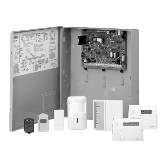
- Page 1 FBII Hardwired/Wireless System OMNI ® -408 OMNI ® -408EU Installation and Setup Guide N9941-2V2 4/04 Rev. A...
- Page 2 The purpose of this guide is to give you a brief overview of the OMNI-408 Control Panel, and provide instructions for installing a basic system. Honeywell is always available to serve YOU. Our SALES AND TECHNICAL SUPPORT staff are available to assist you in any way possible.
-
Page 3: Table Of Contents
Table of Contents • • • • • • • • • • • • • • • • • • • • • • • • • • • • • • • • • • • • • • • • • • • Conventions Used in This Manual ...................... - Page 4 Table of Contents (cont’d) • • • • • • • • • • • • • • • • • • • • • • • • • • • • • • • • • • • • • • • • • • • SECTION 6 –...
-
Page 5: Conventions Used In This Manual
Conventions Used in This Manual • • • • • • • • • • • • • • • • • • • • • • • • • • • • • • • • • • • • • • • • • • • Before you begin using this manual, it is important that you understand the meaning of the following symbols. -
Page 7: Section 1 - Introduction
S E C T I O N Introduction • • • • • • • • • • • • • • • • • • • • • • • • • • • • • • • • • • • • • • • • • • • About the OMNI-408 The OMNI-408 Security System is a state-of-the-art, microprocessor-based control/communicator. -
Page 8: Special Notes
OMNI-408/OMNI-408EU Installation and Setup Guide • 4-wire smoke detectors with fire verification logic plus smoke power reset • 2 entry and 1 exit time delays • Swinger Shutdown capability • Exit Error Warning • European Ring Detect • 128-Event Log History (viewable by PC downloading software and LCD keypad) •... -
Page 9: Section 2 - System Wiring And Hookup
S E C T I O N System Wiring and Hookup • • • • • • • • • • • • • • • • • • • • • • • • • • • • • • • • • • • • • • • • • • • In This Section Wiring the OMNI-408 Auxiliary Device Current Draw Worksheet... - Page 10 OMNI-408/OMNI-408EU Installation and Setup Guide TERMINALS FUNCTION DESCRIPTION Fire Warning System installations, the speaker must be mounted indoors for best audibility. Also, for UL installations, use only one speaker. NOTE: Before connecting sounding devices, consult their specifications for proper current draw. Otherwise, the bell fuse (F1) may be blown. Siren The bell output may be supervised when a conventional bell or a Supervision...
- Page 11 Section 2 - System Wiring and Hookup TERMINALS FUNCTION DESCRIPTION Normally-closed devices may be wired in series; normally-open devices may be wired in parallel. A 2.2k-ohm end-of-line resistor must be installed on all zones even when using zones 1–4 as wireless. (Refer to the wiring diagram.) The standard loop response time is 280 ms on all zones.
-
Page 12: Auxiliary Device Current Draw Worksheet
OMNI-408/OMNI-408EU Installation and Setup Guide BACKUP BATTERY: The Red (+) and Black (-) flying leads must be connected to a 12VDC 4-7AH battery to serve as backup power in the event of AC loss. A battery test occurs approximately every 4.5 minutes. Low-battery conditions occur at nominal 11VDC. -
Page 13: Section 3 - Pc Board Mounting
S E C T I O N PC Board Mounting • • • • • • • • • • • • • • • • • • • • • • • • • • • • • • • • • • • • • • • • • • • In This Section Mounting the Control Board Mounting the Receiver and Antennas... -
Page 14: Mounting The Receiver And Antennas
OMNI-408/OMNI-408EU Installation and Setup Guide ANTENNAS (INSERT IN RIGHT-HAND TERMINALS) RECEIVER DETAILED SIDE VIEW OF BOARD INSERTED INTO SLOTS KNOCKOUT PC BOARD SCREW ANTENNA CABINET GROUNDING CABINET 3rd CLIP REQUIRED DETAILED SIDE VIEW RF RCVR OF CLIP AND BOARD INSTALLED PC BOARD DETAILED SIDE VIEW OF CLIP INSTALLION:... -
Page 15: Section 4 - System Operations
S E C T I O N System Operations • • • • • • • • • • • • • • • • • • • • • • • • • • • • • • • • • • • • • • • • • • • In This Section Power-Up/System Reset Quick Bypass... - Page 16 OMNI-408/OMNI-408EU Installation and Setup Guide STAY STAY TAMPER NO AC TAMPER NO AC PHONE TEST PHONE TEST INSTANT INSTANT NOT READY NOT READY BYPASS BYPASS ALARM ALARM CHIME CHIME FIRE FIRE TRBL PAGE SUPRVSN CANCELED TRBL PAGE SUPRVSN CANCELED XK108 LED Keypad OMNI-KP-US Fixed-Word Keypad OMNI-KP Fixed-Word Keypad NOTE: When using the XK108...
- Page 17 Section 4 – System Operations INSTANT LED This LED/display indicates that the system has been armed in the INSTANT or STAY/INSTANT mode, meaning that the system is currently armed, all delay zones are instant (no entry delay time). Delay zones are currently instant Delay zones are normal See Programming Question 19, Location 1 for various Instant arming options.
-
Page 18: Keypad Sounder
OMNI-408/OMNI-408EU Installation and Setup Guide KEYPAD AUXILIARY KEYS Pressing the auxiliary keys (XK108: two keys labeled P, A, or F at the same time; OMNI-LCD/OMNI- LCD-US/XK7LC/OMNI-KP/OMNI-KP-US: ∗/#, 1/3, 7/9) initiates a CS transmission, if programmed, of programmed functions (e.g., PANIC, AUXILIARY, or FIRE), and causes annunciation of the keypad sounder and turns on the bell output. -
Page 19: Keypad Backlight Timer
Section 4 – System Operations Keypad Backlight Timer The OMNI-KP, OMNI-KP-US, OMNI-LCD, and OMNI-LCD-US keypads have a timer controlled keypad backlight that is on for 120-seconds following a key press (timer on) or constantly on (timer off). Enabling backlight timer: OMNI-KP and OMNI-KP-US: Press the INSTANT and CODE keys at the same time and hold down for two seconds until you hear a beep. - Page 20 OMNI-408/OMNI-408EU Installation and Setup Guide TO ARM: Enter any programmed 4-digit user code. NOTE: The factory default for user 1 is 1234. The ARMED LED will light and the user may exit through an exit/entry zone for the time period programmed as the exit delay.
-
Page 21: Reset
Section 4 – System Operations The system will be armed with the interior zones bypassed and the delay zones instant. NOTE: The STAY/INSTANT mode can be enabled with Programming Question 10, L3. DISARMING TO DISARM: Enter any valid four-digit user code and the ARM LED will extinguish. If an alarm condition exists or occurred while the system was armed, the respective zone LED will blink rapidly. -
Page 22: Quick Bypass
OMNI-408/OMNI-408EU Installation and Setup Guide Quick Bypass Quick Bypass is a programmable option (see Question 07, Location 3 of the programming sequence) that allows the user to bypass zones without using a user code. Press the [BYPASS] key, followed by a number from 1 to 8 which represents the zone to be bypassed. Example: To bypass zone 2, enter: [BYPASS] [2] Exit Bypass... -
Page 23: User Deletion
Section 4 – System Operations Furthermore, if opening/closing by user reporting is programmed, user number 6 will be reported along with the Ambush code. If no CS code is defined in Question 19, then user number 6 will be a normal user code. -
Page 24: Pager Follow-Me Displays
OMNI-408/OMNI-408EU Installation and Setup Guide For example, the 24-Hr Keypad Panic can be initiated by pressing both keypad Panic keys at the same time. The panic condition can be silent (no bell output) or audible, based on the programming option. NOTE: The default value for Panic is audible. -
Page 25: Section 5 - Quick Command Modes
S E C T I O N Quick Command Modes • • • • • • • • • • • • • • • • • • • • • • • • • • • • • • • • • • • • • • • • • • • In This Section Quick Command Mode Listing Display Zone Directory... - Page 26 OMNI-408/OMNI-408EU Installation and Setup Guide Quick Arming [#] [1] If programmed (see Programming Question 07, Location 3), Quick Arming allows arming of the system without entry of a user code, and reports as User No. 8 to the central station if a 2-digit transmission format is defined.
-
Page 27: View Time (Lcd Keypad Only) [#] [7]
Section 5 – Quick Command Modes View Time (LCD Keypad Only) [#] [7] This quick command is always enabled. Pressing [#] [7] will display the date and time in the keypad display. Toggle Pager [#] [8] This quick-command feature provides any user the ability to toggle on or off open/close events, if the events are enabled, by tripping the pager. - Page 28 OMNI-408/OMNI-408EU Installation and Setup Guide 5–4...
-
Page 29: On-Line Download [#] [9]
S E C T I O N Installer Modes • • • • • • • • • • • • • • • • • • • • • • • • • • • • • • • • • • • • • • • • • • • In This Section Entering Installer Modes Installer Mode 4 (On-Line Download) -
Page 30: Installer Mode 2 (Read Only Mode - Keypad Programming)
OMNI-408/OMNI-408EU Installation and Setup Guide Installer Mode 1 (System Default) You can initiate a system default through the keypad by pressing the [1] and [3] keys at the same time while in the Programming mode. The system will then default (revert to factory-programmed values) and go through the reset sequence. -
Page 31: Installer Mode 4 (On-Line Download)
Section 6 - Installer Modes 4. Go to Programming Question 02 by entering [*] [0] [2]. Enter the desired account number, following each digit with [#]. This will be used by the CS downloading computer to determine the proper account information to download to this subscriber. The account number must be 6 digits in length. The downloader's account designator, not the account number, will be communicated to the receiver. -
Page 32: Installer Mode 6 (Clear Tampers)
OMNI-408/OMNI-408EU Installation and Setup Guide Installer Mode 6 (Clear Tampers) This mode clears all tamper displays that have been restored, and it is an engineering reset function. Refer to Question 39, Location 1 to enable. Otherwise, user resets tamper. Installer Mode 7 (System Log View) The system retains history of the past 128 events (alarms, troubles, openings, closings, bypasses, etc.). -
Page 33: Section 7 - System Programming
S E C T I O N System Programming • • • • • • • • • • • • • • • • • • • • • • • • • • • • • • • • • • • • • • • • • • • In This Section General Information Programming Questions - Installer... - Page 34 OMNI-408/OMNI-408EU Installation and Setup Guide QUESTION 00 INSTALLER CODE DEFAULT = 2468 NOTE: When Installer Programming is entered, the system automatically displays Question 01. To display this question for review and/or modification of the Installer Code, enter [✱] + [0] + [0]. Enter the 4-digit Installer Code in Question 00, Locations L1–L4.
- Page 35 Section 7 - System Programming QUESTION 04 ACCOUNT NUMBER 1 DEFAULT = 1234 Enter the 3- or 4-digit subscriber account number for central station phone number 1. If a 3-digit number is used, then enter an “A” as the fourth digit. Valid entries are 0-9, and B-F. The value “A” is interpreted as the null value for account numbers.
- Page 36 OMNI-408/OMNI-408EU Installation and Setup Guide NOTE: The checkmarks highlight which options are selected. HANDSHAKE FORMAT PULSE SPEED FREQUENCY Digit 10 PPS 20 PPS 40 PPS 1400 HZ 2300 HZ PARITY TYPICAL CS RECEIVER FBII, ADEMCO, SILENT KNIGHT FBII FBII FBII, SILENT KNIGHT, ADCOR, ADEMCO FBII FBII, RADIONICS FBII, FRANKLIN, SESCOA, DCI, VARITECH...
- Page 37 Section 7 - System Programming Question 06, L4 K.P. Panic, Swinger Shutdown, Zone Restore, & System Bell Test Default = 1 Enter the digit for the desired system options from the table below in Location L4. NOTE: The checkmarks highlight which options are selected. KEYPAD PANIC SYSTEM DIAL DELAY SWINGER...
- Page 38 OMNI-408/OMNI-408EU Installation and Setup Guide QUESTION 07 KEYPAD CONDITIONS DEFAULT = 1004 This question contains 4 locations (L1-L4). Question 07, L1 Keypad Panic, Fire and Auxiliary Default = 1 Enter the digit for the desired system options from the table below in Location L1. NOTE: The checkmarks highlight which options are selected.
- Page 39 Section 7 - System Programming NOTE: The checkmarks highlight which options are selected. DIALING PULSE TYPE AUTO Digit FAULTED EUROPEAN STAY European Pulse has not been tested for UL installations. ARM FAULTED - If enabled, this allows the user to arm the system independent of the status of any delay or interior zones.
- Page 40 OMNI-408/OMNI-408EU Installation and Setup Guide QUICK FORCED ARMING - Specifies whether Quick Forced Arming ([#] [2]) is permitted. If chosen, Quick Forced Arming arms the system bypassing any faulted zones. Openings/Closings report User no. 8 to the CS if enabled. QUICK ARMING - Specifies whether Quick Arming ([#] [1]) is permitted.
- Page 41 Section 7 - System Programming USER ON-LINE - Enables the end user command ([#] [9]) for the on-line download. This command instructs an end user on how to initiate an on-line download, possibly preventing a service call. BELL TEST FROM RF KEYFOBS - When set, bell test on arming/disarming (refer to Question 8, Location 1) activates only from keyfobs.
- Page 42 OMNI-408/OMNI-408EU Installation and Setup Guide Digit EXIT TIMEOUTS Digit EXIT TIMEOUTS 1 second 1 minute 20 seconds 10 seconds 1 minute 30 seconds 20 seconds 1 minute 40 seconds 30 seconds 1 minute 50 seconds 40 seconds 2 minutes 50 seconds 2 minutes 10 seconds 1 minute 2 minutes 20 seconds...
- Page 43 Section 7 - System Programming QUESTION 09 MISCELLANEOUS SYSTEM OPTIONS DEFAULT = 2C06 There are 4 locations (L1-L4) for system timing and system options, as follows: Question 09 L1 Entry Delay 2 Default = 2 Using the table in Question 8, Location 1 to determine valid choices, enter the desired entry delay time for zones 4-8.
- Page 44 OMNI-408/OMNI-408EU Installation and Setup Guide CS TEST TIME INTERVAL - There are 2 modes of test transmission for the CS Test Time Interval. One mode is reset by an event and the other mode operates only by time, as described below. Enter the CS code in Question 21, Locations 3 and 4.
- Page 45 Section 7 - System Programming followed by the 2-digit RF question number to access the RF questions. If the bit IS enabled, the procedure now is to press the [BYPASS] key followed by the 2-digit RF question number. RF TROUBLE SOUNDER - Choosing this option causes the keypad sounder to pulse until either a valid user is entered or the trouble is restored, in the case of a RF low battery, RF supervision, or RF tamper condition.
- Page 46 OMNI-408/OMNI-408EU Installation and Setup Guide DISARM BELL TEST - Choosing this option causes a 1-second bell output when system disarms (or a single chirp if the Bell Test Chirp option is selected). BELL TEST CHIRP - This option is for use with sirens that respond quickly to an output. If selected, this option shortens both the Arming Bell Test (double chirp) and Disarm Bell Test (single chirp) from a 1-second to a 100-mS output.
- Page 47 Section 7 - System Programming Question 10, L3 Arm Instant, Arming Stay Instant, Instant Key Arms Away, Stay Key Arms Stay Default = 0 ARM INSTANT ARM STAY/ INSTANT KEY - STAY KEY - Digit ENABLE INSTANT ENABLE ARMS AWAY ARMS STAY NONE ARM INSTANT ENABLE - If selected, this option allows the system to be armed in the Instant mode.
-
Page 48: Zone Programming
OMNI-408/OMNI-408EU Installation and Setup Guide Question 10, L4 Pager Events Default = 0 Digit ALARMS TROUBLES OPEN CLOSE NOTES: NONE • Pager alarms are limited to zone alarms only. Pager troubles are limited to zone troubles only (fire trouble, day trouble, 24-hr trouble). - Page 49 Section 7 - System Programming BURGLARY (CONTROLLED) ZONES ZONE TYPE ZONE OPTIONS L1, L2 INSTANT DELAY INTERIOR BYPASS DIALER Digits (PERIMETER) (EXIT/ENTRY) FOLLOWER CHIME IN STAY DELAY None (Instant Zone w/o Options) None (Delay Zone w/o Options) None (Interior Zone w/o Options) Burglary (Controlled) Zones DELAY - This is the industry standard exit/entry zone.
- Page 50 OMNI-408/OMNI-408EU Installation and Setup Guide INTERIOR - All interior zones have exit delay time upon system arming. Furthermore, all interior zones have entry delay time if a delay zone is violated first. If this zone is violated first, however, it generates an immediate alarm.
- Page 51 Section 7 - System Programming 24-HOUR ZONES ZONE TYPE ZONE OPTIONS L1, L2 24-HOUR 24-HOUR Digits ALARM FIRE TROUBLE AUDIBLE SILENT Always Audible 24-Hour Zones FIRE - Fire zones on the system contain Fire Verification Logic. Upon detection of the first violation, smoke detector power is reset for a period of 8 seconds.
- Page 52 OMNI-408/OMNI-408EU Installation and Setup Guide Zone Alarm Codes As specified previously, locations L3 and L4 of the zone questions represent the Alarm code that is reported to the central station. NOTE: Zones transmit to the central station unless these digits are defined as AA for any individual zone;...
- Page 53 Section 7 - System Programming QUESTION 12 ZONE 2 TYPE & CS CODE DEFAULT = 4132 Question 12, L1 & L2 - Zone 2 Type Default = 41 Question 12, L3 & L4 - CS Code for Zone 2 Default = 32 Zone 2 = Interior Follower w/CS Reporting code = 32 QUESTION 13 ZONE 3 TYPE &...
- Page 54 OMNI-408/OMNI-408EU Installation and Setup Guide QUESTION 19 CS CODES for AMBUSH and AC LOSS DEFAULT = AAAA There are 4 locations (L1-L4) in this question as follows: Question 19, L1 & L2 - Ambush Code Default = AA If an Ambush code is defined, User no. 6 is the Ambush code. The same rules apply here regarding dialer format.
- Page 55 Section 7 - System Programming QUESTION 22 CS CODES for BYPASS, RESTORE, TROUBLE and CANCEL DEFAULT = AAFA There are 4 locations (L1-L4) in this question: Question 22, L1 - Bypass Code Default = A L1 is the single-digit system Bypass code that upon arming is reported to the central station if a zone is bypassed.
- Page 56 OMNI-408/OMNI-408EU Installation and Setup Guide Question 24, L3 - RF Supervisory Default = A Question 24, L4 - RF Supervisory Restore Default = A NOTE: In any Question 24 location, if a 2-digit format has been programmed, the second digit of the respective Zone code follows this code.
- Page 57 Section 7 - System Programming RF zone numbers must begin after assigned hardwired zone numbers. For example, if zones 1 through 4 were hardwired, the first RF zone number assigned is 5. RF has not been evaluated by UL and must not be used for UL installations. Any zone using an RF point must be enabled in this question so that the system knows where to look for zone data.
- Page 58 OMNI-408/OMNI-408EU Installation and Setup Guide #58 COMMAND: When selected, enables user’s access to the #58 quick command to enter or change the Pager Follow-Me phone number. If this feature is not enabled, the user will not be able to enter or change a pager phone number.
- Page 59 Section 7 - System Programming Question 27, L3 & L4 - Tamper Disable RF Zones Default = 00 From the tables below, select the RF Zones where tamper is to be disabled. NOTE: The checkmarks indicate which points are selected. L3 - Tamper Disable Zones 5-8 L4 - Tamper Disable Zones 1-4 TAMPER DISABLED ZONES...
- Page 60 OMNI-408/OMNI-408EU Installation and Setup Guide L1 – Arming Options NO ARM IF NO ARM IF RF JAM AC NOT NO ARM IF NO ARM IF RF Digit PRESENT PRESENT BATTERY FAILS SUPERVISED None Question 28, L2 – Jamming Options Default = 0 In location L2, enter the desired system options from the following table.
- Page 61 Section 7 - System Programming Jam Type: The jam type defines the criteria that the jam signal must meet to be considered a valid jamming signal. The types are as follows: EUROPEAN (Euro): If a jam signal is detected for a total of 30 seconds in a 60-second period (not necessarily in one continuous stretch), then qualify it as a jam condition and report it.
- Page 62 OMNI-408/OMNI-408EU Installation and Setup Guide expires, the Exit Error code is not sent. If an alarm results, the zone’s Alarm code is sent before the Exit Error code. RECENT PANIC CS REPORTING - This feature is intended to reduce false alarms. Enable this feature by placing a CS Report code other than "A"...
- Page 63 Section 7 - System Programming QUESTION 32 RF REMOTE KEYFOB 2 BUTTON DEFINITIONS DEFAULT = 0000 Question 32, L1 - RF Remote Keyfob 2 Button 1 Default = 0 Question 32, L2 - RF Remote Keyfob 2 Button 2 Default = 0 Question 32, L3 - RF Remote Keyfob 2 Button 3 Default = 0 Question 32, L4 - RF Remote Keyfob 2 Button 4...
- Page 64 OMNI-408/OMNI-408EU Installation and Setup Guide In locations L1-L4, enter the digit for the desired system options from the table above. See Figure 6 for keyfob buttons. 5804 KEYFOB 5801 KEYFOB 5803 KEYFOB 5802MN KEYFOB Figure 6. Keyfob Buttons QUESTION 36 RF REMOTE KEYFOB 6 BUTTON DEFINITIONS DEFAULT = 0000 Question 36, L1 - RF Remote Keyfob 6 Button 1...
- Page 65 Section 7 - System Programming Digits NON- TRIGGER TYPE DEFINITION DESCRIPTION OF OPERATION INVERT INVERT Smoke Power (Trigger #1 Only) Used in fire verification to reset smoke power Smoke Power - No Verification Used to power smoke detectors with no verification 2-Way Voice See below Burglary Bell Trigger...
- Page 66 OMNI-408/OMNI-408EU Installation and Setup Guide QUESTION 38 CS TEST TIME DEFAULT = 0000 If the control panel transmits a system test at a specific time of day, enter the hour and minute in military time (24-hour clock) as follows: Question 38, L1 & L2 - Hour of Day (00 - 23) Default = 00 Enter the hour of the day in military time: 00 (12 A.M.) –...
-
Page 67: Zone And System Descriptor Programming
Section 7 - System Programming Question 39, L2 – Language Options Default = 0 LANGUAGE NO PC IF KEY TAMPER ARMED LOCK Digit ENGLISH SEE NOTE SPANISH NOTE: When this selection is made, the selected language is as follows. OMNI-408 = Portuguese OMNI-408EU = Dutch No PC if Armed: If system is armed, the control will not communicate with downloading computer. - Page 68 OMNI-408/OMNI-408EU Installation and Setup Guide Function INSTANT Accepts displayed character and moves cursor forward one position. CODE Moves cursor backward one position. Displays next character in character set. Displays previous character in character set. [#] [7] Automatically scrolls character set display forward. [#] [9] Automatically scrolls character set display backward.
-
Page 69: Section 8 - Programming Questions - Rf Programming
S E C T I O N Programming Questions - RF Programming • • • • • • • • • • • • • • • • • • • • • • • • • • • • • • • • • • • • • • • • • • • NOTE: You must be in Installer Mode Programming to perform the following. - Page 70 OMNI-408/OMNI-408EU Installation and Setup Guide Question 13 RF Keyfob 5 Serial Number Default = 000000000 CS User Number 12 Function Q34 Select the options for Keyfob 5 in L1 - L9. Enter the valid digits from the tables below. Question 14 RF Keyfob 6 Serial Number Default = 000000000 CS User Number 13 Function Q35 Select the options for Keyfob 6 in L1 - L9.
- Page 71 Section 7 - System Programming DESCRIPTION KEYPAD ENTRY 1. Enter RF programming *# or Bypass 2. Select question 09 for keyfob 1 3. Select the 4-button keyfob option (Table L1- RF Device Options) 4. Select 5800 transmitter type (Table L2 - RF Device Type) 5.
- Page 72 OMNI-408/OMNI-408EU Installation and Setup Guide 8–4...
-
Page 73: Section 9 - Data Entry Via Keypads
S E C T I O N Data Entry Via Keypads • • • • • • • • • • • • • • • • • • • • • • • • • • • • • • • • • • • • • • • • • • • In This Section General Information Data Entry via Fixed-Word Keypad... - Page 74 OMNI-408/OMNI-408EU Installation and Setup Guide AC/LB READY Question Number Stay Instant COVER OPEN Bypass Code STAY INST Data TX LB RF. SPVR XK108-001-V0 Figure 7. Keypad Programming Question Numbers = Zone LEDs Zone LEDs 1 through 5 display the current question number (not the specific location within each question).
- Page 75 Section 9 - Data Entry Via Keypads Stay lit, Inst, Tx Lb and RF Sprv off = 1 Stay and Inst lit, Tx Lb and RF Sprv off = 3 Inst and RF Sprv lit, Stay and Tx Lb off = A The following chart shows binary values that you will see on these LEDs for the letters A-F that may be entered in some locations of the program sheet.
-
Page 76: Data Entry Via Lcd Keypad
OMNI-408/OMNI-408EU Installation and Setup Guide VALUE KEYSTROKES VALUE KEYSTROKES [Code] [1] [Code] [4] [Code] [2] [Code] [5] [Code] [3] [Code] [6] Example: To enter an A, press the [Code] key followed by the [1] key. Question Acknowledgment The keypad chirps on each keystroke. In addition, a beep confirms advancement between question numbers. - Page 77 Section 9 - Data Entry Via Keypads Entering Data This section of the guide describes the physical keystrokes to enter the data written on the program sheet. Movement Between Questions System Program mode starts with question 1 displayed. Direct jumps to any question can be made by pressing the [*] key and the 2-digit question number for system questions or by pressing the [*] key followed by the [#] key and then the 2-digit question number for RF questions.
-
Page 78: Data Entry Via Fixed-Word Keypad
OMNI-408/OMNI-408EU Installation and Setup Guide Data Entry via Fixed-Word Keypad The following paragraphs provide an explanation of how to use a Fixed-Word keypad for data entry. Enter Programming Mode via Keypad The System Programming mode can be entered ONLY WHILE DISARMED, as follows: To enter Installer Programming: Press [Code] [*] 4-digit Installer code (default 2468). - Page 79 Section 9 - Data Entry Via Keypads Data Entry To alter the value in any location, enter the desired digit from the program sheet, then press the [#] key to advance to the next location, or if no further changes need to be made, press [Stay] to exit programming.
-
Page 80: Summary Of System Programming
OMNI-408/OMNI-408EU Installation and Setup Guide Summary of System Programming TO ENTER PROGRAMMING: [Code] [*] 4-digit Installer Code [1] LEDs illuminate steadily in normal programming mode. TO ENTER RF PROGRAMMING (if RF Programming using [Bypass] key is selected): [Bypass], 2-digit Question Number Question LEDs pulse in RF Programming mode. -
Page 81: Section 10 - Summary Of Keypad Functions
S E C T I O N Summary of Keypad Functions • • • • • • • • • • • • • • • • • • • • • • • • • • • • • • • • • • • • • • • • • • • In This Section User Functions Installer Modes... - Page 82 OMNI-408/OMNI-408EU Installation and Setup Guide Installer Modes KEYPAD PROGRAMMING: [CODE] + [✱] + Installer Code + [1] SYSTEM DEFAULT: [CODE] + [✱] + Installer Code + [1], then press [1] + [3] at the same time DEFAULT USER CODES: [CODE] + [✱] + Installer Code + [1], then press [7] + [9] at the same time READ ONLY MODE: [CODE] + [✱] + Installer Code + [2]...
-
Page 83: Appendix A - Central Station Reporting Formats
A P P E N D I X Central Station Reporting Formats • • • • • • • • • • • • • • • • • • • • • • • • • • • • • • • • • • • • • • • • • • • This security system is designed to transmit data to a central station receiver when an alarm, system trouble, or an opening/closing occurs. -
Page 84: Extended (3X1 Ext. Or 4X1 Ext
OMNI-408/OMNI-408EU Installation and Setup Guide 3X1 w/o Paritiy 3X1 w/Parity 123 3 (1st round) 123 3 6 (single round) 123 3 (2nd round) 123 3 (resulting data) 123 3 (resulting data) 4X1 w/o Parity 4X1 w/Parity 1234 3 (1st round) 1234 3 2 (single round) 1234 3 (2nd round) 1234 3 (resulting data) -
Page 85: Partial Extended (3X1 Part. Ext. Or 4X1 Part. Ext
Appendix A - Central Station Reporting Formats Partial Extended (3X1 Part. Ext. or 4X1 Part. Ext.) The Partial Extended Reporting Format: AAA EZ or AAAA EZ Where: AAAA = 3- or 4-digit account number (Program Questions 05 and 06) E = Single-digit Event code; it is the first of the 2 programmable Reporting code digits Z = Zone or user identifier;... -
Page 86: 4X2 Express
OMNI-408/OMNI-408EU Installation and Setup Guide 4X2 Express The 4X2 Express Reporting Format: AAAA EZ Where: AAAA = 3- or 4-digit account number (Program Questions 05 and 06) E = Single-digit Event code; it is the first of the 2 programmable Reporting code digits Z = Zone or user identifier;... - Page 87 Appendix A - Central Station Reporting Formats For some reporting codes, the first of the two programmable digits determines the PID Event code to be transmitted. Other reporting codes transmit a dedicated PID Event code regardless of the digit programmed in the first location. In both cases, if transmissions are not desired, program AA in Locations 1 and 2.
- Page 88 OMNI-408/OMNI-408EU Installation and Setup Guide KEYPAD ZONE TYPES DEDICATED CODES (Fire,* Panic,* Aux.,* Ambush) EVENT ENGLISH OUTPUT AT CS EVENT ENGLISH OUTPUT AT CS CODE RECEIVER Digit CODE RECEIVER Day Trouble Medical 301* AC Loss Pendant Transmitter 309* Battery Test Fail Fire Alarm 321* Trouble Bell...
-
Page 89: Appendix B - Omni-408 System Programming Worksheet
A P P E N D I X OMNI-408 System Programming Worksheet • • • • • • • • • • • • • • • • • • • • • • • • • • • • • • • • • • • • • • • • • • • Name: ____________________________ Address: _________________________________ Account Number: __________________ Programmed by: ___________________________ Installer Mode Programming... - Page 90 OMNI-408/OMNI-408EU Installation and Setup Guide 15 ZONE 5 TYPE AND CS CODE 27 NONSUPERVISED/TAMPER RF ZONES Default: 1035 Default: 00A0 28 ARMING JAM OPTIONS 16 ZONE 6 TYPE AND CS CODE Default: 00AA Default: 1036 29 CID GROUP NUMBER 17 ZONE 7 TYPE AND CS CODE Default: AAAA Default: 1037 30 EXIT PROGRAM/EXIT ERROR/RECENT PANIC...
- Page 91 Appendix B – Omni-408 System Programming Worksheet 41 ZONE 1 DESCRIPTOR Default: ZONE 1 42 ZONE 2 DESCRIPTOR Default: ZONE 2 43 ZONE 3 DESCRIPTOR Default: ZONE 3 44 ZONE 4 DESCRIPTOR Default: ZONE 4 45 ZONE 5 DESCRIPTOR Default: ZONE 5 46 ZONE 6 DESCRIPTOR Default: ZONE 6 47 ZONE 7 DESCRIPTOR...
-
Page 92: Rf Mode Programming
OMNI-408/OMNI-408EU Installation and Setup Guide RF Mode Programming TO ENTER RF PROGRAMMING: Questions 01-14, L1 - RF Device Options Press [*] [#] 2-digit Question Number; or [BYPASS] Digit Option Explanation 2-digit Question Number DISABLED NOT APPLICABLE 1 Zone or Button Only 1 Zone or 1 Button Question LEDs pulse in RF programming mode. -
Page 93: Appendix C - Warnings And Limitations
A P P E N D I X Warnings and Limitations • • • • • • • • • • • • • • • • • • • • • • • • • • • • • • • • • • • • • • • • • • • Warning Limitations of This Alarm System While this system is an advanced design security system, it does not offer guaranteed protection against burglary, fire, or other emergency. - Page 94 OMNI-408/OMNI-408EU Installation and Setup Guide • Alarm warning devices, such as sirens, bells, or horns, may not alert people or wake up sleepers who are located on the other side of closed or partly open doors. If warning devices sound on a different level of the residence from the bedrooms, then they are less likely to waken or alert people inside the bedrooms.
-
Page 95: Appendix D - Regulatory Statements
A P P E N D I X Regulatory Statements • • • • • • • • • • • • • • • • • • • • • • • • • • • • • • • • • • • • • • • • • • • RADIO FREQUENCY EMISSIONS STATEMENTS FEDERAL COMMUNICATIONS COMMISSION (FCC) Part 15 This device complies with part 15 of the FCC rules. - Page 96 OMNI-408/OMNI-408EU Installation and Setup Guide TELEPHONE/MODEM INTERFACE STATEMENTS (continued) INDUSTRY CANADA (continued) Users should ensure for their own protection that the electrical ground connections of the power utility, telephone lines and internal metallic water pipe system, if present, are connected together, This precaution may be particularly important in rural areas.
- Page 97 Appendix D – Regulatory Statements TELEPHONE OPERATIONAL PROBLEMS In the event of telephone operational problems, disconnect the control by removing the plug from the RJ31X wall jack. We recommend that your certified installer demonstrate disconnecting the phones on installation of the system. Do not disconnect the phone connection inside the control/communicator. Doing so will result in the loss of your phone lines.
- Page 98 OMNI-408/OMNI-408EU Installation and Setup Guide D–4...
-
Page 99: Appendix E - Warranty
Seller shall have no obligation under this Limited Warranty or otherwise if the product(s) is altered or improperly repaired or serviced by anyone other than Honeywell factory service. For warranty service, return product(s) transportation prepaid, to Honeywell Factory Service, 165 Eileen Way, Syosset, New York 11791. - Page 100 OMNI-408/OMNI-408EU Installation and Setup Guide E–2...
- Page 101 A P P E N D I X Summary of Connections • • • • • • • • • • • • • • • • • • • • • • • • • • • • • • • • • • • • • • • • • • • ANTENNA 2 ANTENNA 1 JP1 JP2...
- Page 102 OMNI-408/OMNI-408EU Installation and Setup Guide NOTES: DETAIL A 180mA max. for UL installations. CONTROL PANEL SMOKE 650mA max. for UL installations. POWER DETECTOR Connect control panel to a grounded metal water pipe (16 9.5 - 12.2VDC gauge at 15 ft.). Total aux.
- Page 104 165 Eileen Way, Syosset, New York 11791 Copyright © 2004 Honeywell International Inc. www.honeywell.com/security ÊN9941-2V2"Š N9941-2V2 4/04 Rev. A...