Table of Contents
Table of Contents

Related Manuals for Honeywell CM737


Summary of Contents for Honeywell CM737
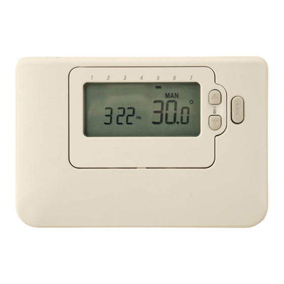
- Page 1 Operator control panel Honeywell CM737 User instruction DOC-1523-EN, Oct 2016...
-
Page 3: Table Of Contents
Room thermostat CM737 ...................... 2 Installing the room thermostat ........................3 Installing the outdoor temperature sensor (option) ...................5 Starting up and component control of the room thermostat CM737 ............5 Configure the room thermostat after installation ..................5 Setting the date ............................6 Setting the time............................6 Operating the room thermostat CM737 ................ -
Page 4: Room Thermostat Cm737
1 Room thermostat CM737 The operator control panel CM737, controls the supply temperature to the heating system. When connecting the unit to the power supply, CM737 verifies the connected sensors and then automatically chooses to control by room or outdoor temperature sensor. -
Page 5: Installing The Room Thermostat
CM737 User instruction Installing the room thermostat Before installation make sure that the electrical power supply is disconnected. Install the room thermostat in the living space according to following: A suitable installation is about 1.5 meters above floor and on an inner wall. - Page 6 CM737 User instruction Picture 3...
-
Page 7: Installing The Outdoor Temperature Sensor (Option)
By outdoor temperature compensation this change represents a standard parallel shift of the heat curve, recalculated for room temperature. Configure the room thermostat after installation CM737 can be configured in three different ways. All installation parameters can be found in the parameter list under category 1, see 3.2 Category 1 parameters: Room Thermostat Settings. -
Page 8: Setting The Date
CM737 User instruction Setting the date 1. Press the DATE/DAY button to begin setting the date. When you set the date for the first time after the batteries are inserted, the display will show: Press the buttons to set the current day of the month (e.g. -
Page 9: Operating The Room Thermostat Cm737
Using this mode is the best way to maintain a high level of temperature comfort whilst maximising the energy savings. MAN (manual) mode sets the CM737 to act with a fixed set point throughout the day. The set point can be adjusted from 5°C to 35°C by using the buttons. -
Page 10: Reviewing The Heating Program
CM737 User instruction Reviewing the Heating Program To review or edit the heating program use the PROGRAM buttons to navigate between the four individual programming periods for that day Use the DAY button to step through each day of the week, so the complete 7 day heating program can be reviewed or edited. -
Page 11: Disabling/Enabling Time Periods
The CM737 will now control to the new temperature for the set number of days that the home is vacant. At midnight the holiday counter will be reduced by one until the selected number of days have passed. The CM737 will then re-turn to normal operation as set by the MAN or AUTO mode. -
Page 12: Otc Heating Curve
CM737 User instruction OTC heating curve The CM737 controls the indoor temperature as a function of the measured outside air temperature. The heating curve is the ratio between the measured outside air temperature and the calculated supply water temperature. The ideal heating curve is dependent on the type of installation (radiators, convectors, etc.), the thermal... -
Page 13: Activation Of Installer Parameters
CM737 User instruction 3 Activation of installer parameters Installer Mode is used to alter the system settings for specific applications, to use the special features of the room thermostat in a different way or to alter the factory present parameters. -
Page 14: Category 1 Parameters: Room Thermostat Settings
CM737 User instruction Category 1 parameters: Room Thermostat Settings Parameter Para Factory Default Setting Optional Setting meter Display Description Display Description 12 hr – AM/PM clock display AM-PM / 24hr 1:CL 24 hr clock display Display format format Reset Time/ Temp... -
Page 15: Category 2 Parameters: System Settings
CM737 User instruction Category 2 parameters: System Settings Parameter Para Factory Default Setting Optional Setting meter Display Description Display Description Summer heating in 1:SH Summer heating 1 to 40 Minimum set point for the OTC mode disabled heating and the pump will be held on. -
Page 16: Category 4 Parameters: Transparent Bolier
Only available if the outside temperature sensor is mounted. Category 4 & 5 parameters are only available if supported by the heating appliance. This will depend on the type of boiler electronics in the heating appliance connected with the CM737. Notes: Always remember to press the green button to confirm that you want to store the new Installer Set-Up setting. -
Page 17: Troubleshooting The Cm737
CM737 User instruction 4 Troubleshooting the CM737 Symptom Possible Cause Remedy The CM737 receives power The CM737 is not connected to supply from the heating the correct terminals of the A flashing symbol appliance, but no information. heating appliance. appears on the display within... -
Page 18: Fault Codes On The Cm737
CM737 User instruction Fault Codes on the CM737 If a spanner is visible on the display there is an on ongoing alarm. Press the Info-button to view the fault code. Error source Error code No fault (power-up) Supply water temperature sensor out of range...