Table of Contents

Related Manuals for Honeywell Fire-Lite Alarms MS-9050UD


Summary of Contents for Honeywell Fire-Lite Alarms MS-9050UD
- Page 1 PN: 52413:C ECN 07-758 Addressable Fire Alarm Control Panel MS-9050UD & MS-9050UDC IMPORTANT! The SLC Manual Document #51309 must be referenced in addition to this manual when installing or servicing the Fire Alarm Control Panel. Document #52413 01/23/08 Revision:...
- Page 2 While a fire alarm system may lower insurance Fire Alarm System Limitations rates, it is not a substitute for fire insurance! An automatic fire alarm system–typically made up of age of flammable materials, etc.). smoke detectors, heat detectors, manual pull stations, Heat detectors do not sense particles of combustion and audible warning devices, and a fire alarm control panel with alarm only when heat on their sensors increases at a...
- Page 3 Adherence to the following will aid in problem-free Installation Precautions installation with long-term reliability: WARNING - Several different sources of power can be Like all solid state electronic devices, this system may connected to the fire alarm control panel. Disconnect all operate erratically or can be damaged when subjected to sources of power before servicing.
-
Page 4: Table Of Contents
Table of Contents Product Description ..............................12 Features and Options ............................12 Specifications ..............................13 Current Availability ............................14 Controls and Indicators ............................15 Circuits ................................15 Digital Alarm Communicator/Transmitter ......................16 Components ...............................17 Intelligent Addressable Detectors: Newer Series ..................17 Intelligent Addressable Modules: Newer Series ..................17 300 Series Intelligent Addressable Devices ....................17 Device Accessories .............................17 Optional Modules ..............................18 Accessories ................................18... - Page 5 Table of Contents Digital Communicator ..........................36 Telephone Company Rights and Warnings ....................37 For Canadian Applications .........................38 Installation ................................39 Mounting Backbox ............................39 Mounting Chassis/Transformer/Main Circuit Board ..................40 Power .................................43 AC Power and Earth Ground Connection ....................43 Battery Power .............................43 Relays ................................44 Notification Appliance Circuits .........................44 Configuring NACs .............................45 UL Power-limited Wiring Requirements ......................46...
- Page 6 Table of Contents PAS (Positive Alarm Sequence) Delay ....................93 Pre-signal Delay ..........................94 Waterflow Delay ..........................94 AC Loss Delay ............................95 NAC (Notification Appliance Circuit) ....................95 Enabled ..............................96 Type ..............................97 Silenceable ............................97 Auto Silence ............................98 Coding (only for NACs not programmed as Sync Strobe Type) ............98 Zone ..............................100 Silence Inhibited ..........................100 Sync Type ............................100...
- Page 7 Table of Contents Supervisory Operation ............................152 Process Monitor Operation ..........................153 Hazard/Tornado Condition Operation .......................153 Medical Alert Condition Operation ........................153 NAC Operation ..............................153 Programmed Zone Operation ..........................154 Disable/Enable Operation ..........................154 Waterflow Circuits Operation ..........................154 Detector Functions ............................154 Time Functions: Real-Time Clock ........................154 Synchronized NAC Operation ...........................155 Coded Operation ..............................155 Presignal ................................155...
- Page 8 Table of Contents Default Programming .............................188 NFPA Standard-Specific Requirements .......................189 Central Station/Remote Station Transmitter: Connection to FACP Dry Contacts ..........193 MBT-1 Municipal Box Trip - Silenceable ......................194 FACP with Keltron ..............................195 Wire Requirements ..............................196 NAC Wiring ..............................197 HVAC Control ................................198 Control Module Operation ..........................198 HVAC SHUTDN ............................198 Monitor Module Operation ..........................198...
- Page 9 It is imperative that the installer understand the requirements of the Authority Having Jurisdiction (AHJ) and be familiar with the standards set forth by the following regulatory agencies: • Underwriters Laboratories Standards • NFPA 72 National Fire Alarm Code • CAN/ULC - S527-99 Standard for Control Units for Fire Alarm Systems Before proceeding, the installer should be familiar with the following documents.
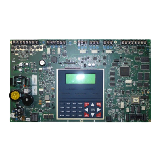
- Page 10 9050udlayo90.cdr MS-9050UD PN 52413:C 01/23/08...
- Page 11 Peripheral Devices ANN-S/PG ANN-I/O Printer Driver ANN-80 LED Driver Doc. #151417 Text Annunciator Doc. #151416 Doc. #52749 ANN-(R)LED LED Display ANN-RLY Doc. #53032 10 Form-C Relay Card Doc. #53033 ANN-BUS 4XTMF Municipal Box Transmitter SLC Loop Addressable Devices and SLC Wiring Doc.
-
Page 12: Product Description
Product Description Product Description SECTION 1 The MS-9050UD is a combination FACP (Fire Alarm Control Panel) and DACT (Digital Alarm Communicator/Transmitter) all on one circuit board. This compact, cost effective, intelligent addressable control panel has an extensive list of powerful features. The combination of Fire-Lite’s newer series devices and legacy 300 Series devices, along with the MS-9050UD FACP, offer the latest in fire protection technology. -
Page 13: Specifications
Product Description • History file with 500 event capacity • Advanced fire technology features: Automatic drift compensation Maintenance alert Detector sensitivity test capability (NFPA 72 compliant) Automatic device type-code verification Point trouble identification • Waterflow selection per module point • Alarm verification selection per detector point •... -
Page 14: Current Availability
Product Description Battery (Lead Acid Only) - J1 Maximum Charging Circuit: Normal Flat Charge - 27.6 VDC @ 1.2 amp Maximum Battery Charger Capacity: 18 Amp Hour, (FACP cabinet holds maximum of two 18 Amp Hour batteries) For greater than 18 Amp Hour up to 120 Amp Hour batteries, use the CHG-75 or CHG-120F Battery Charger and BB-55F Battery Box. -
Page 15: Controls And Indicators
Product Description 1.3 Controls and Indicators LCD Display The FACP uses an 80-character SYSTEM ALL NORMAL (4 lines X 20 characters) high viewing angle LCD display. The display includes a long life 10:00A 092105 LED backlight that remains illuminated. If AC power is lost and the system is not in alarm, the LED backlight will turn off to conserve batteries. -
Page 16: Digital Alarm Communicator/Transmitter
Product Description Output Circuits The following output circuits are available on the FACP: • Charger 24 VDC Battery Charger (up to 18 AH batteries) • NAC (Notification Appliance Circuits) Two NACs configurable for Style Y (Class B) or Style Z (Class A), are provided with various programmable features. -
Page 17: Components
Product Description 1.6 Components Main Circuit Board The main circuit board contains the system’s CPU, power supply, other primary components and wiring interface connectors. The 4XTMF option module plugs in and is mounted to the main circuit board. The circuit board is delivered mounted to a chassis in the MS-9050UD backbox (refer to circuit board illustration on page 10). -
Page 18: Optional Modules
Product Description Power Supervision Relay The UL listed End-of-Line power supervision relay is used to supervise the power to 4-wire smoke detectors and notification appliances. N-ELR Mounting Plate The N-ELR is a single End-of-Line resistor plate which is required for use in Canada. An ELR, which is supplied with each module and fire alarm control panel, is mounted to the ELR plate. -
Page 19: Battery Box
Product Description 1.8.4 Battery Box BB-26 The BB-26 battery box may be used to house up to two 26 AH batteries and the CHG-75 Battery Charger. The battery box, which is red and is provided with knockouts, was designed specifically to compliment mounting below the FACP. -
Page 20: Ann-Bus Devices
Product Description 1.9 ANN-BUS Devices WARNING! Disconnect all sources of power (AC and DC) before installing or removing any modules or wiring. A variety of optional devices can be connected to the FACP ANN-BUS communication circuit. Compatible devices include: • ANN-80 LCD Annunciator •... - Page 21 Product Description After calculating the total worst case current draw, Table 1.1 specifies the maximum distance the modules can be located from the FACP on a single wire run. The table ensures 6.0 volts of line drop maximum. In general, the wire length is limited by resistance, but for heavier wire gauges, capacitance is the limiting factor.
-
Page 22: Wiring Configuration
Product Description Wiring Distance Calculation Example: Suppose a system is configured with the following ANN-BUS modules: • 3 ANN-80 Remote Fire Annunciators • 1 ANN-S/PG Serial/Parallel Printer Interface Module • 1 ANN-I/O LED Driver Module The total worst case current is calculated as follows: ANN-80 Current Draw = 3 X 0.040 amps = 0.120 amps... -
Page 23: Powering Ann-Bus Devices From Auxiliary Power Supply
Product Description 1.9.1.3 Powering ANN-BUS Devices from Auxiliary Power Supply Figure 1.3 illustrates the powering of ANN-BUS devices from an auxiliary power supply such as the FCPS-24FS6/8, when the maximum number of ANN-BUS devices exceeds the ANN- BUS power requirements. Cut Ground Fault Detection jumper JP1 (FACP monitors for ground faults) ANN-BUS and power wiring are supervised and power-limited... -
Page 24: Remote Fire Annunciator
Product Description 1.9.3 ANN-80 Remote Fire Annunciator The ANN-80 Annunciator is a compact, 80 character, backlit LCD remote fire annunciator which mimics the FACP display. It also provides system status indicators for AC Power, Alarm, Trouble, Supervisory and Alarm Silenced conditions. Communication between the ANN-80 and FACP is accomplished over a two wire serial interface employing the ANN-BUS communication format. -
Page 25: Wiring Ann-80 To Facp
Product Description 1.9.3.5 Wiring ANN-80 to FACP The following steps can be used as a guide to wire the annunciator. Make certain all power has been removed from the FACP prior to annunciator installation. 1. Route wires from hole in backplate, through wiring channel and then to ANN-80 terminal block TB1 wiring channel wires... - Page 26 Product Description ANN-BUS and power wiring are supervised and power-limited ANN-80 FACP Figure 1.4 ANN-80 Wiring to FACP The following table shows the ANN-80 connections to the MS-9050UD. MS-9050UD (TB3) ANN-80 (TB1) Terminal 1 GND (-) Terminal 1 (-) Terminal 2 PWR (+) Terminal 2 (+) Terminal 3 A (ANN-BUS) Terminal 3 (A)
-
Page 27: Ann-S/Pg Serial/Parallel Interface Module
Product Description 1.9.4 ANN-S/PG Serial/Parallel Interface Module The ANN-S/PG Serial/Parallel Interface module allows the connection of a serial or parallel printer to the FACP for a real-time log of system events, detector status reports and event history. The module is provided with a plastic enclosure for surface mounting. Proceed with the installation as described in the following: 1. -
Page 28: Connecting Prn-6F Printer
Product Description 1.9.4.2.1 Connecting PRN-6F Printer Remote printers require a primary AC power source. If required for the fire alarm system configuration (for example, a Proprietary Fire Alarm System), a remote printer requires a secondary power source (battery backup). Since a secondary power source is not provided as a standard feature, a separate UL-listed Uninterruptible Power Supply (UPS) should be used. -
Page 29: Ann-I/O Led Driver Module
Product Description 1.9.5 ANN-I/O LED Driver Module The ANN-I/O is an LED driver module that can be used in a wide variety of applications, including as an interface with most customized graphic annunciators. The ANN-I/O can drive up to 40 LEDs. -
Page 30: Ann-I/O Connection To Facp
Product Description 1.9.5.3 ANN-I/O Connection to FACP The ANN-I/O connects to the FACP via the ANN-BUS as illustrated in Figure 1.2. After the ANN-I/O is connected to the panel, it must be added to the system via FACP programming. Refer to the section titled "Modules Installed" on page 106. ANN-I/O Module ANN-BUS and power wiring are supervised and power-limited... -
Page 31: Ann-I/O Module Led Wiring
Product Description 1.9.5.4 ANN-I/O Module LED Wiring There are four 12-pin connectors on the ANN-I/O module for connecting LEDs. Each set of 10 LEDs get their power from Pin 11 of the corresponding connector. Internal resistors are sized so that there is approximately 10 mA of current for each LED. No series resistors are required. LED outputs can be mapped to output circuits. -
Page 32: Ann-Led Annunciator Module
Product Description 1.9.6 ANN-LED Annunciator Module The ANN-LED and ANN-RLED annunciator modules provide LED annunciation of general system faults and input zones/points when used with a compatible FACP. The ANN-LED module provides alarm (red), trouble (yellow) and supervisory (yellow) indication for up to ten input zones or addressable points. -
Page 33: Ann-Led Connection To Facp
Product Description 1.9.6.3 ANN-LED Connection to FACP Figure 1.5 illustrates the ANN-LED board showing locations of screw terminals for connection to the FACP and the DIP switches for selecting the ANN-BUS ID number. Ground wire from mounting screw to FACP Earth Ground stud is required for Canadian applications when annunciator is mounted remotely (refer to "ANN-LED Annunciator... -
Page 34: Ann-Rly Relay Module
Product Description 1.9.7 ANN-RLY Relay Module The ANN-RLY relay module provides 10 programmable Form-C relays when used with a compatible FACP. 1.9.7.1 ANN-RLY Board Layout Figure 1.6 illustrates the ANN-RLY board showing locations of screw terminals for connection to the FACP and the DIP switches for selecting the ANN-BUS ID number. ANN-BUS (ID#) Address DIP switch ANN-BUS Connector... -
Page 35: Ann-Rly Connection To Facp
Product Description 1.9.7.4 ANN-RLY Connection to FACP Figure 1.7 illustrates the ANN-RLY board showing locations of screw terminals for connection to the FACP and the DIP switches for selecting the ANN-BUS ID number. ANN-RLY ANN-BUS and power wiring are +24 VDC supervised and power-limited -24 VDC ANN-BUS... -
Page 36: Telephone Requirements And Warnings
Product Description 1.11 Telephone Requirements and Warnings 1.11.1 Telephone Circuitry AC Ringer Equivalence Number (REN) = 03B DC Ringer Equivalence Number (REN) = 0.0B AC Impedance: 10.0 Mega Ohm Complies with FCC Part 68 Mates with RJ31X Male Connector Supervision Threshold: loss of phone line voltage for 2 minutes The REN is used to determine the quantity of devices which may be connected to the telephone line. -
Page 37: Telephone Company Rights And Warnings
Product Description 1.11.3 Telephone Company Rights and Warnings The telephone company, under certain circumstances, may temporarily discontinue services and/or make changes in its facilities, services, equipment or procedures which may affect the operation of this control panel. However, the telephone company is required to give advance notice of such changes or interruptions. -
Page 38: For Canadian Applications
Product Description 1.11.4 For Canadian Applications The following is excerpted from CP-01 Issue 5: NOTICE: The Industry Canada (IC) label identifies certified equipment. This certification means that the equipment meets certain telecommunications network protective, operational and safety requirements as prescribed in the appropriate Terminal Equipment Technical Requirements docu- ment(s). -
Page 39: Installation
Installation Installation SECTION 2 The cabinet may be either semi-flush or surface mounted. The cabinet mounts using two key slots and two 0.250” (6.35 mm) diameter holes located in the backbox. The key slots are located at the top of the backbox and the two securing holes at the bottom. Carefully unpack the system and check for shipping damage. -
Page 40: Mounting Chassis/Transformer/Main Circuit Board
Installation 2.2 Mounting Chassis/Transformer/Main Circuit Board One transformer is supplied standard with the control panel. Install the transformer and chassis in the location indicated in the following illustration. 6. When the location is dry and free of construction dust, install the chassis/transformer/circuit board assembly. - Page 41 Installation Semi-Flush Mounting Do not recess box more than 3.875” into wall to avoid covering venting Hinge Slot for optional holes on top of box. Dress Panel Mounting slots for optional Trim Ring Semi-Flush mounting hole Hinge Slot for optional Dress Panel Figure 2.3 FACP Cabinet Mounting MS-9050UD PN 52413:C 01/23/08...
- Page 42 Installation Figure 2.4 FACP Cabinet Dimensions MS-9050UD PN 52413:C 01/23/08...
-
Page 43: Power
Installation 2.3 Power WARNING: Several different sources of power can be connected to this panel. Disconnect all sources of power before servicing. The panel and associated equipment may be damaged by removing and/or inserting cards, modules or interconnecting cables while this unit is energized. 2.3.1 AC Power and Earth Ground Connection Primary power required for the FACP is 120 VAC, 60 Hz, 3.0 amps for the MS-9050UD. -
Page 44: Relays
Installation 2.4 Relays The FACP provides two programmable Form-C relays and one fixed fail-safe Form-C trouble relay, all with contacts rated for 2.0 amps @ 30 VDC (resistive) or 0.5 amps @ 30 VAC (resistive). Note that relay connections must be power-limited. Refer to UL Power-limited wiring requirements. -
Page 45: Configuring Nacs
Installation 2.5.1 Configuring NACs The Notification Appliance Circuits are configured for Style Y (Class B) or Style Z (Class A) by properly wiring the NAC devices to TB1 on the main circuit board as illustrated below. Style Y (Class B) Notification Appliance Style Z (Class A) Notification Appliance NAC 1 NAC 2... -
Page 46: Ul Power-Limited Wiring Requirements
Installation 2.6 UL Power-limited Wiring Requirements Power-limited and nonpower-limited circuit wiring must remain separated in the cabinet. All power-limited circuit wiring must remain at least 0.25” (6.35 mm) away from any nonpower- limited circuit wiring and nonpower-limited circuit wiring must enter and exit the cabinet through different knockouts and/or conduits. -
Page 47: Digital Communicator
Installation 2.7 Digital Communicator Two independent telephone lines can be connected to the control panel. Telephone line control/ command is made possible via double line seizure as well as usage of an RJ31X style interconnec- tion. Note that it is critical that the panel's digital communicator be located as the first device on the incoming telephone circuit to properly function. -
Page 48: Optional Modules/Accessories Installation
Installation 2.8 Optional Modules/Accessories Installation WARNING! Disconnect all sources of power (AC and DC) before installing or removing any modules or wiring. 2.8.1 4XTMF Transmitter Module Installation The 4XTMF provides a supervised output for a local energy municipal box transmitter in addition to alarm and trouble reverse polarity. - Page 49 Installation Before installing the module, place the disconnect switch to the right (disconnect) position to prevent accidental activation of the municipal box. Note that a Disconnect LED will illuminate after the module is installed in the MS-9050UD. In addition, the System Trouble LED will turn on to indicate the Disconnect condition.
- Page 50 Installation The following steps must be followed when installing the 4XTMF module: 1. Remove all power (Primary and Secondary) from the FACP before installing 4XTMF 2. Cut jumper JP28 on the main circuit board to allow the control panel to supervise the 4XTMF module 3.
-
Page 51: Programming
Programming Programming SECTION 3 NOTICE TO USERS, INSTALLERS, AUTHORITIES HAVING JURISDICTION AND OTHER INVOLVED PARTIES This product incorporates field-programmable software. In order for the product to comply with the requirements in the Stan- dard for Control Units and Accessories for Fire Alarm Systems, UL 864, certain programming features or options must be lim- ited to specific values or not used at all as indicated below: Program feature Permitted in... -
Page 52: User Programming
Programming 3.2 User Programming The MS-9050UD is completely field programmable and requires no special software skills. While ! ! ! programming the MS-9050UD, the fire protection capabilities of the control panel are enabled. Site-specific programming may be accomplished in three ways: •... -
Page 53: Initial Power-Up
Programming User Programming Levels There are two user programming levels: • User Master Program Level 1 is used for programming panel specific data relating to device types, zoning, messages, control panel functions, etc. • User Maintenance Program Level 2 is used by a qualified operator to access features such as Disable/Enable, View and Clear History, Walktest and System Time Change. - Page 54 Programming To access user Programming mode, press the Enter or Mode key. The LCD will display the following: 1=READ STATUS MODE 2=PROGRAMMING MODE 3=MANUAL DIAL MODE 4=REMOTE DOWNLOAD To enter the user Programming mode, press 2. The display will read as follows: PROGRAMMING ENTER PASSWORD *****...
-
Page 55: Master Programming Level
Programming 3.6 Master Programming Level When the Master Program Level password is entered, the control panel will enter user Programming mode. In this mode, the piezo sounder remains off, the trouble relay is activated and the system Trouble LED flashes until Programming mode is exited. The following display will appear: PROGRAMMING 1=AUTOPROGRAM... -
Page 56: Autoprogram
Programming 3.6.1 Autoprogram Pressing 1 while viewing Programming Screen #1, will select the Autoprogram option, which prompts the control panel to poll all devices installed on the SLC loop. The primary purpose of autoprogramming is to allow the installer a fast and easy way to bring the system on-line as quickly as possible. -
Page 57: Point Program
Programming 3.6.2 Point Program The Point Program option allows the programmer to add a new addressable device to an SLC loop, delete an existing device from a loop or change the programming for an existing device. Pressing 2, while viewing Programming Screen #1, will select the Point Program option and display the following screen: PROGRAMMING POINT PROGRAM... -
Page 58: Delete Detector
Programming When the type has been selected, the following screen will be displayed: ADD DETECTOR DETECTOR# IS ADDED The programmer can continue adding detectors by pressing the ESC key which will return the display to the Add Detector Screen. 3.6.2.1.2 Delete Detector Pressing 2 in the Detector Screen will display the Delete Detector Screen which allows the DETECTOR programmer to delete a specific detector:... - Page 59 Programming When the last digit is keyed-in, if the selected address has not been added to programming, a screen showing information about a device that is installed with a lower address, closest to the selected address, will be displayed. If no detectors have been installed on the loop, the following will be displayed: NO DETECTOR INSTALLED Edit Detector Screen #1...
- Page 60 Programming The following examples show the editing of a photoelectric smoke detector with address 017, located on the SLC loop: EDIT DETECTOR 1D017 1=ENABLED 2=TYPE SMOKE(PHOTO) 3=VERIFICATION Edit Detector Screen #2 EDIT DETECTOR 1D017 1=WALKTEST 2=PAS 3=PRE-SIGNAL Edit Detector Screen #3 EDIT DETECTOR 1D017 1=ZONE ASSIGNMENT 00 ** ** ** **...
- Page 61 Programming Type To select the type of detector being programmed, press the 2 key while viewing the Edit Detector Screen #2. This will cause the control panel to display the following Detector Type Screen: DETECTOR TYPE 1=SMOKE(PHOTO) EDIT DETECTOR 2=USER-DEFINED-1 1=ENABLED 3=SMOKE (ION) 2=TYPE...
- Page 62 Programming The PAS (Positive Alarm Sequence) option will program the detector to delay panel activation (including alarm relay and communicator) for a period of 15 seconds plus a programmable time of up to 3 minutes. Zone 17, however, will activate immediately and may be used to connect a signaling device to indicate PAS activation (do not use a Notification Appliance Circuit for this purpose).
- Page 63 Programming With the preceding program settings, when the detector with address 005 is activated, zone Z18 will cause its associated control module to activate immediately, sounding the connected signaling device to indicate the Pre-signal condition. Following the Pre-signal delay time, zone Z001 will cause its associated control module to activate and the control panel will initiate an alarm condition.
- Page 64 Programming Pressing 1 while viewing the Noun/Adjective Screen will cause the following screen(s) to be 1=STANDARD ADJECTIVE displayed. Note that the keyboard down arrow key must be pressed to see all the Adjective 2=STANDARD NOUN screens. Press the number corresponding to the adjective that is to be used as a descriptor for 3=CUSTOM ADJECTIVE the location of the detector currently being programmed.
- Page 65 Programming Pressing 2 while viewing the Noun/Adjective Screen will cause the following screen(s) to be 1=STANDARD ADJECTIVE displayed. Note that the keyboard down arrow key must be pressed to see all the Noun screens. 2=STANDARD NOUN Press the number corresponding to the noun that is to be used as a descriptor for the location of 3=CUSTOM ADJECTIVE the detector currently being programmed.
- Page 66 Programming Pressing 3 or 4 while viewing the Noun/Adjective Screen will display screens similar to the previous Adjective and Noun Screens. The new screens will list custom Adjectives and Nouns which have been programmed into the control panel by the user utilizing the PK-CD programming kit.
-
Page 67: Module Programming
Programming As an example, the user could quickly enter ‘FLR_3_ROOM_305’ as follows: 1. The cursor is on the first letter of the Adjective field. Press the zero key twice to display FLR_3 2. With the cursor on the first letter of the Noun field, press the zero key twice to recall the display ROOM_304. -
Page 68: Delete Module
Programming Pressing 1 for Control Module or 2 for Monitor Module will cause the following screen to be displayed: ADD MODULE MODULE# IS ADDED Add Module Screen #3 The programmer can continue adding modules by pressing the ESC or left arrow key which will return the display to the Add Module Screen #1. - Page 69 Programming When the last digit is keyed-in, if the selected address has not been added to programming, a screen showing information about a device that is installed with a lower address, closest to the selected address, will be displayed. If no modules are installed on the loop, the following screen will be displayed: NO MODULE INSTALLED...
-
Page 70
Programming If the selected address corresponds to a control module, a screen displaying information about the control module with the selected address will be displayed as shown in "Edit Module Screen for Control Modules" on page 77. See Page If the selected address corresponds to a monitor module, a screen displaying information about the module with the selected address will be displayed as illustrated in the following: NORMAL MONITOR
... - Page 71 Programming Enable/Disable Module To Enable or Disable the monitor module, press the 1 key while viewing the Edit Module Screen #2. Each press of the key will toggle the screen between Enabled Yes and Enabled No. If Enabled No is selected, the module will not be polled by the control panel, preventing the module from reporting alarms and troubles to the panel.
- Page 72 Programming Monitor module type selection will affect the function of the point as follows: Table 3.1 Monitor Types Monitor Type Action When Activated Pull-Station Fire Alarm User-Defined-1 Fire Alarm Waterflow Fire Alarm Delayed (uses waterflow delay) User-Defined-2 Fire Alarm Delayed (uses waterflow delay) Monitor Fire Alarm User-Defined-3...
- Page 73 Programming Pre-signal To enable the Pre-signal feature, press 1 while viewing Edit Monitor Screen #3 until the display EDIT MONITOR reads Pre-signal Yes. Each press of the 1 key will cause the display to toggle between Pre- 1=PRE-SIGNAL signal Yes and Pre-signal No. Refer to "Presignal" on page 155 for additional information. Walktest Edit Monitor Screen #3 The Walktest feature allows one person to test the system devices without the necessity of...
- Page 74 Programming Pressing 1 while viewing the Noun/Adjective Screen will cause the following screen(s) to be 1=STANDARD ADJECTIVE displayed. Note that the keyboard down arrow key must be pressed to see all the Adjective 2=STANDARD NOUN 3=CUSTOM ADJECTIVE screens. Press the number corresponding to the adjective that is to be used as a descriptor for 4=CUSTOM NOUN the location of the monitor module currently being programmed.
- Page 75 Programming Pressing 2 while viewing the Noun/Adjective Screen will cause the following screen(s) to be 1=STANDARD ADJECTIVE displayed. Note that the keyboard down arrow key must be pressed to see all the Noun screens. 2=STANDARD NOUN 3=CUSTOM ADJECTIVE Press the number corresponding to the noun that is to be used as a descriptor for the location of 4=CUSTOM NOUN the monitor module currently being programmed.
- Page 76 Programming Description The Description selection allows the programmer to enter additional information about the monitor module currently being programmed. This information will be displayed as part of the device label on the LCD display. Pressing 2 while viewing Edit Monitor Screen #5 will cause the following screen to be displayed: EDIT MONITOR 1=NOUN/ADJECTIVE...
-
Page 77: Edit Module Screen For Control Modules
Programming As an example, the user could quickly enter ‘FLR_3_ROOM 305’ as follows: 1. The cursor is on the first letter of the Adjective field. Press the zero key twice to display FLR_3 2. With the cursor on the first letter of the Noun field, press the zero key twice to recall the display ROOM_304. - Page 78 Programming To change the programming for the displayed module, press the keyboard down arrow key to view the following Edit Control screens: EDIT CONTROL 1=ENABLED 2=TYPE CONTROL 3=SILENCEABLE Edit Control Screen #2 EDIT CONTROL 1=WALKTEST 2=ZONE ASSIGNMENT 00 ** ** ** ** Edit Control Screen #3 EDIT CONTROL 1=NOUN/ADJECTIVE...
- Page 79 Programming Type To select the type of control module being programmed, press the 2 key while viewing the Edit Control Screen #2. This will cause the control panel to display the following Control Type Screens: CONTROL TYPE EDIT CONTROL 1=BLANK 1=ENABLED 2=TYPE 2=BELL-CIRCUIT...
- Page 80 Programming Silenceable The Silenceable selection allows the programmer to select whether output devices connected to the control module can be silenced, either by pressing the Alarm Silence key or by enabling Autosilence. Pressing the 3 key while viewing Edit Control Screen #2 will enable the Silenceable feature causing the display to read Silenceable Yes.
- Page 81 Programming Pressing 1 while viewing the Noun/Adjective Screen will cause the following screen(s) to be 1=STANDARD ADJECTIVE displayed. Note that the keyboard down arrow key must be pressed to see all the Adjective 2=STANDARD NOUN 3=CUSTOM ADJECTIVE screens. Press the number corresponding to the adjective that is to be used as a descriptor for 4=CUSTOM NOUN the location of the control module currently being programmed.
- Page 82 Programming Pressing 2 while viewing the Noun/Adjective Screen will cause the following screen(s) to be 1=STANDARD ADJECTIVE displayed. Note that the keyboard down arrow key must be pressed to see all the Noun screens. 2=STANDARD NOUN 3=CUSTOM ADJECTIVE Press the number corresponding to the noun that is to be used as a descriptor for the location of 4=CUSTOM NOUN the control module currently being programmed.
- Page 83 Programming Description The Description selection allows the programmer to enter additional information about the control module currently being programmed. This information will be displayed as part of the device label on the display. Pressing 2 while viewing Edit Control Screen #4 will cause the following screen to be displayed: EDIT CONTROL DESCRIPTION...
-
Page 84: Zone Setup
Programming 3.6.3 Zone Setup Pressing 3 while viewing Programming Screen #2 will access the Zone Setup screens as illustrated below: ZONE SETUP PROGRAMMING 1=ENABLE 1=AUTOPROGRAM 2=DISABLE 2=POINT PROGRAM 3=ZONE 17 18 19 3=ZONE SETUP Programming Screen #2 Zone Setup Screen #1 ZONE SETUP 1=ZONES INSTALLED 2=ZONES ENABLED... -
Page 85: Disable
Programming 3.6.3.2 Disable Pressing 2 for Disable, while viewing Zone Setup Screen #1, displays the following: ZONE TO DISABLE ZONE SETUP 1=ENABLE 2=DISABLE Disable Screen 3=ZONE 17 18 19 Zone Setup Screen #1 This screen allows the programmer to disable zones, one at a time. A flashing cursor appears next to the Z, prompting the programmer to enter a two digit zone number (01 - 19). -
Page 86: Zones Installed
Programming 3.6.3.4 Zones Installed Pressing 1 for Zones Installed, while viewing Zone Setup Screen #2, will display a screen similar to the following: ZONES INSTALLED 00 01 02 03 04 05 ZONE SETUP 1=ZONES INSTALLED 2=ZONES ENABLED 3=ZONES DISABLED Zone Setup Screen #2 Zones Installed Screen This display will show all of the zones that have been programmed into the control panel. - Page 87 Programming The Zones Installed screen will show the system zones (default and user programmed) and their associated types. Note that an up and/or down arrow will appear in the upper right corner of the display, indicating that additional screens of zone information exists. Press the up or down arrow keys to view zones Z00 through Z19.
-
Page 88: Zones Available
Programming 3.6.3.8 Zones Available Pressing 2 while viewing Zone Setup Screen #3 will display the following screen: ZONES AVAILABLE 01 02 03 04 05 06 07 ZONE SETUP 08 09 10 11 12 13 14 1=ZONE TYPES 2=ZONES AVAILABLE 15 16 17 18 19 3=FUTURE Zone Setup Screen #3 The display will show all of the zones that are still available for programming. -
Page 89: System Setup
Programming 3.6.5 System Setup System Setup allows the programmer to configure the following control panel features: • Trouble Reminder: This feature, when enabled, provides an audible reminder that an alarm or trouble still exists on the FACP after the control panel has been silenced. The control panel piezo sounder will pulse once every 15 seconds during an alarm and every two minutes during a trouble condition, after the Alarm Silence or Acknowledge key is pressed. -
Page 90: Trouble Reminder
Programming 3.6.5.1 Trouble Reminder The Trouble Reminder features causes the control panel piezo to sound a reminder ‘beep’ for alarms and troubles, after the panel has been silenced. Refer to "System Setup" on page 89, for a detailed description of this feature. Pressing 1 while viewing System Setup Screen #1 will cause the display to toggle to Trouble Rem On, which enables this feature. -
Page 91: Time-Date
Programming These screens allow the programmer to enter a two line custom banner. A flashing cursor will appear in the bottom left corner of each display. A maximum of 20 characters (including spaces) can be entered into each screen for a total of two lines with 40 characters. After entering up to 20 characters in the first screen, press Enter to view the second screen. -
Page 92: Date
Programming 3.6.5.3.2 Date To change the date, press 2 while viewing the Time-Date Screen. The following screen will be displayed: ENTER DATE MONTH DAY YEAR 09-07-2005 Date Screen A flashing cursor is located toward the top left of the display. Below the cursor is the current date. -
Page 93: Timers
Programming Pressing 3 while viewing Daylight Savings Screen #1 will display two sub-screens which allow the programmer to select the week of the month that daylight savings time will begin. In the first sub-screen, pressing 1 will select the first week, 2 will select the second week and 3 will select the third week, while in the second sub-screen, pressing 1 will select the fourth week and 2 will select the last week of the selected month. -
Page 94: Presignal Delay
Programming 3.6.5.4.2 Pre-signal Delay The factory default setting for Pre-signal delay is 000 for no delay. To select a Pre-signal delay of 001 to 180 seconds for all devices programmed for Pre-signal, press 2 while viewing Timer Screen #1. The following screen will be displayed: PRESIGNAL DELAY RANGE 0-180 SECONDS Pre-signal Delay Screen... -
Page 95: Ac Loss Delay
Programming 3.6.5.4.4 AC Loss Delay The reporting of a loss of AC power to a central station can be delayed by programming the length of the desired delay. The factory default setting is 2 hours. Press 1 while viewing Timer Screen #2 to display the following: AC LOSS DELAY 1=NO DELAY... -
Page 96: Enabled
Programming The following screens will be displayed for each selection: NAC # 1=ENABLED 2=TYPE BELL 3=SILENCEABLE NAC Screen #1 NAC # 1=AUTO SILENCE 2=CODING STEADY NAC Screen #2 NAC # 1=ZONE 00 ** ** ** ** 2=SIL INHIBITED NAC Screen #3 NAC # 1=SYNC TYPE NAC Screen #4... -
Page 97: Type
Programming 3.6.5.5.2 Type The main circuit board NAC type can be programmed by pressing 2 while viewing NAC Screen #1. The following screen will be displayed. Press the down arrow key to view additional screens: NAC TYPE NAC # 1=ENABLED 1=BELL 2=TYPE 2=HORN... -
Page 98: Auto Silence
Programming 3.6.5.5.4 Auto Silence The Auto Silence feature, when enabled, automatically silences all main circuit board silenceable notification appliances after a programmed length of time. To enable this feature and program the time delay before Auto Silence activation, press 1 while viewing NAC Screen #2. - Page 99 Programming The programmer can select the notification appliance output by pressing the number corresponding to the desired output. The coding selections are: • Steady - a continuous output with no coding • March Time - 120 ppm (pulse-per-minute) output • California - 10 seconds on and 5 seconds off •...
-
Page 100: Zone
Programming 3.6.5.5.6 Zone A maximum of five zones can be programmed to each main circuit board NAC. Pressing 1 while viewing NAC Screen #3 displays the following screen: ZONE ASSIGNMENT Z00 Z** Z** Z** Z** NAC # 1=ZONE 00 00 00 00 00 Zone Screen 2=SIL INHIBITED NO NAC Screen #3... -
Page 101: Relays
Programming 3.6.5.6 Relays Pressing 3 while viewing System Setup Screen #2 will allow the programmer to configure two main circuit board Form-C relays from the following screen: RELAYS 1=RELAY 1 SYSTEM SETUP 2=RELAY 2 1=TIMERS 3=RELAY 3 2=NAC 3=RELAYS System Setup Screen #2 Relays Selection Screen To program Relay 1 or Relay 3, press the number corresponding to the selected relay. -
Page 102: Canadian Option
Programming 3.6.5.7 Canadian Option Pressing 1 while viewing System Setup Screen #3 will configure the FACP to comply with Canadian requirements. The display will change to Canadian Opt. On. Each press of the 1 key will cause the display to toggle between Canadian Opt. On and Canadian Opt. Off. The factory default setting is Canadian Opt. -
Page 103: History
Programming 3.6.7 History The History option allows an authorized user to view or erase events which have occurred in the control panel. Pressing 1 while viewing Programming Screen #3 will display the History options as shown in the following display: HISTORY PROGRAMMING 1=VIEW EVENTS... -
Page 104: Walktest
Programming 3.6.8 Walktest Walktest allows an individual to test the fire alarm system without the necessity to reset the control panel after each device activation. Pressing 2 while viewing the Programming Screen #3 will cause the following Walktest options to be displayed: WALKTEST PROGRAMMING 1=HISTORY... -
Page 105: Option Modules
Programming Pressing 3 for View Summary while viewing the Unit In Walktest screen will display a new screen which will show a total of the tested detectors, tested modules, untested detectors and untested modules for the current walktest session. The user can perform a one-person walktest by activating devices throughout the system. As each device is activated, the information about the activated device is store in the Walktest Log. -
Page 106: Ann-Bus
Programming 3.6.9.1 ANN-BUS Pressing 1 while viewing the Option Modules screen will cause the control panel to display the following screens. ANN-BUS 1=ENABLED 2=MODULES INSTALLED 3=AUTO-CONFIGURE ANN-BUS Screen #1 ANN-BUS 1=ANN-S/PG OPTIONS 2=ANN-80 OPTIONS ANN-BUS Screen #2 A printer module and LCD annunciator module can be programmed into the MS-9050UD system. - Page 107 Programming Pressing 1 for Type will display the following screens: ANN-BUS MODULE TYPE 1=NOT INSTALLED 2=ANN-80 MODULE 3=ANN-I/O MODULE Module Type Screen #1 ANN-BUS MODULE TYPE 1=ANN-S/PG MODULE 2=ANN-LED MODULE 3=ANN-RLY MODULE Module Type Screen #2 Press the number corresponding to the module type that is installed with the selected address. Note: If the module type selected is the ANN-80 or ANN-S/PG or if Not Installed is selected, the ANN-BUS Address Screen shown on the previous page will be displayed following the module selection.
- Page 108 Programming Pressing 1 while viewing the ANN-I/O Address Screen will program the annunciator module to annunciate either Point (addressable device address) information or Zone information. Each press of the 1 key will toggle the display between Zone and Point. Pressing 2 while viewing the ANN-I/O Address Screen will select the Point range to be annunciated (refer to the tables in "ANN-I/O Zone Option"...
- Page 109 Programming ANN-I/O Point Option If Point is selected as the module option, the first ten LEDs on the first ANN-I/O module will display the system status information. The remaining 30 LEDs on the first module and 20 LEDs on the second module will display the active/alarm status of each point in the Point Range programmed for that particular module.
- Page 110 Programming ANN-LED Options Screen Pressing 2 for Module Options while viewing ANN-BUS Address Screen when the ANN-LED option is selected, will display the following screen: ANN-LED ADDR # PROGRAMMING ZONES 00-09 1=ANN-RLY OPTIONS 2=ANN-LED OPTIONS ALARM, TRBL, SUPV ANN-BUS Screen #3 ANN-LED Address Screen #1 ANN-LED ADDR # 1=POINT/ZONE...
- Page 111 Programming ANN-RLED Zone Option - Alarm Only If Zone is selected as the module option, and the module is programmed to annunciate alarms only, the first ten LEDs on the ANN-RLED module will display the system status information. The next 20 LEDs on the module will display the active/alarm status of each zone. The last 10 LEDs are not used.
- Page 112 Programming ANN-LED Zone Option - Alarm, Trouble and Supervisory If Zone is selected as the module option, and the module is programmed to annunciate alarms, troubles and supervisories, the first ten LEDs on the first ANN-LED module will display the system status information.
- Page 113 Programming ANN-RLED Point Option - Alarm Only If Point is selected as the module option and the module is programmed to annunciate alarms only, the first ten LEDs on the first ANN-RLED module will display the system status information. The remaining 30 LEDs on the first module and LEDs 11 - 30 on the second module will display the active/alarm status of each point in the Point Range programmed for that particular module.
- Page 114 Programming ANN-LED Point Option - Alarm, Trouble and Supervisory If Point is selected as the module option, and the module is programmed to annunciate alarms, troubles and supervisories, the first ten LEDs on the first ANN-LED module will display the system status information.
- Page 115 Programming ANN-RLY Options Screen Pressing 2 for Module Options while viewing ANN-BUS Address Screen when the ANN-RLY option is selected, will cause the following screen to be displayed: ANN-RLY - ADDR. # 1=RELAY 1 ZONE 00 2=RELAY 2 ZONE 01 3=RELAY 3 ZONE 02 ANN-RLY Options Screen...
-
Page 116: Auto-Configure
Programming 3.6.9.1.3 Auto-Configure The ANN-BUS Auto-Configure features allows the programmer to quickly bring all installed ANN-BUS modules online. The software will search for all ANN-BUS modules and automatically program the device type and address into the system. The ANN-BUS must be enabled for the Auto-Configure feature to work. -
Page 117: Options Screen
Programming If the Parallel Port option is selected, the user has the option to supervise the printer and select an offline timer for the supervision by pressing 2 for Printer Supervision while viewing Print Options screen #1. Each press of the 2 key will cause the display to toggle between Printer Supv NO for no supervision and Printer Supv YES for printer supervision. -
Page 118: Onboard Dact
Programming The Silence Button Enable (SIL BTN ENABLE) option allows the programmer to select whether the Silence button on any installed ANN-80 annunciator will function normally or always be ignored. Pressing 1 while viewing the ANN-80 Options Screen #2 causes the display to toggle between Sil Btn Enable Yes (Silence button functions normally) and Sil Btn Enable No (Silence button never functions). -
Page 119: Secondary Phone
Programming To select the type, press 1 while viewing the Primary Phone Line screen. The following screen will be displayed: PHONE LINE 1=TOUCHTONE 2=ROTARY Primary Phone Type Screen Press 1 to select Touchtone dialing or 2 to select Rotary dialing. 3.6.9.2.3 Secondary Phone ON BOARD DACT Press 3 while viewing On Board DACT Screen #1 to program the type of secondary phone line... -
Page 120: Central Station
Programming 3.6.9.2.3.1 Ring Count The ring count designates the number of rings allowed on the phone line prior to answering an ON BOARD DACT 1=RING COUNT incoming call from a service terminal. The factory default is 0 which means the control panel 2=CENTRAL STATION will not answer any incoming calls. -
Page 121: Trouble Call Limit (Dialer Runaway Prevention)
Programming 3.6.9.2.4.2 Backup Reporting The DACT can be programmed to transmit reports to primary and/or secondary central station phone numbers as a backup. Press 2 while viewing Central Station Screen #1 to display the following screen: BACKUP REPORTING 1=BACKUP ONLY 2=BOTH 3=FIRST AVAILABLE Backup Reporting Screen... - Page 122 Programming 3.6.9.2.5.1 Central Station Primary and Secondary Phone Numbers Pressing 1 for Primary or 2 for Secondary will display the following screens. Note that the following information must be entered for both the Primary and Secondary Central Station Phone Numbers. CENTRAL STATION # 1=TEST TIME INT CENTRAL STATION...
- Page 123 Programming Test Time Interval Pressing 1 while viewing Primary/Secondary Screen #1 will cause the following screens to be displayed: TEST TIME INTERVAL 1=24 HOURS CENTRAL STATION 2=12 HOURS 1=TEST TIME INT 3=8 HOURS 2=ACCOUNT CODE 3=24HR TST TIME Test Time Interval Screen #1 Primary/Secondary Screen #1 TEST TIME INTERVAL 1=6 HOURS...
- Page 124 Programming 24 Hour Test Time Pressing 3 while viewing Primary/Secondary Screen #1 will cause the following screen to be displayed: 24 HOUR TEST TIME RANGE 0000-2359 CENTRAL STATION 1=TEST TIME INT 2=ACCOUNT CODE 3=24HR TST TIME 24 Hour Test Time Screen Primary/Secondary Screen #1 Use the 24 Hour Test Time screen to program the time that the DACT will transmit the 24 Hour Test to the Central Station.
- Page 125 Programming Communication Format Pressing 1 while viewing Primary/Secondary Screen #3 will cause the following screens to be displayed: COMM FORMAT 1=ADEMCO EXPRESS 4P1 CENTRAL STATION 2=ADEMCO EXPRESS 4P2 1=COMM FORMAT 3=3P1S C18 A23 Comm Format Screen #1 Primary/Secondary Screen #3 COMM FORMAT 1=3P1E C18 A23 2=3P1S C19 A14...
- Page 126 Programming The Communication Format is determined by the type of receiver that the DACT is transmitting to. Consult your Central Station for proper selection or consult our factory representatives. For any format chosen, the control panel automatically programs all of the event codes. Select the Communication Format by pressing the corresponding number key while viewing the appropriate Comm Format screen.
- Page 127 Programming 3+1, 4+1 Express and 4+1 Standard The information shown in Table 3.3 is automatically programmed for the Central Station phone number Event Codes when any of these Formats are selected. Enter 0 for an Event Code Setting to disable the report. Table 3.3 Event Codes Event Description Event Code Settings...
- Page 128 Programming Table 3.3 Event Codes (continued) MON-USER-DEF-14 TROUBLE MON POINT_FAULT code will always be transmitted MON-USER-DEF-15 POINT_FAULT code will always be transmitted PROCESS MON MON-USER-DEF-16 PROCMON AR MON-USER-DEF-17 not used not used POINT_FAULT POINT_DISABLE AC_FAIL DRILL SLC 1 OPEN FAULT SLC 1 SHORT FAULT GROUND FAULT LOW BATTERY...
- Page 129 Programming 4+2 Standard, 4+2 Express, 3 + 1, 4 + 1 and 4+2 Expanded Formats The information shown in Table 3.4 is automatically programmed for the Central Station phone number Event Codes when any of these Formats are selected. Enter 00 for an Event Code Setting to disable the report.
- Page 130 Programming Table 3.4 Event Codes (continued) POWER MON MON-USER-DEF-14 TROUBLE MON POINT_FAULT code will always be transmitted MON-USER-DEF-15 POINT_FAULT code will always be transmitted PROCESS MON MON-USER-DEF-16 PROCMON AR MON-USER-DEF-17 not used not used POINT_FAULT POINT_DISABLE AC_FAIL DRILL SLC 1 OPEN FAULT SLC 1 SHORT FAULT GROUND FAULT LOW BATTERY...
- Page 131 Programming Ademco Contact ID Format The information shown in Table 3.5 is automatically programmed for the Central Station phone number Event Codes when Ademco Contact ID Format is selected. Enter 000 for an Event Code Setting to disable the report. Table 3.5 Event Codes Event Description Event Code Settings...
- Page 132 Programming Table 3.5 Event Codes (continued) POWER MON MON-USER-DEF-14 TROUBLE MON POINT_FAULT code will always be transmitted MON-USER-DEF-15 POINT_FAULT code will always be transmitted PROCESS MON MON-USER-DEF-16 PROCMON AR MON-USER-DEF-17 not used not used POINT_FAULT POINT_DISABLE AC_FAIL DRILL SLC 1 OPEN FAULT SLC 1 SHORT FAULT GROUND FAULT LOW BATTERY...
-
Page 133: Manual Dial Mode
Programming Report Style Pressing 3 while viewing Central Station Screen #2 will cause the Report Style display to toggle between Point and Zone. Setting the Report Style to Point will program the DACT to report individual point status to the Central Station. The control panel is capable of monitoring a total of 50 addressable devices. -
Page 134: Password Change
Programming 3.6.10 Password Change The factory set passwords, which have been programmed into the control panel, can be changed by selecting the Password Change option. Pressing 1 while viewing Programming Screen #4 will cause the following screen to be displayed: PASSWORD CHANGE 1=MASTER PROGRAMMING... -
Page 135: Clear Program
Programming 3.6.11 Clear Program Pressing 2 while viewing Programming Screen #4, will select the Clear Program option. This will cause the LCD to display the following screen: CLEAR PROGRAM 1=WHOLE SYSTEM 2=ALL POINTS PROGRAMMING 1=PASSWORD CHANGE 2=CLEAR PROGRAM 3=PROGRAM CHECK Clear Program Screen #1 Programming Screen #4 Pressing 1, for Whole System while viewing the Clear Program Screen #1, will clear all general... -
Page 136: Program Check
Programming 3.6.12 Program Check The Program Check feature allows the programmer to view the zones which have been programmed to the Notification Appliance Circuits on the control panel but have not been programmed to Initiating Devices as well as other circuits with no input or output correlations. Pressing 3 while viewing Programming Screen #4 will cause the following screen to be displayed: PROGRAMMING 1=PASSWORD CHANGE... - Page 137 Programming Pressing 2 while viewing the Program Check screen will display a screen similar to the following: ZONES NO INPUT 05 07 09 10 11 1M001 The Zone No Input screen allows the programmer to view the zones which have not been programmed to at least one input device (not including general alarm Zone 00).
-
Page 138: Maintenance Programming Level
Programming 3.7 Maintenance Programming Level To access Maintenance Programming mode, press the Enter key. The LCD will display the following: 1=READ STATUS 2=PROGRAMMING 3=MANUAL DIAL MODE 4=REMOTE DOWNLOAD To enter the Maintenance Programming mode, press 2. The display will read as follows: PROGRAMMING ENTER PASSWORD When the Maintenance level password (default 11111) is entered, the following screen will appear:... -
Page 139: Disable Point
Programming 3.7.1 Disable Point Pressing 1 for Point Program, while viewing Maintenance Screen #1 will cause the following screens to be displayed: POINT PROGRAM 1=DETECTOR PROGRAMMING 2=MODULE 1=POINT PROGRAM 2=HISTORY 3=PROGRAM CHECK Maintenance Screen #1 Device Select Screen Select the device type by pressing 1 for an addressable detector or 2 for an addressable module. The operator will be prompted to enter the three digit device address as shown in the following example for a detector: EDIT DETECTOR... -
Page 140: History
Programming 3.7.2 History Pressing 2 while viewing Maintenance Screen #1 will cause the following screen to be displayed: HISTORY 1=VIEW EVENTS 2=ERASE HISTORY PROGRAMMING 1=POINT PROGRAM 2=HISTORY 3=PROGRAM CHECK History Screen Maintenance Screen #1 The History feature allows the operator to view control panel events which have been stored in a history file in memory and erase the contents of the history file Pressing 1 while viewing the History screen will cause the following screen to be displayed: HISTORY... -
Page 141: Program Check
Programming 3.7.3 Program Check Pressing 3 while viewing Maintenance Screen #1 will cause the following screen to be displayed: PROGRAM CHECK 1=NACS NO INPUT 2=ZONES NO INPUT PROGRAMMING 3=ZONE NO OUTPUT 1=POINT PROGRAM 2=HISTORY 3=PROGRAM CHECK Program Check Screen Maintenance Screen #1 The Program Check feature allows the programmer to view the zones which have been programmed to the Notification Appliance Circuits on the control panel but have not been programmed to Initiating Devices as well as other circuits with no input or output correlations. -
Page 142: Walktest
Programming Pressing 3 while viewing Program Check screen will cause a screen similar to the following to be displayed: ZONES NO OUTPUT 05 07 09 10 11 1D001 The Zone No Output feature allows the programmer to view the zones which have not been programmed to at least one output device (not including general alarm Zone 00). -
Page 143: System
Programming Pressing 1 for View Walktest Log while viewing the Unit In Walktest screen will cause a screen similar to one of the following two screens to be displayed: ALARM: MONITOR NO EVENTS IN NORTH CLASSROOM WALKTEST LOG Z001 10*15A 012308 1M006 If there are no events in the current walktest session, the first screen will be displayed, indicating no events have been stored in the walktest log. -
Page 144: Zone Setup
Programming To change the time, press 1 to display the following screen: ENTER TIME 01:00 AM 1=AM 2=PM Time Screen A flashing cursor will appear on the left side of the display. Enter the four digit number corresponding to the time (0000 - 1259). When the fourth digit is entered, the cursor will move one position to the right. - Page 145 Programming Pressing 1 while viewing Zone Setup screen will display the following screen: ZONE TO ENABLE Enable Screen A flashing cursor appears to the right of the Z. To enable a zone, enter the two digit zone number (00 - 19). After the second digit is entered, the zone will be enabled and the cursor will return to the original position.
- Page 146 Programming Pressing 2 will cause the display to change to Pre-signal 18 On. Each press of the 2 key will cause the display to toggle between Pre-signal 18 On and Pre-signal 18 Off. When Zone 18 is programmed On, a Pre-signal activation of any device will cause Zone 18 to activate. By assigning Zone 18 to a control module in the Programming Zone Assignment Screen, an output device connected to the control module can be used to indicate a Pre-signal condition in the control panel.
-
Page 147: Operating Instructions
Operating Instructions Operating Instructions SECTION 4 4.1 Panel Control Buttons 4.1.1 Acknowledge/Step The first press of the Acknowledge/Step button silences the piezo sounder, changes flashing indicators/LEDs to steady and also changes the status field on the LCD display from capital letters to small letters. -
Page 148: Status Indicators And Leds
Operating Instructions 4.2 Status Indicators and LEDs The five status indicators which are located on the front panel and the three LEDs located on the main circuit board, operate as follows: AC Power AC Power indicator illuminates green if AC power is applied to the FACP. A loss of AC power will turn off this indicator. -
Page 149: Normal Operation
Operating Instructions 4.3 Normal Operation With no alarms or troubles in the system, the display message is System All Normal along with the current time and date as shown below. To set the time and date, refer to the appropriate section in this manual. -
Page 150
Operating Instructions Addressable Smoke Detectors, Monitor Modules and Control Modules For addressable devices connected to the SLC loop, the following is a typical message that could appear on the LCD display for a device trouble: TROUBL SMOKE (PHOTO)
INVREP 10:00A 090805 1D001 The information displayed in the above example provides the following information:... -
Page 151: Alarm Operation
Operating Instructions Pressing the Acknowledge/Step or Alarm Silence key will cause the pulsing piezo to silence and the system Trouble LED to change from flashing to on steady. This block acknowledgment occurs regardless of the number of troubles, alarms and supervisory events active in the system. When the Acknowledge/Step key is pressed and at least one new alarm or trouble exists in the system, the ‘acknowledge’... -
Page 152: Supervisory Operation
Operating Instructions; refers to the user programmed noun descriptor from library list resident in the control panel or custom entry via PC. • Third line in display: Z000 indicates the zone programmed to this device which, in this example, is general alarm Zone 000. Note that a single device can be programmed to five different zones but only the first zone will be displayed. -
Page 153: Process Monitor Operation
Operating Instructions 4.7 Process Monitor Operation Process Monitor operation will initiate the following events: • The piezo sounder pulses ¼ second On and ¼ second Off • The LCD displays a process monitor message along with the device name, type, address, adjective/noun, associated zones and time/date •... -
Page 154: Programmed Zone Operation
Operating Instructions 4.11 Programmed Zone Operation Each addressable detector and monitor module can be assigned to a maximum of five software alarm zones. A general alarm zone Z00 may be listed for output (control) points, but it is not necessary to list Z00 for input points, since this is the default zone for all alarm input devices. Zone Z00 is not activated by supervisory points. -
Page 155: Synchronized Nac Operation
Operating Instructions 4.16 Synchronized NAC Operation Synchronization is a panel feature that controls the activation of notification appliances in such a way that all devices will turn on and off at exactly the same time. This is particularly critical when activating strobes which must be synchronized to avoid random activation and a potential hazard or confusion. -
Page 156: Positive Alarm Sequence
Operating Instructions 4.19 Positive Alarm Sequence PAS (Positive Alarm Sequence) option will program a detector to delay panel activation (including alarm relay and communicator) for a period of 15 seconds. Zone 17, however, will activate immediately and may be used to connect a signaling device to indicate PAS activation. Do not assign Zone 17 to a Notification Appliance Circuit when using this zone to indicate a PAS condition. -
Page 157: Special System Timers
Operating Instructions 4.20 Special System Timers 4.20.1 Silence Inhibit Timer This option, if selected, prevents the Alarm Silence key from functioning for 60 seconds following an alarm. A new alarm during the initial 60 second period will not cause the timer to restart with a new 60 seconds. -
Page 158: Alarm Verification (None Or One Minute)
Operating Instructions 4.20.5 Alarm Verification (None or One Minute) If alarm verification is selected, an addressable smoke detector's alarm is ignored for a retard time of 23 seconds and the detector's alarm condition is automatically reset. There will be no alarm indication at the FACP during the Retard period. -
Page 159: Read Status
Operating Instructions 4.22 Read Status Read Status functions do not require a password. The control panel will continue to provide fire protection while in Read Status mode. This mode can be entered while the control panel is in alarm or trouble. If a new alarm or trouble occurs during these functions, the Read Status is exited to prevent confusion. -
Page 160: System Point
Operating Instructions 4.22.1 System Point Pressing 1 while viewing Read Status Screen #1 will cause the following screen to be displayed: READ SYSTEM POINT SELECT TYPE 1=DETECTOR READ STATUS 1=SYSTEM POINT 2=MODULE 2=ZONES 3=POWER Read Status Screen #1 The operator selects the type of device which is to be viewed by pressing 1 for Detector or 2 for Module. -
Page 161: Zones
Operating Instructions Pressing the down arrow key, while viewing the screen shown above, will allow the operator to view additional programming information about the selected device, such as: • Enable/Disable Status • Device Type • Alarm Verification On/Off (for detectors) •... -
Page 162: Power
Operating Instructions 4.22.3 Power Pressing 3 while viewing Read Status Screen #1 will cause the following screens to be displayed: POWER BATTERY 27.21V ANN-BUS PWR 27.75V CHARGER 27.75V Power Screen #1 POWER SYSTEM PWR 27.60V Power Screen #2 A real-time display of the control panel voltages can be used to determine if a problem exists in the system. -
Page 163: Trouble Reminder
Operating Instructions 4.22.4 Trouble Reminder Pressing 1 while viewing Read Status Screen #2 will display the following screen: TROUBLE REMINDER READ STATUS TROUBLE REM 1=TROUBLE REMINDER 2=TIMERS 3=NAC Read Status Screen #2 The screen indicates whether the Trouble Reminder feature is On or Off. The factory default setting is Trouble Rem OFF. -
Page 164: Nac
Operating Instructions 4.22.6 NAC Pressing 3 while viewing Read Status Screen #2 will display the following screen: 1=NAC 1 2=NAC 2 The operator can press 1 to view the programmed options for NAC 1 or 2 to view the programmed options for NAC 2. -
Page 165: Program Check
Operating Instructions 4.22.8 Program Check Pressing 2 while viewing Read Status Screen #3 will cause a screen similar to the following to be displayed: PROGRAM CHECK 1=NACS NO INPUT 2=ZONES NO INPUT 3=ZONES NO OUTPUT Pressing 1 while viewing the Program Check screen will display a screen which will indicate if any input zones have not been programmed to one of the Notification Appliance Circuits. -
Page 166: Ann-Bus
Operating Instructions 4.22.10 ANN-BUS Pressing 1 while viewing Read Status Screen #4 will display the following screens: ANN-BUS ENABLED 2=MODULES INSTALLED 3=ANN-S/PG OPTIONS ANN-BUS Screen #1 ANN-BUS 1=ANN-80 OPTIONS ANN-BUS Screen #2 Pressing 2 for Modules Installed, while viewing ANN-BUS Screen #1 will display screens with ANN-BUS Addresses 1 through 8. -
Page 167: Phone Line
Operating Instructions 4.22.11 Phone Line Pressing 2 while viewing Read Status Screen #4 will display the following screen: PHONE LINE PRIMARY TOUCHTONE SECONDARY TOUCHTONE This screen indicates the both the Primary and Secondary phone lines have been configured for touchtone dialing operation. 4.22.12 Central Station READ STATUS Pressing 3 while viewing Read Status Screen #4 will display the following screens:... -
Page 168: Service Terminal
Operating Instructions 4.22.13 Service Terminal Pressing 1 for Ring Count, while viewing Read Status Screen #5 will display the following screens: SERVICE TERMINAL RING COUNT READ STATUS 1=RING COUNT 2=PRINT 3=TIME-DATE Service Terminal Screen Read Status Screen #5 4.22.14 Print To print program data or control panel status, press 2 while viewing Read Status Screen #5. - Page 169 Operating Instructions Pressing 3 while viewing Print Screen #1 allows the user to print the detector data for each addressable smoke detector connected to the system. A printout, similar to the following example, will be generated if an optional printer is connected to the FACP. DEVICE# DEVICE TYPE %DRIFT COMP...
-
Page 170: Time-Date
Operating Instructions Maintenance Alert The software determines when the drift compensation for a detector reaches an unacceptable level that can compromise detector performance. When a detector reaches an unacceptable level, the control panel indicates a maintenance alert. Table 4.1 summarizes the three levels of maintenance alert: Maintenance Level FACP Status Displays... -
Page 171: Central Station Communications
Central Station Communications Central Station Communications SECTION 5 The control panel transmits zone and system status reports to Central Stations via the public switched telephone network. Two supervised telephone line connections are made to interface the control panel to the telephone lines. Two optional 7 foot telephone cords are available for this purpose and can be purchased separately. - Page 172 Central Station Communications The control panel is capable of reporting detailed messages depending upon the format in use. Table 5.1 shows the reporting structure for all formats. Table 5.1 Format Selection Format Format Format Format Report 3+1/4+1/Standard 3+1/4+1/Expanded 4+2/Standard 4+2/Expanded 4+1 Express 4+2 Express Alarm...
- Page 173 Central Station Communications Table 5.2 Format Selection Address Explanation Where SSS or SSSS Subscriber ID Alarm (1st digit) Alarm (2nd digit) Zone Number Alarm Restore (1st digit) Alarm Restore (2nd digit) Zone Trouble (1st digit) Zone Trouble (2nd digit) Zone Trouble Restore (1st digit) RTZ2 Zone Trouble Restore (2nd digit) System Trouble (1st digit)
-
Page 174: Transmittal Priorities
Central Station Communications 5.1 Transmittal Priorities The integral communicator transmits highest priority events first. Events, in terms of priority, are listed below in descending order: 1. Alarms (highest priority level) Pull stations Waterflow Smoke detector Other alarm types 2. Supervisory Zone 3. - Page 175 Central Station Communications The table below shows UL listed receivers which are compatible with the MS-9050UD. Table 5.3 Compatible UL Listed Receivers Format 4+1 Ademco Express 4+2 Ademco Express 3+1/Standard/1800/2300 3+1/Expanded/1800/2300 3+1/Standard/1900/1400 3+1/Expanded/1900/1400 4+1/Standard/1800/2300 4+1/Expanded/1800/2300 4+1/Standard/1900/1400 4+1/Expanded/1900/1400 4+2/Standard/1800/2300 4+2/Expanded/1800/2300 4+2/Standard/1900/1400 4+2/Expanded/1900/1400 Ademco Contact ID Not Used...
-
Page 176: Local/Remote Site Upload/Download
Local/Remote Site Upload/Download Local/Remote Site Upload/Download SECTION 6 The control panel may be programmed or interrogated off-site via the public switched telephone ™ network. Any personal computer with Windows XP or greater, with a 2400 baud compatible modem and Fire-Lite Upload/Download software kit P/N PK-CD, may serve as a Service Terminal. This allows download of the entire program or upload of the entire program, history file, walktest data, current status, time and date. -
Page 177: Transferring A Program
Local/Remote Site Upload/Download The Remote Download password (default 00000) must be entered to access the Remote Download feature. Note that the default password can be changed using the Password Change option (refer to "Password Change" on page 134). Entering the correct password will cause the following screen to be displayed: REMOTE DOWNLOAD 1=PROPRIETARY... -
Page 178: Security Features
Local/Remote Site Upload/Download 6.3 Security Features Upload and download with the control panel have been carefully designed to include key security features to ensure proper functionality. Any time a transfer is initiated, the control panel and the Service Terminal will communicate and transfer data before contacting a Central Station. When the data transfers are completed and the control panel disconnects from the Service Terminal, the control panel will call the Central Station and report one of the following conditions: •... -
Page 179: Power Supply Calculations
Power Supply Calculations Power Supply Calculations SECTION 7 7.1 Overview This section contains instructions and tables for calculating power supply currents in alarm and standby conditions. This is a four-step process, consisting of the following: 1. Calculating the total amount of AC branch circuit current required to operate the system 2. -
Page 180: Calculating The System Current Draw
Power Supply Calculations 7.3 Calculating the System Current Draw 7.3.1 Overview The control panel must be able to power all internal and external devices continuously during the non-fire alarm condition. To calculate the non-fire alarm load on the system power supply when primary power is applied, use Calculation Column 1 in Table 7.3 on page 181. - Page 181 Power Supply Calculations Table 7.3 contains columns for calculating current draws. For each column, calculate the current and enter the total (in amperes) in the bottom row. When finished, copy the totals from Calculation Column 2 and Calculation Column 3 to Table 7.4 on page 182. Table 7.3 System Current Draw Calculations Calculation Column 1 Calculation Column 2...
-
Page 182: Calculating The Battery Size
Power Supply Calculations 7.4 Calculating the Battery Size Use Table 7.4 to calculate the total Standby and Alarm load in ampere hours (AH). This total load determines the battery size (in AH), required to support the control panel under the loss of AC power. -
Page 183: Software Zones
Software Zones Software Zones APPENDIX A A.1 Correlations Setup and configuration of an addressable system is different than a conventional system. In a conventional system, assignment of input devices (smoke detectors, pull stations, heat detectors, etc.) to zones is accomplished through wiring. The wiring is direct from clearly marked panel terminals to any device assigned to a particular zone. - Page 184 Software Zones Correlation of Input and Output Zones Input Devices Zones Output Devices SD355 CMF-300 SD355 CMF-300 ZONE MMF-300 CMF-300 MMF-302 CMF-300 CMF-300 MMF-302 CMF-300 CP355 ZONE CMF-300 CP355 SD355 CMF-300 SD355 ZONE SD355 CMF-300 MMF-302 The zone correlations which are shown graphically above are also presented in Table A.1 on page 185.
- Page 185 Software Zones Table A.1 Detector Programming Sheet Example ADDRESSABLE DEVICE ZONE ASSIGNMENT Address Device Type Zone Number ADJ/NOUN SD355 FIRST HALL SD355 ELEV. LOBBY MMF-300 MMF-302 1, 2 MMF-300 1, 2 CMF-300 CMF-300 CMF-300 CMF-300 1, 2, 3 CMF-300 CP355 2ND FLOOR CP355 ROOM 210...
- Page 186 Software Zones Table A.2 Blank Programming Sheet ADDRESSABLE DEVICE ZONE ASSIGNMENTS Address Device Type Zone Number ADJ/NOUN MS-9050UD PN 52413:C 01/23/08...
- Page 187 Software Zones Table A.3 Blank Programming Sheet ADDRESSABLE DEVICE ZONE ASSIGNMENTS Address Device Type Zone Number ADJ/NOUN MS-9050UD PN 52413:C 01/23/08...
-
Page 188: Default Programming
Default Programming Default Programming APPENDIX B The following table provides a list of the programming options and their factory default settings. Program Option Factory Default Program Option Factory Default Master Password 00000 Canadian Option Maintenance Password 11111 AC Loss Delay 2 Hours Detector Programming Not Installed... -
Page 189: Nfpa Standard-Specific Requirements
NFPA Standard-Specific Requirements NFPA Standard-Specific Requirements APPENDIX C The MS-9050UD has been designed for use in commercial, industrial and institutional applications and meets the requirements for service under the National Fire Protection Association (NFPA) Standards outlined in this Appendix. The minimum system components required for compliance with the appropriate NFPA standard are listed below: MS-9050UD Control Panel Contains the main control board, cabinet (backbox and door), main power supply transformer and... - Page 190 NFPA Standard-Specific Requirements NFPA 72 Auxiliary Fire Alarm System All connections are power-limited and supervised. This application is not suitable for separate transmission of sprinkler supervisory or trouble conditions. Notes: 1. 3 ohms maximum loop resistance allowed for wiring from control panel to Municipal Box. 2.
- Page 191 NFPA Standard-Specific Requirements NFPA 72 Remote Station Protective Signaling System Notes: 1. Cut Jumper JP28 on the MS-9050UD main circuit board to supervise placement of the 4XTMF module. 2. Refer to "4XTMF Transmitter Module Installation" on page 48 for detailed information. RS82 Remote Station Receiver UL listed.
- Page 192 NFPA Standard-Specific Requirements NFPA 72 Proprietary Protective Signaling Systems MS-9050UD Addressable Fire Control Panel MS-9050UD Main Board Form-C Alarm contact programmed to activate on General Alarm. Form-C Trouble contact which will automatically activate on any Trouble condition. Form-C relay contact programmed to activate on Supervisory condition.
-
Page 193: Central Station/Remote Station Transmitter: Connection To Facp Dry Contacts
NFPA Standard-Specific Requirements C.1 Central Station/Remote Station Transmitter: Connection to FACP Dry Contacts The dry contacts of the FACP programmable relays can be used to trip a UL-864 Listed Central Station/Remote Station Transmitter. The FACP contacts must be supervised by the Central Station/ Remote Station Transmitter module using End-of-Line Resistors (ELRs) with a value determined by the Transmitter manufacturer. -
Page 194: Municipal Box Trip - Silenceable
NFPA Standard-Specific Requirements C.2 MBT-1 Municipal Box Trip - Silenceable The following figure illustrates the connection of the MBT-1 (Municipal Box Trip) between the FACP and a Local Energy Municipal Box. The use of an addressable control module programmed for General Alarm and Silenceable allows silencing of the Municipal Box without resetting the panel or box. -
Page 195: Facp With Keltron
FACP with Keltron FACP with Keltron APPENDIX D The following figure illustrates the connections between the FACP and Keltron Receiver/ Transmitter. CAUTION! For reasons of wiring diagram clarity, terminal designations of Keltron modules are not shown in actual order. Follow Keltron manual and module markings for exact terminal locations to prevent severe module damage! IMPORTANT! All connections between the FACP and Keltron modules must be made within 20 feet and enclosed within conduit or equivalently protected against mechanical injury. -
Page 196: Wire Requirements
Wire Requirements Wire Requirements APPENDIX E T-tapping of the SLC loop wiring is allowed for 2-wire (Style 4) configurations. The total resistance of any branch cannot exceed 40 ohms. The total wire length of all branches cannot exceed 10,000 feet (3,000 m). Connecting external system accessories to the MS-9050UD main circuits must be carefully considered to ensure proper operation. -
Page 197: Nac Wiring
Wire Requirements E.1 NAC Wiring The following table lists NAC wiring requirements for the FACP. Table E.2 NAC Wiring Requirements for FACP CLASS-B CLASS-A Max. Max. allowable wire pair length Max. allowable wire pair length allowable (feet) (feet) total loop NAC Load resistance AWG 12... -
Page 198: Hvac Control
HVAC Control HVAC Control APPENDIX F The FACP can be programmed to shut down a building’s HVAC fans in the event of a fire. The fans cannot be restarted until the fire alarm condition has been cleared and the FACP has been reset to a normal (non-alarm) condition. -
Page 199: Hvac Ovrride
HVAC Control F.2.2 HVAC OVRRIDE The HVAC OVRRIDE type code can be assigned to any addressable monitor module for the purpose of overriding or preventing the HVAC SHUTDN control relay modules from activating. The HVAC OVRRIDE monitor module acts globally throughout the FACP system and therefore is not programmed to a particular software zone. -
Page 200: Ademco Contact Id Format Event Code Descriptions
Ademco Contact ID Format Event Code Descriptions Ademco Contact ID Format APPENDIX G Event Code Descriptions This appendix describes the various Event Codes and their messages which are available for the Ademco Contact ID Format. G.1 Transmission Format Between DACT and Receiver The transmission string for the Ademco Contact ID Format is as follows: SSSS 18 QXYZ GG CCC where SSSS... - Page 201 Ademco Contact ID Format Event Code Descriptions EVENT CODE CLASSIFICATIONS ALARMS SUPERVISORY TROUBLES DISABLES/ OPEN/CLOSE TEST/ BYPASSES REMOTE ACCESS MISC. Medical Fire System Open/Close System Test Fire Sounder/Relay Remote Access Sounder/Relay Panic System Peripheral Access Control System Peripheral Burglary Communication Communication General Protective Loop...
- Page 202 Ademco Contact ID Format Event Code Descriptions EVENT MESSAGE 24 Hour Non-Burglary - 150 and 160 150 24-Hour Non-Burg ALARM - 24-Hr. Non-Burg - # 151 Gas detected ALARM - Gas Detected - # 152 Refrigeration ALARM - Refrigeration - # 153 Loss of heat ALARM - Heating System - # 154 Water leakage...
- Page 203 Ademco Contact ID Format Event Code Descriptions EVENT MESSAGE Communication Troubles - 350 and 360 350 Communication TROUBLE - Communication Trouble 351 Telco 1 fault TROUBLE - Phone Line #1 352 Telco 2 fault TROUBLE - Phone Line #2 353 Long range radio xmitter fault TROUBLE - Radio Transmitter 354 Fail to communicate TROUBLE - Fail to Communicate 355 Loss of radio supervision...
- Page 204 Ademco Contact ID Format Event Code Descriptions EVENT MESSAGE Sounder/Relay Disables - 520 520 Sounder/Relay disable DISABLE - Sounder/Relay - # 521 Bell 1 disable DISABLE - Bell/Siren - #1 522 Bell 2 disable DISABLE - Bell/Siren - #2 523 Alarm relay disable DISABLE - Alarm Relay 524 Trouble relay disable DISABLE - Trouble Relay...
-
Page 205: Canadian Application
Canadian Application Canadian Application APPENDIX H H.1 ANN-LED Annunciator Installation for Canadian Applications • The FACP is supplied with a Dress Panel and one ANN-LED annunciator • When installing and programming the FACP, the Canadian Option must be set to ON prior to any other panel programming (refer to "Canadian Option"... -
Page 206: Ac Power Connections For Canadian Applications
Canadian Application H.2 AC Power Connections for Canadian Applications For Canadian applications, an AC terminal block is supplied standard with the MS-9050UDC. The AC terminal block is factory installed on the bottom left of the circuit board chassis. CAUTION! Turn off all power (AC & DC) before making any connections. Refer to the following illustrations for location and wiring information. - Page 207 Index Numerics charger 16 24 Hour Test Time 124 charger capacity 14 300 Series addressable devices 17 Charging Circuit 14 4XTMF 13 see also secondary power 14, 43 4XTMF module 190, 191 battery box 19 installation steps 50 battery charger 19 4XTMF module installation 48 external 19 4XTMF Transmitter Module 18...
- Page 208 Index onboard 118 control module 78 data detector 60 see also detector data and sensitivity 154 module, monitor 71 Data Entry End-of-Line Resistor Assembly 17 via computer keyboard 51 Enter key 54 via keypad 51 Erase History 103 data values Error Checking 178 see also detector data and sensitivity 13 event code classification 201...
- Page 209 Index Trouble 148 NFPA 72 Proprietary Fire Alarm System 189 Local Energy Municipal Box Service 48 NFPA 72 Proprietary Protective Signaling Systems 192 Loop Setup 88 NFPA 72 Remote Station Protective Signaling System Maintenance Alert 13, 154 NFPA Battery Requirements 182 levels 170 NFPA Standard 189 maintenance alert 170...
- Page 210 Index power supply calculations 179 zones 161 power-limited Real-Time Clock 154 relay connections 44 Recall/Increment Function 66, 76, 83 Power-up Receivers 175 first time 53 Relay 14, 16, 44, 101 Pre-signal 13, 62, 85 connections 44 function 155 contact rating 14, 16, 44 selection 73 fixed 44 Pre-signal Delay timer 94...
- Page 211 Index Software Zones 12, 183 Two Stage 85 sounder 15 two stage operation 99 Specifications 13 Type strobe synchronization 13 control module 79 Style 12 detector 61 Style Y 44 monitor module 71 NC configuration 45 NAC 97 Style Z 44 type code NAC configuration 45 control module 79...
- Page 212 Index see also software zones 12 Zones Disabled 86 Zones Enabled 86 Zones Installed 86 zones per device 63 MS-9050UD PN 52413:C 01/23/08...
- Page 213 Notes MS-9050UD PN 52413:C 01/23/08...
- Page 214 Notes MS-9050UD PN 52413:C 01/23/08...
- Page 215 This warranty is void if the product is altered or repaired by anyone other than Honeywell International Inc. or as expressly authorized by Honeywell International Inc.
- Page 216 World Headquarters 1 Firelite Place Northford, CT 06472-1653 USA 203-484-7161 fax 203-484-7118 www.firelite.com...