Table of Contents
Quick Links
Table of Contents

Related Manuals for Honeywell MORLEY IAS DX Series


Summary of Contents for Honeywell MORLEY IAS DX Series
- Page 1 Document No. 996-148-000-5, Issue 05 user manual...
-
Page 2: Table Of Contents
Dimension Series MORLEY-IAS Table of Contents INTRODUCTION ..........................1 ...........................1 OTICE ..........................1 ODELS .......................3 ARNINGS AND AUTIONS ......................3 ATIONAL PPROVALS EN54 I ........................4 NFORMATION USER CONTROL LEVELS......................5 ........................5 EVEL EFINITION ........................5 ASSWORDS CONTROLS AND INDICATIONS ....................6 ........................6 ONTROL LED I ....................8 RONT ANEL NDICATIONS... - Page 3 MORLEY-IAS Dimension Series 5.2.4 Reset........................... 21 ....................22 EVEL UNCTIONS 5.3.1 Test ..........................23 5.3.1.1 LED Test ..........................23 5.3.1.2 LCD Test ..........................23 5.3.1.3 Zones Test ..........................23 5.3.1.3.1 Introduction ........................23 5.3.1.3.2 Configuring / Stopping Individual Zone Tests..............24 5.3.1.3.3 Stopping ALL Zone Tests....................
- Page 4 Dimension Series MORLEY-IAS Table of Tables 1 – C .....................6 ABLE ONTROL UNCTIONS 2 - A ..............7 ABLE LPHANUMERIC AND NTERACTIVE ONTROL 3 - LED F ........................8 ABLE UNCTIONS 4 – D ....................20 ABLE EVICE BBREVIATIONS 5 - U ......................22 ABLE PTIONS 6 –...
- Page 5 MORLEY-IAS Dimension Series This page intentionally blank Page iv Document No. 996-148-000-5, Revision: 5 User Manual...
-
Page 6: Introduction
Dimension Series MORLEY-IAS 1 Introduction 1.1 Notice • The material and instructions covered in this manual have been carefully checked for accuracy and are presumed to be correct. However, the manufacturer assumes no responsibility for inaccuracies and reserves the right to modify and revise this document without notice. - Page 7 MORLEY-IAS Dimension Series PQRS WXYZ WORD A B C G H I J K L P Q R S T U V WXYZ W O R D E N 5 4 2 1 9 9 7 E N 5 4 4 1 9 9 7 E N 5 4 2 1 9 9 7 E N 5 4 4 1 9 9 7 DX1e-20S...
-
Page 8: Warnings And Cautions
Dimension Series MORLEY-IAS 1.3 Warnings and Cautions These instructions contain procedures to follow in order to avoid injury and damage to equipment. It is assumed that the user of this manual has been suitably trained and is familiar with the relevant regulations. This panel is CE Marked to show that it conforms to the requirements of the following European Community Directives: The EMC Directive 2004/108/EEC, by the application of the following EMC Standards:... -
Page 9: En54 Information
MORLEY-IAS Dimension Series 1.5 EN54 Information • This Fire Alarm Control Panel complies with the requirements of EN54-2/4. In addition EN54 to the basic requirements of EN54, the panel conforms to the following optional functions. Option EN54-2 Clause Indication: Alarm counter 7.13 Fault signals from points Controls:... -
Page 10: User Control Levels
Dimension Series MORLEY-IAS 2 User Control Levels 2.1 Level Definition • The DX1e, DX2e and DX4e Fire Alarm Control Panels have three user control levels. • At all three levels, the LED Displays indicate the condition of the installation, the Zone LED Displays indicate the location of any fire alarm and the alphanumeric display gives more detailed fire alarm, fault, and test or disablement information. -
Page 11: Controls And Indications
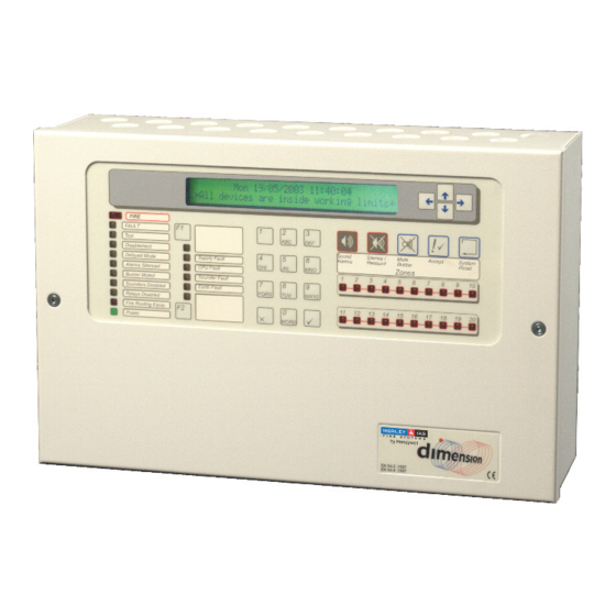
MORLEY-IAS Dimension Series 3 Controls and Indications Alphanumeric Liquid Crystal Display Navigation Keys Optional Key switch Control Keys ZONE FIRE LED Indicators PQRS WXYZ System Status LED WORD Indicators Numeric Keypad (Program / Interactive keys) Optional Printer E N 5 4 2 1 9 9 7 E N 5 4 4 1 9 9 7 Figure 1 –... -
Page 12: Table 2 - Alphanumeric And Interactive Control Keys
Dimension Series MORLEY-IAS Key Legend Symbol Function Function Key Programmable Function Key. Default is used as an event view short-cut function or alternatively can be assigned to the following: Bomb Alert, Class Change, Detection Mode start / stop. Function Key Programmable Function Key. -
Page 13: Front Panel Led Indications
MORLEY-IAS Dimension Series 3.2 Front Panel LED Indications Indicator Colour Function How to Clear Block 1 The panel has detected a fire alarm Correct the condition causing the alarm FIRE condition, or the ‘Sound Alarms’ key and then perform a panel reset. has been pressed. -
Page 14: Alphanumeric Display Indications
Dimension Series MORLEY-IAS • The Level 1 LED Indicators are divided into three blocks as described in Table 3 opposite. The LED Indicators illuminate as red, yellow or green. • Block 1 contains LED Indicators showing the state of the fire alarm control panel. •... -
Page 15: Panel Status Summary
MORLEY-IAS Dimension Series • Press the ‘F1’ key again to toggle to the next highest priority event category available. Where no category is available, the display will revert to the original summary/zone display. • Press ’X’ or any numeric key when viewing the active events and the display will revert to the summary display. -
Page 16: Level 1 Display Functions
Dimension Series MORLEY-IAS 4 Level 1 Display Functions EN54-2 5.1.1 • At Level 1, the panel operates in a display only mode with the control EN54 Display of keys disabled. functional • If fire alarm, fault, test or disablement conditions exist, the LED conditions. -
Page 17: Fire Alarm Conditions
MORLEY-IAS Dimension Series 4.2.1 Fire Alarm Conditions • If the control panel initiates an alarm condition, the FIRE LED Indicators will be illuminated and, if appropriate, the relevant ZONE FIRE LED Indicators will illuminate. The internal buzzer will sound and the alphanumeric display will indicate the number of fires. -
Page 18: Override Delays
Dimension Series MORLEY-IAS • To view other points in fire in this zone, press the keys (Note: The ‘ : more’ option is not shown if there is only one event, the ‘↓’ and ‘↑’ keys are shown for the first and last entries in the list). •... -
Page 19: Test Conditions
MORLEY-IAS Dimension Series • To view other zones in a fault condition (or to return to the main display), press the keys. EN54-2 8.3 • To view the devices (points) in a fault condition, press the key. The EN54 display then shows the first point in a fault condition in the selected Fault Signals from zone. -
Page 20: Disablement Conditions
Dimension Series MORLEY-IAS 4.2.4 Disablement Conditions • If zones, input devices, output devices or other disablement conditions have been programmed, the DISABLEMENT LED is illuminated along with other appropriate system condition LED Indicators. • To view more detailed information regarding the disablement conditions use the navigation keys as follows. -
Page 21: Other Conditions - By Event Display Option
MORLEY-IAS Dimension Series DISABLED 01/02 Z01 L1 A010 OPT 12:19 ←:back:more • The display shows the disablement number and the total number of devices (points) in a disablement condition in this zone (01/02), the Zone number (Z01), the loop number to which this device is connected (L1), the address of this device on the loop (A010), the type of device (OPT), the time at which the device was disabled (12:19) and the Point Location Text (20 character description) for this device. -
Page 22: Zone Fire Alarms
Dimension Series MORLEY-IAS • Non-displayed fires, faults, tests and disablements are always available by pressing the key, as indicated on the instruction screen. The subsequent event list will display all events in a priority order. The order is (highest-to-lowest) – fires, bomb alerts, security alerts, plant alarms, faults, disablements and tests. -
Page 23: Zone Faults
MORLEY-IAS Dimension Series INPUT OPEN CIRCUIT 01/02 MON INPUT 1 • In the example above, the display shows a description of the fault, event number and the total number of events and a panel input identifier. • Press the keys to scroll though the event list manually. If no key is pressed for 60 seconds, auto- scrolling will resume. -
Page 24: Panel Disablements
Dimension Series MORLEY-IAS 4.3.2.4.1 Panel Disablements DISABLE ALL SOUNDERS 01/03 12:15 • In the example above, the display shows a description of the event, the event number and the total number of events and the time at which the event (sounders disabled) was programmed (12:15). •... -
Page 25: List Of Device Abbreviations
MORLEY-IAS Dimension Series NO MAINS SUPPLY, BATTERY LOW, BATTERY DISCHARGED, BATTERY MISSING and CHARGER FAILURE. 4.5 List of Device Abbreviations • The following table gives a list of the device (point) abbreviations shown on the alphanumeric display. Abbreviation Description Carbon Monoxide Detector Flame Detector Ionisation Smoke Detector Input / Output Module... -
Page 26: Level 2 Display / Control Functions
Dimension Series MORLEY-IAS 5 Level 2 Display / Control Functions 5.1 Display Functions • All of the display functions available at Level 1 are also available at Level 2. 5.2 Control Functions • The four main control keys are locked at Level 1 (Note: Mute Buzzer key is always enabled). To enable the Level 2 control functions, press any control key and the following display will be shown: CONTROL KEY LOCKED –... -
Page 27: Level 2 Menu Functions
MORLEY-IAS Dimension Series 5.3 Level 2 Menu Functions • Press any number (0 – 9) key to display the Level 2 Menu Functions. These are normally inhibited from use and the alphanumeric display will prompt for entry of the Level 2 pass-code as follows. ACCESS TO MENUS RESTRICTED ←:BackSp Enter Level 2/3 passcode,... -
Page 28: Test
Dimension Series MORLEY-IAS 5.3.1 Test • To display the Test Menu, press ‘2’ and the display shows: [U0 Test] 1:LEDs 2:LCD 3:Zones 4:Outputs 5:Buzzer • It is possible to test: The LED’s on the front panel display. The alphanumeric (liquid crystal) display. The detection and alarm initiating devices connected to the signalling loop (i.e. -
Page 29: Configuring / Stopping Individual Zone Tests
MORLEY-IAS Dimension Series 5.3.1.3.2 Configuring / Stopping Individual Zone Tests • To configure or stop the testing of one or more zones individually, press ‘1’ and a new display is shown from which the zones to be tested can be selected as follows: [WALK TEST] Zone 1: NOT IN TEST ←→:Change :Select Zone... -
Page 30: Internal Outputs
Dimension Series MORLEY-IAS 5.3.1.4.1 Internal Outputs • To select the option, press ‘1’ and the display shows to first available panel output circuit as follows: [Internal Test] B:01 Sounder 1 :Start Test :Select Output X:Exit • Press the keys to select the required output. A full list of available outputs is detailed in the table below: •... -
Page 31: Audible Indicator (Buzzer) Test
MORLEY-IAS Dimension Series 5.3.1.5 Audible Indicator (Buzzer) Test • To select the option, press ‘5’. • To terminate the test, press ‘X’. • The buzzer will beep on and off. The test will automatically stop after 60 seconds. 5.3.2 Clock •... -
Page 32: Disable / Enable Functions
Dimension Series MORLEY-IAS 5.3.5 Disable / Enable Functions • To display the Disable / Enable Menu, press ‘4’ and the display shows the first page of options. Press keys to view the additional menu display: [U0 Disable/Enable] 1:Zone 2:Devices 3:Groups 4:Outputs :More [U0 Disable/Enable]... -
Page 33: Disable / Enable Individual Devices / Points
MORLEY-IAS Dimension Series NOTE: On entry, the display may indicate that the zone is ‘Part Disabled’. This is because one or more devices / points have been disabled individually. This zone disable / enable function will only FULLY Disable the zone or will re-enable the zone to the partial disablement condition (the panel remembers those devices that are individually disabled). - Page 34 Dimension Series MORLEY-IAS • To disable or enable a type of output circuit, press ‘4’ and the display shows a menu of the types of outputs. For example: [U0 Disable/Enable] 1:Sounders 2:Fault Relays 3:Others • It is possible to enable or disable: ALL Sounder Type Outputs.
-
Page 35: Disable / Enable Detection Mode
MORLEY-IAS Dimension Series 5.3.5.5 Disable / Enable Detection Mode EN54-2 7.11.2 • It is possible to manually override (turn on / off) detection mode EN54 Delays to delays. Outputs. • Detection Modes can be Stage 1 / Stage 2 Investigation Mode (see section 6) or Sensitivity Mode (Detector sensitivity is adjusted at certain times of the day) or Alarm Verification Mode (The signals from smoke detectors must be verified after a programmed period of time before a fire alarm is raised). -
Page 36: Disable / Enable Local Inputs
Dimension Series MORLEY-IAS • The delays are programmed in the Level 3 Commissioning Mode Functions. If there are no Pattern Delays configured, this option has no effect. • Press the ‘ ’ key to disable / enable these delays, as appropriate. •... -
Page 37: View Devices
MORLEY-IAS Dimension Series 5.3.6.1 View Devices • This function shows the information returned from the selected signalling loop device and is updated each time it is polled. The information is presented in a different for each protocol. • As each device status is ‘viewed’, the device LED for that address is illuminated – this can be a useful means of identifying individual devices on the system. -
Page 38: Apollo Device Information
Dimension Series MORLEY-IAS 5.3.6.1.2 Apollo Device Information [L1 Sensor 001] Type OPT Level 023 DISCOV Input(2-0):LLL Drift:+00 Mode:03 • The display shows the following information: Device Type: For a list of the device type abbreviations refer to Table 4 – Device Type Abbreviations. -
Page 39: View The Event Log
MORLEY-IAS Dimension Series 5.3.6.2 View The Event Log • Press ‘2’ to select the View Log option. The display shows the latest entry in the log. For example: [LOG 001/512] 08/05/03 11:23 MUTE INTERNAL BUZZER • The latest entry is always indexed as the entry number 001. The log has a maximum capacity of 512 entries. -
Page 40: View Service Information
Dimension Series MORLEY-IAS Typical Zone Disablement: DISABLED 01/03 12:19 ←:back DISABLE FULL ZONE :more Typical Output Circuit Disablement: DISABLED 01/02 12:19 ←:back DISABLE FAULT RELAYS :more Typical Device Disablement: DISABLED 01/02 Z01 L1 A010 OPT 12:19 ←:back:more • The information shown is the same as presented using the Level 1 disablement views. -
Page 41: View Voltages
MORLEY-IAS Dimension Series 5.3.6.7 View Voltages • Press ‘7’ to select the View Voltages option. The display initially shows the voltage across the battery. For example: [U0 VOLTS] BATTERY VOLTS = 23.6 :Select X:Exit • Press the keys to view other readings (see table below for full list of signals that can be viewed and their normal values). -
Page 42: Delayed Day Mode Operation
Dimension Series MORLEY-IAS 6 Delayed Day Mode Operation • The panel can be configured to operate in a delayed day mode during the daytime for any specified zone. • During this time, high sensor signals received from a detector will generate a fire alarm message on the panel but delay the ringing of the sounders. -
Page 43: Stage 2
MORLEY-IAS Dimension Series 6.2 Stage 2 • The stage 2 timer commences counting down as soon as ACCEPT key is pressed. • If the panel is not reset, using the SYSTEM RESET key, within the time allowed then a full fire alarm condition will be raised and the sounder outputs will activate. -
Page 44: Key-Switch And Function Key Operation
Dimension Series MORLEY-IAS 7 Key-Switch and Function Key Operation • The optional key-switch and the function keys (F1 and F2) can be used for a number of functions. The D E F Key-Switch use of these keys is M N O programmed by the installer PQRS W X Y Z... -
Page 45: Printer Operation
MORLEY-IAS Dimension Series 8 Printer Operation 8.1 Printout Samples RESOUND SOUNDERS • Tue 17/06/2003 14:55:10 The printer automatically prints fire alarm, SILENCE SOUNDERS fault conditions and other events as they Tue 17/06/2003 14:53:05 FIRE ALARM are written to the log. <... -
Page 46: Level 3 Programmer Functions
Dimension Series MORLEY-IAS 9 Level 3 Programmer Functions • Refer to the Product Manual (996-147) for complete information on installation, commissioning and programming the DX1e, DX2e and DX4e Fire Alarm Control Panels. 10 Maintenance / Inspection • The Equipment Owner shall ensure that a periodic Inspection BS5839-1: 2002 and Servicing Maintenance Schedule be followed. -
Page 47: Log Book Examples
MORLEY-IAS Dimension Series 10.2 Log Book Examples • Example pages are provided below and can be photocopied to produce a suitable logbook. The sample below is for reference data (e.g. the name of the responsible person), while the sample on the next page is for the entry of event information. -
Page 48: Table 9 - Logbook Event Data
Dimension Series MORLEY-IAS EVENT DATA Date Time Counter Event Action Required Date Initials Reading Completed Table 9 - Logbook Event Data User Manual Document No.996-148-000-5, Revision: 5 Page 43... - Page 49 MORLEY-IAS Dimension Series NOTES Page 44 Document No. 996-148-000-5, Revision: 5 User Manual...
- Page 50 © MORLEY-IAS. All rights reserved. ® The MORLEY-IAS Logo is a registered trademark. MORLEY-IAS Fire Systems, Charles Avenue, Burgess Hill. West Sussex. RH15 9UF. England Web site: www.morleyias.co.uk...