
Related Manuals for Honeywell MB-Secure 1000


Summary of Contents for Honeywell MB-Secure 1000
- Page 1 Installation Instructions Control panel MB-Secure 1000/2000/3000/4000/5000/6000 P00180-02-0G0-09 Subject to change EMBSC.00.0V05.xx without notice 2017-05-22...
-
Page 3: Table Of Contents
Installation Instructions MB-Secure 1000/2000/3000/4000/5000/6000 Contents General information............................... 4 Possible applications ..............................5 Control panel types ..............................5 Control panel version bundles ............................ 6 Types of housings(options) ............................6 Options for control panel configuration ........................7 Control panel design ..............................8 Control panel in the ZG 20 ............................ - Page 4 Installation Instructions MB-Secure 1000/2000/3000/4000/5000/6000 Symbols used in this documentation: Warning sign Indicates danger for man and/or machine. If this is not heeded, man and/or machine may be at risk. The level of hazard is indicated by the warning word: Caution! Risk of damage to material properties and the environment.
-
Page 5: General Information
Installation Instructions MB-Secure 1000/2000/3000/4000/5000/6000 General information Possible applications MB-Secure control units are designed to set up small to large security systems in private and commercial properties. They meet VdS Security Class C guidelines as well as EN50131 Grade 3. The standard model of the control panels includes the following features. -
Page 6: Control Panel Version Bundles
VdS class A is possible, for the system created with it. MB-Secure 1000 starter bundle Item no. 013821 - Computer/connection PCB MB-Secure 1000, Item no. 013820 - Control panel housing ZG20, Item no. 013730 - Power supply/charger unit 12 V / 18 Ah, Item no. 013970 - LED operating unit, Item no. -
Page 7: Options For Control Panel Configuration
Installation Instructions MB-Secure 1000/2000/3000/4000/5000/6000 Housing ZG4 for MB-Secure Item no. 013760 - Housing dimensions: W 580 mm x H 640 mm x D 300 mm - Place for 8 options and power supply unit; max. battery space 2 x 65 Ah 19”- Front panel 6HE for MB-Secure... -
Page 8: Control Panel Design
Installation Instructions MB-Secure 1000/2000/3000/4000/5000/6000 Control panel design The MB-Secure PCBs are compatible for installation in the following control panel housings: MB-Secure original control panel housing: 013730, 013740, 013750, 013760 Replacement of MB-Classic PCBs: 012911, 013201.10, 013202.10, 013106, 013203.10, 013204.10, 013222.10, 013223.10 Use in other housings is not recommended because the fixing points differ and correct grounding cannot be guaranteed. -
Page 9: Control Panel In The Zg 3.1
Installation Instructions MB-Secure 1000/2000/3000/4000/5000/6000 Control panel in the ZG 3.1 Emergency power supply The housing provides space for 2 batteries with max. 17 Ah. According to VdS guidelines the batteries are to be secured using a fixing strap (055280). Control panel in the ZG 4... -
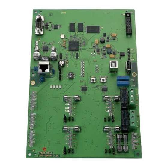
Page 10: Computer/Connection Pcb
Installation Instructions MB-Secure 1000/2000/3000/4000/5000/6000 Computer/connection PCB 1 = Jumper programming switching behavior relay 2 2 = DIP switches Switches Setting OFF Setting ON Manual release via TouchCenter Tuxedo / Permanent release for access with IQ PanelControl TouchCenter Plus for access with IQ PanelControl or macro function Factory use;... - Page 11 Installation Instructions MB-Secure 1000/2000/3000/4000/5000/6000 3 = USB device port (currently only for factory use) 4 = USB host port (Firmware update and USB stick as video data storage) 5 = Connector for connection cable to I-BUS users (in preparation) 6 = Power supply/charger unit connection...
-
Page 12: Directly Connectible Modulbus/Rs-485 Reader
Installation Instructions MB-Secure 1000/2000/3000/4000/5000/6000 25 = LEDs Ethernet (from top to bottom) LED 1 (green): Blinking -> Data transfer active Permanent On -> Ethernet connection ok LED 2 (green): Permanent Off -> Data transfer rate 10 MBit/sec Permanent On ->... -
Page 13: Extension Modules
Installation Instructions MB-Secure 1000/2000/3000/4000/5000/6000 Extension modules 2.6.1 MB-Secure Siren Module (item no.013920 1 = Connection Sirens 1 and 2; acoustic signaling device 048700/048720 (PCL) or 160455.10/160456.10* (intrusion/hold-up alarm) 2 = Flash lamp connection 3 = Outputs A1 to A4 12 V/50 mA... - Page 14 Installation Instructions MB-Secure 1000/2000/3000/4000/5000/6000 2.6.1.1 Programming jumpers/Monitoring resistors Programming jumpers P2/P3 terminating resistors RS-485 P2/P3 connected: Terminating resistors active P2/P3 not connected: Terminating resistors inactive Programming connection P4 signalling device type Position A: Signalling device 160455.10/160456.10* Position B: Signalling device 048700/048720 Monitoring resistors If signaling device 160455.10/160456.10* is...
-
Page 15: Awug Ds 6700 / Ds 6750 (Item No. 057864 / 057865)
Installation Instructions MB-Secure 1000/2000/3000/4000/5000/6000 2.6.2 AWUG DS 6700 / DS 6750 (item no. 057864 / 057865) Automatic transmission device with modem function and connection technology for PSTN (analog telephone network) as well as Ethernet connection technology. Can be integrated via the serial interface. - Page 16 Installation Instructions MB-Secure 1000/2000/3000/4000/5000/6000 10 = * Wire bridges for connecting/disconnecting +U_B within I-BUS 11 = * Plug for connection cable (I-BUS) to the next module 12 = Power supply unit connection points 13 = * BUS-2 connection points 14 = Grounding bridges (see chapter Grounding/shielding)
-
Page 17: Awug Ds 7700 (Part No. 057651.20)
Installation Instructions MB-Secure 1000/2000/3000/4000/5000/6000 2.6.3 AWUG DS 7700 (Part No. 057651.20) Automatic transmission device with modem function and ISDN connection technology as well as TCP/IP connection technology. Can be integrated via serial interface. Up to 100 transmission channels and 40 control inputs are available for transmission. - Page 18 Installation Instructions MB-Secure 1000/2000/3000/4000/5000/6000 9 = * Serial S1 (TTL level) 10 = * Output “resuscitation” for RFW 2000 11 = * Wire bridge for connecting/disconnecting +U_B within I-BUS 12 = * Plug for connection cable (I-BUS) to the next module...
-
Page 19: Installation
Installation Instructions MB-Secure 1000/2000/3000/4000/5000/6000 Installation Also see brochure “Electrical installation of hazard detection devices " (no. P03061-15-000-XX). Mounting The device is intended for wall mounting. The housing (option) consists of a back panel and a detachable housing rack with front door (not ZG20 and ZG4). -
Page 20: Installation In 19"- Cabinet/Housing (Third-Party Products)
Installation Instructions MB-Secure 1000/2000/3000/4000/5000/6000 If Intruder alarm systems also display fault signals optically or acoustically in armed mode (allowed only for displays outside the protection zone), the power consumption of these displays must also be taken into account. In addition, VDE guidelines and local public utility regulations must be complied with. -
Page 21: Current Consumption Of Control Panel Components, Detectors And/Or Users
Installation Instructions MB-Secure 1000/2000/3000/4000/5000/6000 Current consumption of control panel components, detectors and/or users The current values specified are approximate values. The values specified for Active Mode are maximum values - e.g. with LED displays, relays pulled in. The exact total power consumption must be... -
Page 22: Calculation Of Accumulator Capacity
Installation Instructions MB-Secure 1000/2000/3000/4000/5000/6000 Calculation of accumulator capacity To calculate the accumulator capacity required, the overall system current consumption must be known. The current consumption is determined by measuring consumption with accumulator(s) connected when there is no power supply. For systems of VdS Class C, a bridging time of 60 hours is prescribed in the case of power failure. -
Page 23: Grounding/Shielding
Installation Instructions MB-Secure 1000/2000/3000/4000/5000/6000 Grounding/Shielding To protect against electromagnetic interference coupling such as occurs when electronic devices are switched on and off, shielded cables must be installed and a suitable shielding circuit must be provided. Care must be taken to connect the cable shields in the distributor sockets in such a way that they are not in contact with other potentials. -
Page 24: Lines
Installation Instructions MB-Secure 1000/2000/3000/4000/5000/6000 3.10 Lines All DC connections must be made using shielded telephone cables J-Y(ST)Y / J-H(ST)H. These are installation cables based on VDE 0815, with a static shield for telephone, measurement and signal transmission. They are suited for installation in dry and humid plants and factories, with surface or flush mounting, as well as outdoors using fixed laying. - Page 25 Installation Instructions MB-Secure 1000/2000/3000/4000/5000/6000 - Do not install any cables with interferences pulses in parallel with the BUS cables. - Maintain the minimum distance from high current cables running in parallel, in accordance with VDE guidelines. - Install according to VDE guidelines (VDE 0800 Part 4).
- Page 26 Installation Instructions MB-Secure 1000/2000/3000/4000/5000/6000 Connection BUS-2 User Connection BUS-2 User with alternate U_ext-feed Special information regarding IB2 topology Utilization of cables J-Y(ST)Y, J-H(ST)H, J-2Y(ST)Y. Cable diameter 0.6 mm and 0.8 mm. Different cables should not be used together. Star quad can be used (J-2Y(ST)Y).
- Page 27 Installation Instructions MB-Secure 1000/2000/3000/4000/5000/6000 Connection of IB2 / Modulbus/RS-485 User Terminating resistors and line lengths IB2 If the controllers are operated in IB2 mode, the terminating resistors on the computer/connection PCB of the control panel and the connection PCB of the BUS users are to be set as follows. Likewise the maximum line lengths are to be observed.
- Page 28 Installation Instructions MB-Secure 1000/2000/3000/4000/5000/6000 Terminating resistors and line lenghts of Modulbus/RS-485 Shield connection Picture of the shielding connection terminal (example)
-
Page 29: 3.10.3 Sample Cable Calculation For Users
Installation Instructions MB-Secure 1000/2000/3000/4000/5000/6000 3.10.3 Sample cable calculation for users Assumption: The cable length to be installed is approximately 150 meters. Users connected to a BUS connection require a maximum current of 150 mA. The installation should be performed using telephone cable (cable diameter 0.6 mm = 0.28 mm... - Page 30 Installation Instructions MB-Secure 1000/2000/3000/4000/5000/6000 The required number of wires per connection (+12V DC and 0V) can also be easily determined on the basis of the following diagram. The "pointer" refers to the sample calculation. According to the calculation, the vertical pointer at the point of intersection shows 150 mA/150 m or just below 6 wires of diameter 0.6 mm or more than 3 wires of diameter 0.8...
-
Page 31: Special Notes On Installation And Planning
Installation Instructions MB-Secure 1000/2000/3000/4000/5000/6000 3.11 Special notes on installation and planning Software version IDENT-KEY evaluation unit 023312.10 / door controller module for MB 023350 To operate a IDENT-KEY IK3 evaluation unit or a access control BUS-2 door module in conjunction with the MB-Secure control panel, the evaluation unit or door controller module must compulsorily be at software version V12 or higher. -
Page 32: Main Zone Extension Via Ib2 In Remote Housing (As Per Vds)
Installation Instructions MB-Secure 1000/2000/3000/4000/5000/6000 3.12 Main zone extension via IB2 in remote housing (as per VdS) In accordance with the VdS guideline, when an IB2 BUS extension is used in a remote housing, the installation of the IB2 to the expander module must be implemented in protected installation (see VdS 2311) In addition, the IB2 BUS expansion module(s) must be assigned to the "contral panel"... -
Page 33: Start-Up Procedure
Installation Instructions MB-Secure 1000/2000/3000/4000/5000/6000 Start-up procedure Preparations before start-up The operation of the control panel requires operating and display elements that provide information about the current status of the system and allow the operator or installer to gain access to system functions. -
Page 34: Starting Operation With Video Function
Installation Instructions MB-Secure 1000/2000/3000/4000/5000/6000 The connection between the control panel and the PC/laptop is created via Ethernet. A crosslink cable (direct connection) can be used, or the control panel and PC are on a network. Launch IQ PanelControl on the PC/laptop and carry out the programming. -
Page 35: Firmware Updates
Installation Instructions MB-Secure 1000/2000/3000/4000/5000/6000 Firmware updates Firmware updates should be performed only by trained technical personnel. Please watch out for static discharge! We always recommend loading the latest version of the firmware in the control panel. This is available for free download on our Internet site. -
Page 36: Specifications
Installation Instructions MB-Secure 1000/2000/3000/4000/5000/6000 Specifications Rated operating voltage 12 V DC Operating voltage range 10.5 V to 15 V DC Detector group voltage (terminal works as input) 8 V DC Current consumption at rated voltage - disarmed group connections open... -
Page 37: Connection Diagrams
Installation Instructions MB-Secure 1000/2000/3000/4000/5000/6000 Connection diagrams Connection of MB-Secure Siren module Connection and activation of signaling devices 160455.10/160456.10, in preparation... -
Page 38: Connection Of Compact Alarm Unit And Pcl
Installation Instructions MB-Secure 1000/2000/3000/4000/5000/6000 Connection of compact alarm unit and PCL Diagram Connection diagram of compact alarm unit and PCL in the protective housing... -
Page 39: General Connection Of Alarm Detectors "Z-Wiring
Installation Instructions MB-Secure 1000/2000/3000/4000/5000/6000 General connection of alarm detectors "Z-wiring" Z-contacts → Detectors that are powered by an external voltage source and are looped into the detector group using a zero potential relay contact, and simple contacts without external power supply, e.g. -
Page 40: Connection Ident-Key Ik3-Evaluation Unit 023312.10
Installation Instructions MB-Secure 1000/2000/3000/4000/5000/6000 Connection IDENT-KEY IK3-evaluation unit 023312.17 Connector ST14 is no real output. The connector is a free soldering terminal and can be used, for instance, to tap U_ext. Here, the control panel must supply U_ext at the customer’s premises. -
Page 41: Connecting An Electromechanical Blocking Element (019030.20/019033)
Installation Instructions MB-Secure 1000/2000/3000/4000/5000/6000 Connecting an electromechanical blocking element (019030.20/019033) Diagram Connection of an electromechanical blocking element... -
Page 42: Connection Diagram Of Transmission Device Ds 6700/Ds 6750 (057864/057865)
Installation Instructions MB-Secure 1000/2000/3000/4000/5000/6000 Connection diagram of transmission device DS 6700/DS 6750 (057864/057865) -
Page 43: Connection Diagram Of Transmission Device Ds 7700 (057651.20)
Installation Instructions MB-Secure 1000/2000/3000/4000/5000/6000 Connection diagram of transmission device DS 7700 (057651.20) -
Page 44: Connection Diagram Of Computer/Connection Pcb
Installation Instructions MB-Secure 1000/2000/3000/4000/5000/6000 Connection diagram of Computer/Connection PCB Connection diagram of Computer/connection PCB Controllers 1 - 4 For BUS-2 operation, connection B should not be used. -
Page 45: Connection To Power Supply / Charger Unit 013950/013960 According To Vds Guidelines
Installation Instructions MB-Secure 1000/2000/3000/4000/5000/6000 Connection to power supply / charger unit 013950/013960 according to VdS guidelines for 1 The operating voltage of the individual bus branches has to be supplied via the "external load" connections on the power supply unit. In addition, the fuse for the corresponding bus branch is to be removed on the computer/connection PCB. -
Page 46: Connection To Power Supply / Charger Unit 013970
Installation Instructions MB-Secure 1000/2000/3000/4000/5000/6000 7.10 Connection to power supply / charger unit 013970 Protective earthing When the power supply unit 013970 is mounted in a metal housing, a conductive connection must be established between the protective earth connection (E) of the power supply unit and the housing. -
Page 47: Notes
Installation Instructions MB-Secure 1000/2000/3000/4000/5000/6000 Notes... - Page 48 Honeywell Security Group Novar GmbH Johannes-Mauthe-Straße 14 P00180-02-0G0-09 72458 Albstadt, Germany 2017-05-22 www.security.honeywell.com © 2017 Novar GmbH...