Table of Contents
Quick Links
Table of Contents

Related Manuals for Bosch D8128D


Summary of Contents for Bosch D8128D
- Page 1 OctoPOPIT Module D8128D Installation Guide...
-
Page 2: Table Of Contents
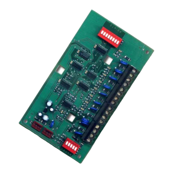
Figure 3: D8128D OctoPOPIT Layout............................7 Figure 4: Mounting Enclosure ................................. 8 Figure 5: Wiring the D8128D to the Panel with a D8125 POPEX Module ................. 9 Figure 6: Wiring Multiple D8128Ds using Molex Connectors....................10 Figure 7: D8128D OctoPOPIT Sensor Loops..........................10 Tables Table 1: D8128D Installation Instructions Organization ...................... -
Page 3: Introduction
The D125B Dual Powered Loop Interface Module or the D129 Dual Class “A” Module zone outputs may be connected directly to the point inputs on the D8128D. Use the D125B to connect 2-wire smoke detectors. Typically, the D129 is used for connecting waterflow switches. -
Page 4: D8128D Overview
Review the Power Outputs section of your panel’s Operation and Installation Guide to be sure you provide enough power for the OctoPOPITs and other powered devices you wish to connect to your system. The D8128D is designed for use with the Bosch Security Systems’ panels shown in Table 3. (Also shown are previously manufactured D8128 OctoPOPIT Modules.) -
Page 5: Table 4: Maximum D8128D Connections
OctoPOPITs on the D7212B1 and D9112B1 Control Panels. The maximum number of D8128D Modules that can be connected to your system depends on the control panel being used (see Table 4). Please refer to Table 7 through Table 10 for proper switch settings. -
Page 6: Figure 1: D8129 Connections To The D9412G
D8128D D8128D Overview Figure 1: D8129 Connections to the D9412G Figure 2: D8129 Connections to the D7412G D8128D Installation Guide 41343F Page 6 © 2004 Bosch Security Systems, Inc. -
Page 7: Installation
Use the point DIP switches to disable conflicting points, such as when a D9210B Access Control module must be assigned to a point that falls within the range of the D8128D OctoPOPIT. In this example, a D9210B is assigned to Point 20. On the same system, a D8128D OctoPOPIT is assigned to Points 17 through 24. -
Page 8: Mounting The Octopopit
Power down the panel by disconnecting the positive (red) battery lead at the battery and unplugging the transformer. The D8128D can be installed up to 200 ft. (61 m) from the control panel. There are two methods for connecting the D8128D to a control panel: wire the OctoPOPIT to the control panel using the terminal strip on the side of the module or connect using the Molex connectors (P1 and P2). -
Page 9: Figure 5: Wiring The D8128D To The Panel With A D8125 Popex Module
POPEX D9127U/T 33 k ohm EOL (P/N: 15-03130-002) Positive (+) Negative (-) ZONE EXPANSION LOOP Figure 5: Wiring the D8128D to the Panel with a D8125 POPEX Module D8128D Installation Guide © 2004 Bosch Security Systems, Inc. Page 9 41343F... -
Page 10: Connecting The D8128D To The Control Panel Using Molex Connectors
When connecting multiple D8128Ds to a control panel, you may connect the control panel terminals to P1 or the Com, In, Out, and +12V terminals on the first D8128D and then connect P2 of the first D8128D to P1 of the second D8128D and so on. -
Page 11: D8128D Octopopit Switch Settings For D9412, D9412G, D9124, And D9112
D8128D Installation 3.4.2 D8128D OctoPOPIT Switch Settings for D9412, D9412G, D9124, and D9112 ZONEX 1 D8128D Address Switches ZONEX 2 Refer to Table 7 to set the OctoPOPIT switches for use with Points 9 Points 129 through 127 through 247 the D9412, D9412G, D9124, and D9112 Control Panels. -
Page 12: D8128D Octopopit Switch Settings For D7212B1
3.4.5 D8128D OctoPOPIT Switch Settings for D7212B1 ZONEX 1 D8128D Address Switches Refer to Table 10 to set the OctoPOPIT switches for use with the Points 9 D7212B1 Control Panel. through 48 * Line Termination Switch (see 9-16 Section 3.1.1.2 Line Termination 17-24 Switch Settings).