Socomec ATyS C25 - ATS Controller Quick Start Guide
Also See for ATyS C25:
- Instruction manual (38 pages)
Table of Contents
Contents
Socomec ATyS C25 - ATS Controller Quick Start Guide
Mounting
DIN rail mounting
- Mounting

- Unmounting


Door mounting (IP 40)
dimensions in mm.
")
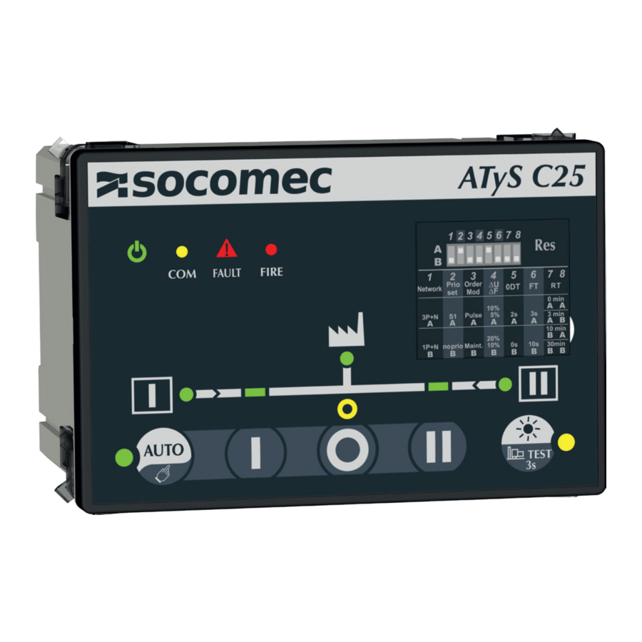
HMI

Hysteresis & Timers

Standards
| IEC 60947-6-1* | IEC 61010-2-201 | IEC 61010-2-030 | GB/T 14048.11 appendix C | |
| Voltage Sensing | 50-300Vac L/N 90-520Vac L/L' | |||
| Mesurement Cat. | CAT III | |||
| Frequency | 50-60Hz | 50-60Hz | 50-60Hz | 50Hz |
| Overvoltage Cat. | III | III | III | |
| U imp | 4kV | 6kV** | ||
*When type tested with IEC 60947-6-1 RTSE
**Test level; Between SOURCES
Connection with ATyS

Dimensions
dimensions in mm 
Settings


Product must be in manual mode (LED 7 OFF) for configuration changes.
After changing DIP switch settings press RES button shortly (<3s) to validate.
| DIP Switch | ||
| A | Three phase network |
| B | Single phase network | |
| A | Prioritty source 1 |
| B | No priority | |
| A | Control mode impulse logic |
| B | Control mode contactor logic | |
| 4. ΔU/ΔF | A | Overvoltage setting at 10% of nom voltage / overfrequency setting 5% of nominal frequency (hysteresis value is 20% of ΔU/ΔF) |
| B | Overvoltage setting at 20% of nom voltage / overfrequency setting 10% of nominal frequency (hysteresis value is 20% of ΔU/ΔF) | |
| A | Load supply down time of 2 second (0DT = 02 sec) |
| B | Load supply down time of 0 second (0DT = 0 sec) | |
| A | Wait time of 3s before source is lost ( Fail timer = 3s) |
| B | Wait time of 10s before source is lost ( Fail timer = 10s) | |
| 7/8. RT | AA | Wait time of 0min (3s) before source returns ( retrun timer = 0min (3s)) |
| AB | Wait time of 3min before source returns ( retrun timer = 3min) | |
| BA | Wait time of 10min before source returns ( retrun timer = 10min) | |
| BB | Wait time of 30min before source is lost returns ( retrun timer = 30min) | |
Technical characteristics
| Denomination | Terminal | Description | Characteristics |
| Control signal outputs (orders to RTSE) | 14 | Position II order | AC1 – General use – Ie: 5A, Ue: 250 V.a.c DC1 – General use – Ie: 5A, Ue: 30 V.d.c AC15 - Ie: 3A, Ue: 120 V.a.c AC15 - Ie: 1.5A, Ue: 240 V.a.c DC13 - Ie: 0.22A, Ue: 125 V.d.c DC13 - le: 0.11A, Ue: 250 V.d.c |
| 15 | Position I order | ||
| 16 | Position 0 order | ||
| 17 | Common point for position output | ||
| RS485 | 35 | NC – Not connected | RS485 Isolated bus |
| 36 | Negative electrode | ||
| 37 | Positive electrode | ||
| Genset output | 51 | Common point | |
| 52 | Closed to start the Genset (closed when controller is powered off) | AC1 – General use – Ie: 3A, Ue: 250 V.a.c DC1 – General use – Ie: 3A, Ue: 30 V.d.c AC15 - Ie 54/51: 3A 52/51: 1.5A Ue: 120 V.a.c AC15 - Ie 54/51: 1.5A 52/51: 0.75A Ue: 240 V.a.c DC13 - Ie 54/51: 0.22A 52/51: 0.22 A 125 V.d.c DC13 - Ie 54/51: 0.11A 52/51: 0.11 A 250 V.d.c | |
| 54 | Open to start the genset | ||
| Controller inhibit input | 63A | Controller is inhibited when this contact is open | Do not use external voltage - Power from common point |
| 64A | |||
| Return of information from RTSE (Position inputs) | 70 | Common point for position inputs | Do not use external voltage - Power from common point |
| 71 | Position I RTSE | ||
| 72 | Position II RTSE | ||
| 73 | Position 0 RTSE | ||
| Fire input | F1 | Negative electrode of the 24 V.d.c | 12-24 V.d.c |
| F2 | Positive electrode of the 24 V.d.c | ||
| Optional Aux supply 24V.d.c | 81 | Negative electrode of the 24 V.d.c | 10-30 V.d.c (Auxiliary supply for controller, does not supply RTSE) |
| 82 | Positive electrode of the 24 V.d.c | ||
| Source 1 and 2 voltage inputs | 103 | Source 1 N | Sensing range: 90-520 V.a.c (ph-ph) 50-300 V.a.c (ph-n) 45-65 Hz Supply: 184-300 V.a.c* (ph-n) 45-65 Hz Max consumption 10 W *200-300 V.a.c in maintained mode |
| 104 | Source 1 L1 | ||
| 105 | Source 1 L2 | ||
| 106 | Source 1 L3 | ||
| 203 | Source 2 N | ||
| 204 | Source 2 L1 | ||
| 205 | Source 2 L2 | ||
| 206 | Source 2 L3 | ||
| DPS output (RTSE power supply) | 301 | Phase output | AC – General use – Ie: 6A, Ue: 250 V.a.c DC – General use – Ie: 6A, Ue: 30 V.d.c AC15 - Ie: 3A, Ue: 120 V.a.c AC15 - Ie: 1.5A, Ue: 240 V.a.c DC13 - Ie: 0.22A, Ue: 125 V.d.c DC13 - le: 0.11A,Ue: 250 V.d.c |
| 302 | Neutral output |
Connectors
Connectors top view 
Connectors bottom view 

CORPORATE HQ CONTACT: SOCOMEC SAS,
1-4 RUE DE WESTHOUSE,
67235 BENFELD, FRANCE
www.socomec.com
To download, brochures, catalogues and technical manuals

Documents / Resources
References
Download manual
Here you can download full pdf version of manual, it may contain additional safety instructions, warranty information, FCC rules, etc.


