
Related Manuals for socomec ATyS C55


Summary of Contents for socomec ATyS C55
- Page 1 INSTALLATION AND OPERATING MANUAL ATyS C55/65 ATS Controller www.socomec.com To download, brochures, catalogues and technical manuals.
-
Page 2: Table Of Contents
11.10. The visualisation POP-UPS ............34 ATyS Controller C55/65 - 549866C - SOCOMEC... - Page 3 14.4. Configuration through EasyConfig System software ........76 ATyS Controller C55/65 - 549866C - SOCOMEC...
- Page 4 Annex 16 - 6. ATyS C55/C65 Technical characteristics ....... . .
- Page 5 ATyS Controller C55/65 - 549866C - SOCOMEC...
-
Page 6: General Safety Instructions
• This manual provides instructions on safety, connections instructions on the SOCOMEC ATyS C55 / C65 ATS controller. • Whether the ATyS C55 / C65 is sold as a loose product, as a spare, in a kit or as part of an enclosed solution or in any... -
Page 7: Introduction
2. INTRODUCTION ATYS C55 and C65 ATS controllers are compliant to international product standards and are designed specifically for use in low voltage power applications to ensure the safe transfer of a load supply between a normal and an alternate source. -
Page 8: Quick Start
To download, brochures, catalogues and technical manuals IEC 61010 The use of this input is optional, when used configure IN6 to «DOOR OPEN» in mode «NC». Non contractual document. Subject to change without notice. ATyS Controller C55/65 - 549866C - SOCOMEC... - Page 9 Screw Tightening torque PH1 / 0.2 Nm / 1.77 lb.in Gasket for IP 65 Backplate mounting 0.31 ±0,004 0.25 ±0,1 R 0.24 R 6,25 0.07 Clip the mounting feet in Screws not delivered with product the designated slot ATyS Controller C55/65 - 549866C - SOCOMEC...
- Page 10 When powered for the first time the controller will prompt the user to configure using the wizard. To access the wizard input code 1000 then the configuration will go as follow: Switch & Language Time & date Source config Product Name Communication Application For advanced configuration go to parameters menu. ATyS Controller C55/65 - 549866C - SOCOMEC...
- Page 11 LINE I4 WAY FAULT LOG BACK DISPLAY SCHEDULER SCREEN GENERAL PARAMETERS DATE AND TIME CUSTOM 1 LED CONFIG CUSTOM 2 OPTIONS CUSTOM 3 CHANGE PRODUCT NAME CUSTOM 4 C65 only SCREENSAVER TEXT Non co Subjec ATyS Controller C55/65 - 549866C - SOCOMEC...
-
Page 12: General Overview
4. GENERAL OVERVIEW The ATyS C55/C65 ATS Controller reference includes: - 1 ATS Controller - 1 ATyS C65 IP65 gasket (available as accessory for C55) - 1 ATyS Cx5 door mounting kit - 1 ATyS Cx5 backplate mounting kit - Quickstarts instruction sheet All other components described in this instruction manual are available as accessories and sold separately. -
Page 13: Environmental
• 95% humidity without condensation at 55°C 5.3.3. Altitude • Up to 2000m 5.4. Storage Conditions 5.4.1. Temperature • From -40 to +70°C 5.4.2. Hygrometry • Recommendation: to be stored in dry, non-corrosive and non-saline atmospheric conditions. ATyS Controller C55/65 - 549866C - SOCOMEC... -
Page 14: Storage Duration Period
• Maximum of 5 boxes may be stacked vertically 5.4.5. Volume and shipping weights by reference ATyS Weight (kg) Reference Volume (mm) Product Number inc packing Gross ATyS C55 1600 0055 1,060 1,500 295x255x115 (LxWxH) ATyS C65 1600 0065 1,080 ATyS Controller C55/65 - 549866C - SOCOMEC... -
Page 15: Standard Compliance And Marking
NFPA 110* (Specific UL Reference). (*) For a UL certified product, SOCOMEC provide reference 1600 0066 (ATyS C66, that is UL61010 listed and UR 1008 recognised as a standalone ATS controller as well as UL1008 listed in association with ATyS FT or ATyS DT transfer switching equipment) 7. -
Page 16: Installation
8.66 48,10 8.2. Mounting The ATyS C55/65 can be mounted either on the door or on the backplate of an enclosure (both mounting kits are delivered with the product). 8.2.1. Door mounting The ATyS C55/C65 can be mounted on doors up to with a thickness 4mm (0.15in). -
Page 17: Backplate Mounting
STEP 1: Placing the 4 mounting legs on the controller Insert the mounting legs into the 4 slots (2 top side and 2 bottom side, (cf. below top side view). 0.31 ±0,004 0.25 ±0,1 R 0.24 R 6,25 0.07 ATyS Controller C55/65 - 549866C - SOCOMEC... - Page 18 OUT 2 OUT 1 Optional Aux. Supply INPUTS/ENTRÉES LATCHING RELAY OUTPUTS (NC-NO-C) OUTPUT RELAYS (NC-NO-C) (6W) ATyS C65 ATSE Controller An end-of-the-bus resistor is necessary for a correct communication between the modules and the controller: ATyS Controller C55/65 - 549866C - SOCOMEC...
- Page 19 The configuration and the state (function and active or off) of the additional I/O can be visualized at any time by going to Dashboard 7 "I/O" and selecting submenus 7.3 "EXTERNAL INPUTS" and 7.4 "EXTERNAL OUTPUTS" ATyS Controller C55/65 - 549866C - SOCOMEC...
-
Page 20: Connection
To help secure the control cables during the wiring, the controller includes seven fixing supports on the back of the controller to retain the cables in place using cable ties. Example of cable way. ATyS Controller C55/65 - 549866C - SOCOMEC... - Page 21 - Use 90°C copper wire for installations with ambient temperature from 35-60°C. When the ambient temperature is above 60°C, Use 105°C copper wire. * Impulse voltage withstand tests at 6kV between phases of the same source and 8kV between phases of a different source. ATyS Controller C55/65 - 549866C - SOCOMEC...
-
Page 22: Power Supply
9.4. DC Power Supply The ATyS C55/65 includes an optional DC power supply input to power the controller in case both sources are off for over 15-30 seconds. The DC power supply voltage needed to power up the controller is between 9VDC and 28VDC. The 24VDC power supply is mandatory when using the C65 with additional external I/O modules. -
Page 23: Energy Backup
TRANSFORMATEURS DE COURANT : 1A ou 5A SOURCE S2 SOURCE S1 GND GND 120Ω RS485 The configuration for the measurement should be done in the Parameters/Load menu (see chapter "14.1.2. LOAD parameters menu (only C65)", page 53). ATyS Controller C55/65 - 549866C - SOCOMEC... - Page 24 GND GND GND GND GND GND C-65 VT - VOLTAGE TRANSFORMER C-65 C-65 C-65 GND GND GND GND C-65 C-65 WARNING ! One of the GND inputs must be grounded. C-65 C-65 GND GND C-65 ATyS Controller C55/65 - 549866C - SOCOMEC...
-
Page 25: Command Circuits
GENSET START Logic Impulse Impulse Maintained Impulse Impulse See chapter specific functions for more details. Impulse duration and length and number of retries can be configured in "MAIN MENU" > "PARAMETERS" > "NETWORK" > "APPLICATION". ATyS Controller C55/65 - 549866C - SOCOMEC... - Page 26 Open* * The ATyS C55/C65 include two bi-stable relays with backup energy, when the controller loses all sources of power supply (DPS, DC supply), the outputs 5 & 6 will activate using their independent backup power after the fail timer has timed out or 60s max from power failure detection. This is a safety feature is designed to ensure power availability to the load in Main-Genset or Genset-Genset application by forcing generators to start in case of total power loss.
-
Page 27: First Power Up - Smart Wizard
• To use the manual configuration: user will enter manually all network configuration values. The controller will require the configurator 4-digit password before the configuration (by default, 1000). ATyS Controller C55/65 - 549866C - SOCOMEC... - Page 28 CAUTION ! Make sure that the settings are matching your installation for the correct functioning of the transfer switch. Switch technology stands for the type of switch used with the controller. The options are: ATyS Controller C55/65 - 549866C - SOCOMEC...
- Page 29 The 7th step will not affect the functioning of the transfer switch but allows the user to select a name for the product. Default name is ATyS C55/65, but it can be changed to any combination of letters, numbers and signs, for instance, “Cooling”, “Line 1”...
-
Page 30: Visualisation Options
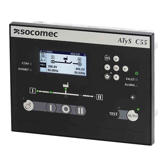
*This is available only for the screens of the dashboard menu All the dashboards have the same display format as follows: Dashboard name Screen name Favourite Date/Time Active alarms Information Screen navigation Optional shortcuts ATyS Controller C55/65 - 549866C - SOCOMEC... -
Page 31: Mimic
This information is also detailed in the status screen 2.1. 11.3. Status Give more detailed information on the sources STAT: informs the user on the availability of each source. SYNC: Information on the voltage, frequency and phase angle of both sources. ATyS Controller C55/65 - 549866C - SOCOMEC... -
Page 32: Metering
Q: Reactive power phase by phase. S total apparent power phase by phase Pf: Power factor phase by phase. Ea: Active energy. Er: Reactive energy. Es: Apparent energy. RST E : Resets the energy measured. ATyS Controller C55/65 - 549866C - SOCOMEC... -
Page 33: Timers
Allows the user to visualise the configuration of the I/O. The settings for the inputs and outputs on the controller will be shown as well as the external I/O modules (if being used). IN: Controller inputs. OUT: Controller outputs. E.IN: External inputs (IO10 modules). E.OUT: External outputs (IO10 modules). ATyS Controller C55/65 - 549866C - SOCOMEC... -
Page 34: Maintenance
"MAIN MENU" > "PARAMETTERS" > "DISPLAY" > "OPTIONS" > "POPUP DISPLAYED". Note: if timer pop-ups are deactivated the function to bypass current active timer with inputs or communication will not be functional. (bypass timers through the TIMER dashboard will still be functionnal). ATyS Controller C55/65 - 549866C - SOCOMEC... -
Page 35: Operation And Control
Long press: Sets the current dashboard screen as favourite (C65 only) Press: Enter / OK / set a value / accept / confirm OK/Save & Quit Long press: (only when configuring) Save and Quit (back to previous configuration screen) ATyS Controller C55/65 - 549866C - SOCOMEC... -
Page 36: Navigation Menu
To switch from manual mode to Automatic mode, make sure there are no external inhibitions to automatic mode (inputs, cover open, etc..) and click the automatic operation button: The LCD will prompt the user to enter the operator password. The automatic mode LED will light up. ATyS Controller C55/65 - 549866C - SOCOMEC... -
Page 37: Availability Conditions
- Loss of Phase: will be detected in all cases. Note: The controller will not detect any phase/neutral wire failure downstream of the switching device. ATyS Controller C55/65 - 549866C - SOCOMEC... - Page 38 The state of the position LED is entirely dependent on the inputs programmed for position inputs. If no position inputs are programmed the position LED will blink based on the expected position of the swicth (controller will expect that switching orders have been taken into account correctly by the switch immediately). ATyS Controller C55/65 - 549866C - SOCOMEC...
-
Page 39: Test Operating Mode
TEST ON LOAD will cause a load supply interruption when testing the transfer function as the load will change from one source to another in open transition. For more information on the tests sequence see "Annex 16 - 5. Operating sequences", page 96. ATyS Controller C55/65 - 549866C - SOCOMEC... -
Page 40: Main Menus Details
Example: mode can be inhibited, but when entering the menu the mode will say “automatic” (which is not the current mode, it is possible orders to be used). - TEST: permits launching a TEST ON LOAD or a TEST OFF LOAD. See chapter "12.6. Test operating mode", page ATyS Controller C55/65 - 549866C - SOCOMEC... -
Page 41: Log/Event History
- ALARM LOG: the log can store up to 100 alarms or faults. Inside alarm log screen, there are 2 options: in progress and history. “In progress” shows all active alarms and the history shows all the last finalised alarms. ATyS Controller C55/65 - 549866C - SOCOMEC... -
Page 42: Statistics Menu
• Source 1 / Source 2 data (total time in source, partial time, last switch, total time on load) • Genset 1 / Genset 2 data (total active time, total active time on load, genset start counter) • Breaker : Number of trips and date of last trip ATyS Controller C55/65 - 549866C - SOCOMEC... -
Page 43: Genset Scheduler / Engine Exerciser Menu
“CUSTOM 1” is priority over the “CUSTOM 2” if both tests are scheduled to occur at the same time. This is to avoid exercising a genset that is already being exercised. Only for ATyS C65, ATyS C55 has 1 Custom engine exerciser program GENERAL PARAMETERS includes a GENSET IDLE TIMEOUT setting, this setting dictates the time for which the genset must be off before another automatic test can be launched (this includes automatic and manual starts on the genset), if the amount of time configured has not passed the Custom test will not be launched. - Page 44 In case the start time is the same for 2 or Custom 1 ends more Custom tests, the lowest number properly after its takes over. Therefore here, Custom 1 original duration ends starts fter its uration ATyS Controller C55/65 - 549866C - SOCOMEC...
-
Page 45: About
MAIN MENU” > “MAINTENANCE” > ”INTRODUCE PHONE NUMBER” 13.6. Other main menus The menus, parameters, specific functions and mainteance are detailed in the next chapter configuration. For the full menu architecture see "Annex 16 - 7. Full menu architecture", page 101. ATyS Controller C55/65 - 549866C - SOCOMEC... -
Page 46: Configuration
14. CONFIGURATION The configuration on the ATyS C55/65 can be done: - Directly on the HMI. - By USB connection to the controller (using EasyConfig software, available for free download at www.socomec.com). - Through communication (DIGIWARE or RS485). Note: The configuration can be done even without cabling the AC or DC supply to the controller, only connecting it to a computer with an USB cable. -
Page 47: Network Parameters Menu
WARNING ! In order to save the settings it’s mandatory to select SAVE CONFIG on the bottom of the screen or press the "OK" button for 1.5s and a pop-up will appear asking for confirmation before “save & exit”. ATyS Controller C55/65 - 549866C - SOCOMEC... - Page 48 - SWITCH TECHNOLOGY – Type of switching device / RTSE. Options are: • ATyS r/d (remote / double supply) makes reference to any Socomec type ATyS r, ATyS d, ATyS dM, ATyS dH, ATyS S/Sd switches or equivalent motorized switch-based RTSE.
- Page 49 For each parameter, the limits can be set in % vs the nominal value and there are two parameters to set: the threshold value that will make the source be considered unavailable (FAIL) and the hysteresis value that will make the source be considered available again (RESTORE). ATyS Controller C55/65 - 549866C - SOCOMEC...
- Page 50 097% ** Adjustment range given: • As a % of U nominal for Over and Undervoltage • As a % of U avg in case of unbalances. • As a % of nominal frequency ATyS Controller C55/65 - 549866C - SOCOMEC...
- Page 51 Source 1 Source 2 Source 1 Source 2 Load Load 3P+N SOURCE : THREE PHASE NETWORK WITH NEUTRAL 1P+N SOURCE : SINGLE PHASE NETWORK WITH NEUTRAL Source 1 Source 2 Load Metering and sensing details ATyS Controller C55/65 - 549866C - SOCOMEC...
- Page 52 PT, QT, ST, PFT PT, QT, ST, PFT PT, QT, ST, PFT PT, QT, ST, PFT PT, QT, ST, PFT I1, I2 I1, I2, I3, In I1, I2, I3, In I1, I2, I3, In ATyS Controller C55/65 - 549866C - SOCOMEC...
-
Page 53: Load Parameters Menu (Only C65)
- LINE I1,I2,I3,I4 WAY: sets the direction of the current transformer. For example, if the current transformers have been installed in the opposite direction, with this function it can be inverted by software, avoiding to physically turning the transformers ATyS Controller C55/65 - 549866C - SOCOMEC... -
Page 54: Display Parameters Menu
“Timeout” sets the time in seconds where the screen will remain on after touching a button. 14.1.3.2. DATE AND TIME Date and time will remain running thanks to the RTC battery even if all sources are off. ATyS Controller C55/65 - 549866C - SOCOMEC... -
Page 55: Led Config
- SCREENSAVER TEXT: User can replace the default Socomec logo on the home screen by 4 lines of personalized text. There are multiple options for size and police. before saving the configuration it is possible to preview the results. -
Page 56: Timers Parameters Menu
• START TIMEOUT (s): Maximum time for the genset to start. After this time, a fault will pop-up saying “Fail to start genset”. This timer must be greater than the source "AVAILABLE TIMER" or the genset will always be concidered as fail to start. ATyS Controller C55/65 - 549866C - SOCOMEC... -
Page 57: Test On/Off Load Timers
• EXT. TEST ON/OFF LOAD POST (s): post-timer after finishing the test and going back to prioritary source on an external test. Note: see "Annex 16 - 5. Operating sequences", page 96 for operational timer graph and see TIMER Annex for more details on configurable values for these timers ATyS Controller C55/65 - 549866C - SOCOMEC... -
Page 58: I/O Parameters Menu
I/O. Warning after each menu configuration do not forget to save by pressing "SAVE CONFIG" or pressing the "OK" button for at least 1.5 seconds. ATyS Controller C55/65 - 549866C - SOCOMEC... -
Page 59: Communication Parameters Menu
14.1.6. COMMUNICATION parameters menu 14.1.6.1. RS485 The MODBUS RTU protocol available on the ATyS C55/C65 communicates via an RS485 series link (2 or 3 wires) which is used to operate, configure or read parameters from a PC or an API. -
Page 60: Communications Menu
14.1.6.2. Communications Menu The ATyS C55 and C65 have RS485 communication by default using MODBUS RTU protocol. Inside the communication menu the main parameters to make that communication effective can be set. - MODBUS ADDRESS: By default 6, any value between 1 and 247 can be used. -
Page 61: Digiware
RS485 C-31 IO-10 I-30 14.1.6.4. Ethernet For the ATyS C55/65 controller to be able to communicate on MODBUS TCP over Ethernet, it’s necessary to add a gateway to convert from RS485 to RJ45 and use TCP protocol: C-31 IO-10 I-30... -
Page 62: I/O Module Connections
50 m reel + 100 connectors Note: these cables are specific RJ45 cable for use with the DIGIWARE bus, do not use standard RJ45 cables. The maximum length of the Digiware bus is 100 meters (328 feet). ATyS Controller C55/65 - 549866C - SOCOMEC... -
Page 63: Alarms Parameters Menu
This information will be registered in the alarm log and can be consulted with the webserver function on the Diris M-70 gateway module. Note: if using the “AUD – Audible alarm” output, it will only be active with the alarms set as CRITICAL. ATyS Controller C55/65 - 549866C - SOCOMEC... - Page 64 • I (current): Isys (system current), Iunb (current unbalanced, taking into account vector and absolute value), In (neutral current), Iph OR (any phase current), Iph AND (all phase currents), Inba (absolute, non-vector current value). ATyS Controller C55/65 - 549866C - SOCOMEC...
- Page 65 Maximum of time the input TRIP BRK1 has TOTAL TRIP BRK1 action 10 000 been switched on Maximum of time the input TRIP BRK2 has TOTAL TRIP BRK2 action 10 000 been switched on ATyS Controller C55/65 - 549866C - SOCOMEC...
- Page 66 - DC AUX supply out of limits: If the DC auxiliary supply is out of limits (less than 10 VDC) this alarm will become active. - GENSET RUNNING, will activate if the source(s) with generators are still available 10 seconds after the startgen signal has been removed (after cooldown timer has expired). ATyS Controller C55/65 - 549866C - SOCOMEC...
-
Page 67: Passwords
1010 These default passwords can be changed in the Parameters / Passwords menu (Configurator or Maintenance access). WARNING ! If the maintenance password is lost it cannot be restored. Please contact SOCOMEC in case this operation is needed. ATyS Controller C55/65 - 549866C - SOCOMEC... -
Page 68: Specific Functions Menu
FORCE TRANSFER (transfer is performed at the end of research delay independantly from the synchronism of sources) At any time, the synchronism status of the 2 sources can be checked on the dashboard 2.2 STATUS / SYNC: ATyS Controller C55/65 - 549866C - SOCOMEC... -
Page 69: Return To 0
To be able to use the load control signal function, it is required to configure an output as ELV – LOAD CTRL output in the PARAMETERS / I/O / I/O CONFIG menu. ATyS Controller C55/65 - 549866C - SOCOMEC... -
Page 70: Load Shedding (C65 Only)
(to shut down the compressor), then the transfer will take place and then after reaching the opposite source, a configurable timer will elapse before deactivating this output again. It avoids stressing the compressors in HVAC chillers. ATyS Controller C55/65 - 549866C - SOCOMEC... -
Page 71: Tripping Actions
"TRIP = SOURCE LOST". In any case the controller will register a tripping action in the log history as "UNEXPECTED TRANSFER". ATyS Controller C55/65 - 549866C - SOCOMEC... -
Page 72: Load Adding Delay
G G E E N N S S E E T T M M A A I I N N S S M M A A I I N N S S o o u u t t ATyS Controller C55/65 - 549866C - SOCOMEC... -
Page 73: Cycler
- LEAST USED : will start the genset with the least run time - ALTERNATE : will start the genset which was NOT the last to be active" ATyS Controller C55/65 - 549866C - SOCOMEC... -
Page 74: Commit
- Erase Logs: erases the event log or the alarm log. A second confirmation will be required. - Reset counters: resets to 0 the counter values (switch, time in position, operational hours or genset statistics) ATyS Controller C55/65 - 549866C - SOCOMEC... - Page 75 - Energy Backup (only on C65): the energy backup time can be set from 0 to 30 seconds. By default it is set to 15 seconds and it can preserve this time even after 8 years of use of the product. ATyS Controller C55/65 - 549866C - SOCOMEC...
-
Page 76: Configuration Through Easyconfig System Software
14.4. Configuration through EasyConfig System software EasyConfig System is a software tool that permits to fully configure the ATyS C55/C65 and other Socomec products with a very intuitive interface and that permits also preparing configurations when not connected to the product, save preset configurations and loading them to the controller(s) when being in front of the product. -
Page 77: Maintenance
- SERIAL NUMBER: Serial number of the product. The number can also be found on the top marking of the product as “Nº S/N” followed by a number. This number might be asked by Socomec service team whenever technical support is required. -
Page 78: Faults Management And Troubleshooting
The total number of faults logged on the controller is dynamic, as the total number of “faults + alarms” is 100 (not including the events, which are 3000 on C65 and 300 on C55) and uses a FIFO ordering. ATyS Controller C55/65 - 549866C - SOCOMEC... -
Page 79: Maintenance Of The Controller
To clean the front face of the equipment, use a soft cloth with water and non-abrasive liquids. The ATyS C55/C65 controller is conceived to be a maintenance free, fit and forget unit. However, it is recommended to perform visual inspections periodically on the device, checking the connections, that the display screen is functional and the LED using the lamp test button and ensuring the correct functioning with the switching device and with any possible associated software. -
Page 80: Spare Parts
Controller mounting screws / 1609 0004 Fixing clips (for door mounting) (kit of 4 units) Controller mounting feet (for back 1609 0005 plate mounting) (kit of 4 units) ATyS Controller C55/65 - 549866C - SOCOMEC... -
Page 81: Accessories And Expension Modules
For the connection between the controller and the accessories and between modules, a RJ45 Digiware cable is needed. There are different sizes available: LENGTH (M) QUANTITY REFERENCE 4829 0181 4829 0188 4829 0182 4829 0183 4829 0184 4829 0186 4829 0187 50 m reel + 100 connectors 4829 0185 ATyS Controller C55/65 - 549866C - SOCOMEC... -
Page 82: Annexes
16. ANNEXES Annex 16 - 1. Wiring Diagrams The bellow diagrams detail the connections of the ATyS C55/C65 with ATyS Switches as well as the generic wiring diagram for circuit breakers. 16.1.1. Connection diagram with ATYS d 4A type gG... -
Page 83: Connection Diagram With Circuit Breakers
"9.6.1. Command circuits", page 25. CAUTION ! Due to the numerous types of RTSE type CB (circuit breakers) available on the market, compatibility and specific wiring designs must be carried out and qualified by others. ATyS Controller C55/65 - 549866C - SOCOMEC... -
Page 84: With Electrical Interlock
16.1.2.2. With electrical interlock Check that the DPS is adapted to the RTSE current and the network voltage requirements. ATyS Controller C55/65 - 549866C - SOCOMEC... -
Page 85: Connection Diagram With Atys Dh
IN1 IN2 IN3 IN4 IN5 IN6COM INPUTS OUT 1 OUT 2 OUT 3 OUT 4 OUT 5 OUT 6 DIGIWARE DIGIWARE SOURCE 1 SOURCE 2 RS485 L1 L2 L3 N L2 L3 N I1 I2 I3 IN GNDGND ATyS Controller C55/65 - 549866C - SOCOMEC... - Page 86 IN1 IN2 IN3 IN4 IN5 IN6COM INPUTS OUT 1 OUT 2 OUT 3 OUT 4 OUT 5 OUT 6 DIGIWARE DIGIWARE SOURCE 1 SOURCE 2 RS485 L1 L2 L3 N L2 L3 N I1 I2 I3 IN GNDGND ATyS Controller C55/65 - 549866C - SOCOMEC...
-
Page 87: Connection Diagram With Atys Dm
16.1.4. Connection diagram with ATyS dM ATyS Controller C55/65 - 549866C - SOCOMEC... -
Page 88: Annex 16 - 2. Timers List
(such as motors) to decay. (1) For the C55 there is only 1 DBT dead band timer, which will be applied for both sources. ATyS Controller C55/65 - 549866C - SOCOMEC... - Page 89 External Order Test On Load – End Delay Timer: This time delay starts EXTERNAL TEST ON counting at the end of E2T Timer. The return to the main supply takes 0-1800 LOAD POST / AFTER place at the end of E3T time. ATyS Controller C55/65 - 549866C - SOCOMEC...
- Page 90 HVAC HVAC COMPR. 0-3600s Compressor TIMER (s) switch reaches position, start a defined number of seconds timer before closing this output again. It avoids stressing the compressor. ATyS Controller C55/65 - 549866C - SOCOMEC...
-
Page 91: Annex 16 - 3. Input List
Position command only available if mode is in position CTRL. The last com- mand received has priority. External order to go to pos 2 GO TO POS.2 Position command only available if mode is in position CTRL. The last com- mand received has priority. ATyS Controller C55/65 - 549866C - SOCOMEC... - Page 92 Only for bypass technology indicates the the manual bypass switch is in MTSE in position 2 position 2 Withdrawn Only for bypass technology, indicates that the RTSE is withdrawn Connected Only for bypass technology, indicates the the RTSE is connected ATyS Controller C55/65 - 549866C - SOCOMEC...
- Page 93 Changes the position (if no priority defined). It partially inhibits when active. It CHANGE POSITION goes back to Auto when cleared. It has to be a permanent maintained input, it can't be an impulse. ATyS Controller C55/65 - 549866C - SOCOMEC...
-
Page 94: Annex 16 - 4. Output List
TEST ON LOAD This output is activated if a load test (thought the HMI) is ongoing. EXT TEST ON LOAD This output is activated if a load test (remote order) is ongoing. ATyS Controller C55/65 - 549866C - SOCOMEC... - Page 95 The latching relays can take up to 2 seconds between opposite orders (NO to NC or NC to NO) and for added security when starting a genset will change state based on the timers or when the backup power is exhausted. ATyS Controller C55/65 - 549866C - SOCOMEC...
-
Page 96: Annex 16 - 5. Operating Sequences
(DT) Delayed Retransfer Manual retransfer Transition? (DT) autorization active? Source 1 and 2 are Go to CENTER-OFF Return Timer lost? Dead band timer GO TO SOURCE 2 Source 1 is back? UTILITY-GENSET FLOWCHART ATyS Controller C55/65 - 549866C - SOCOMEC... - Page 97 Manual retransfer Transition? (DT) active? autorization active? Source 1 and 2 are Return Timer Return Timer Go to CENTER-OFF lost? Dead band timer GO TO SOURCE 2 Source 1 is back? Source 1 is back? ATyS Controller C55/65 - 549866C - SOCOMEC...
-
Page 98: Annex 16 - 6. Atys C55/C65 Technical Characteristics
Annex 16 - 6. ATyS C55/C65 Technical characteristics MECHANICAL FEATURES Casing type Fitted on a door (160x220) or back-plate Case material PC (Polycarbonate) IP65 front panel /IP30 without gasket/ Protection degree IP20 rear panel Screen resolution 350x160 pixels – 8 lines of text... - Page 99 Impulse V withstand Uimp=4kV. Test = 8kV between sources/6kV between phases Installation overvoltage category OVC III Degree of pollution Pollution degree 3 Connection USB 2 Type Type B Micro USB Protocol Modbus RTU on USB ATyS Controller C55/65 - 549866C - SOCOMEC...
- Page 100 2kV power access, 1kV signal access Surge Immunity 1kV diff Conducted RF Immunity 10Vrms Radiated RF Emmision Class B Conducted RF Emmision Class B CASE Fire reaction of housing and cover self-extinguishing UL94-V0 SERVICE LIFE COMPONENTS MTBF >100yr ATyS Controller C55/65 - 549866C - SOCOMEC...
-
Page 101: Annex 16 - 7. Full Menu Architecture
DEFAULT 4000 PRESS OK FOR MANUAL MANUAL RETRANSFER RETRANSFER EVENT LOG EVENT BY DATE* IN PROGRESS ALARM LOG PWD: 4000 HISTORY IN PROGRESS PWD: 1000 FAULT LOG HISTORY PRESS OK TO RESET FAULTS STATISTICS ATyS Controller C55/65 - 549866C - SOCOMEC... - Page 102 TEST DURATION (S) START DATE START TIME TYPE SET PERIODIC SCHEDULE CUSTOM 3* TEST DURATION (S) GENSET SCHEDULER PWD: 4000 START DATE START TIME TYPE SET PERIODIC SCHEDULE TEST DURATION (S) CUSTOM 4* START DATE PARAMETERS ATyS Controller C55/65 - 549866C - SOCOMEC...
- Page 103 S2 UNDERFREQUENCY RESTORE (%) LOAD STATUS LOAD TYPE INOM LOAD NAME CT PRIMARY CT SECONDARY LOAD* NEUTRAL CT PRIMARY NEUTRAL CT SECONDARY LINE I1 WAY LINE I2 WAY LINE I3 WAY LINE I4 WAY ATyS Controller C55/65 - 549866C - SOCOMEC...
- Page 104 TEST BUTTON USE OPTIONS LAMP TEST DURATION (S) POPUP DISPLAYED CHANGE PRODUCT NAME ATS NAME: TEXT POLICE LINE 1 TEXT LINE 2 TEXT SCREENSAVER TEXT LINE 3 TEXT LINE 4 TEXT PREVIEW DEFAULT LOGO ATyS Controller C55/65 - 549866C - SOCOMEC...
- Page 105 EXT TEST ON LOAD POST (S) TEST OFF LOAD TEST OFF LOAD (S) EXT TEST OFF LOAD PRE (S) TESTS OFF LOAD EXT TEST OFF LOAD EXT TEST OFF LOAD (S) EXT TEST OFF LOAD POST (S) ATyS Controller C55/65 - 549866C - SOCOMEC...
- Page 106 OUTPUT 5 TYPE OUTPUT 6 TYPE EXTERNAL I/O DETECTION* EXTERNAL I/O CONFIG* LIST OF AVALABLE IO10 MODULES MODBUS ADDRESS ADDRESS BAUDRATE RS458 MODBUS STOP PARITY COMMUNICATION BAUDRATE DIGIBUS COMM* STOP PARITY DIGIWARE MODE* MODE ATyS Controller C55/65 - 549866C - SOCOMEC...
- Page 107 LOGICAL INPUT TYPE LOGICAL INPUT ACK METHOD LOGICAL ALARMS CONFIG INPUT TYPE ACK INPUT OUTPUT TYPE OUTPUT REPORT CRITICITY ALARM ID STATUS INPUT TYPE ACK METHOD SYSTEM ALARMS CONFIG ACK INPUT OUTPUT TYPE OUTPUT REPORT CRITICITY ATyS Controller C55/65 - 549866C - SOCOMEC...
- Page 108 ON DELAY TIMER 5 (S)* ON DELAY TIMER 6 (S)* ON DELAY TIMER 7 (S)* STATUS TRANSFER METHOD S1 CYCLER DURATION (H) CYCLER S2 CYCLER DURATION (H) TRANSFER TIME PRIO SELECTION COMMIT TO TRANSFER* COMMIT TO TRANSFER MAINTENANCE ATyS Controller C55/65 - 549866C - SOCOMEC...
-
Page 109: Annex 16 - 8. Communications Table
FIRMWARE VERSION (NO PWD) COMM ADDR MAINTENANCE TEL All the menus with "*" are only available for ATyS C65. Annex 16 - 8. Communications table Find your product Modbus communication registers online at : www.socomec.com ATyS Controller C55/65 - 549866C - SOCOMEC... - Page 110 CORPORATE HQ CONTACT: SOCOMEC SAS 1-4 RUE DE WESTHOUSE 67235 BENFELD, FRANCE www.socomec.com 549866C...