
Related Manuals for socomec ATys C20


Summary of Contents for socomec ATys C20
- Page 1 CONTROLLER ATyS C20 / C30 Notice d’utilisation - Operating instructions MAKE YOUR BUSINESS SAFE SOCOMEC GROUP SWITCHING PROTECTION & UPS...
-
Page 2: Table Of Contents
Electrical operation _____________________________43 OPERATION ____________________________________44 Presentation ___________________________________44 Operational modes _____________________________45 Programming __________________________________46 Operation _____________________________________56 Visualisation ___________________________________58 Automatic sequences ___________________________60 TROUBLESHOOTING GUIDE _____________________63 ANNEXES ______________________________________64 Network analysis _______________________________64 Programming and connections ATyS C30 __________65 SOCOMEC - Réf. : 532 214 B... -
Page 3: The Atys Range
This instruction manual applies to following Following products are delivered with their own products: instruction manual: • Controller ATyS C20 / C30 • ATyS 3s • ATyS 3e, 6s, 6e • ATyS 6m • Remote interfaces ATyS D10 & D20 •... -
Page 4: General Presentation
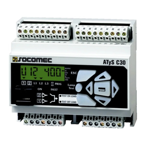
GENERAL PRESENTATION ATyS C20/C30 Product introduction ATYS C20 Control terminals Modular frame Voltage sensing and power supply terminals Keypad ATYS C30 Control terminals Modular frame Voltage sensing and power supply terminals RJ45 terminal Keypad SOCOMEC - Réf. : 532 214 C... -
Page 5: Installation
> Operation • Temperature : -20 °C to +60 °C • Humidity : 80 % at 55 °C 95 % at 40 °C > Consumption 7.5 VA max > Measurement category Cat III SOCOMEC - Réf. : 532 214 C... -
Page 6: Connections
ATyS D10 or D20 remote interface * Only on DC versions. Remote interfaces maximum connection Maximum control cables lenght = 10 m. cable (RJ45) = 3 m. In case of longer distance, insert control relays. SOCOMEC - Réf. : 532 214 C... - Page 7 ATyS D10 or D20 remote interface * Only on DC versions. Remote interfaces maximum connection Maximum control cables lenght = 10 m. cable (RJ45) = 3 m. In case of longer distance, insert control relays. SOCOMEC - Réf. : 532 214 C...
- Page 8 ATyS D10 or D20 remote interface * Only on DC versions. Remote interfaces maximum connection Maximum control cables lenght = 10 m. cable (RJ45) = 3 m. In case of longer distance, insert control relays. SOCOMEC - Réf. : 532 214 C...
- Page 9 In case of longer distance, insert control relays. It might be necessary for some breakers not Remote interfaces maximum connection to set up OMR and OMF timers to 0. cable (RJ45) = 3 m. (refer to programming) SOCOMEC - Réf. : 532 214 C...
- Page 10 Remote interface RJ Remote interface ATyS D10 or D20 Maximum connection RJ45 8/8 connection cable 3 m (1) Only on DC version (2) Refer to programming, Setup, to modify relay state. SOCOMEC - Réf. : 532 214 C...
-
Page 11: Electrical Operation
Controller ATyS CONNECTIONS Electrical operation POWER SUPPLY ATyS C20/C30 integrates 2 power inputs (104-106, 203- AUT position 205), and consider the available source to keep the priority power source product operational. Product supplied when voltage on terminals ≥ 100 Vac... -
Page 12: Visualisation
- switch I state - Changeover switch position control (local or remote) - switch II state * only on ATyS C30. SOFTWARE VERSION Displayed after reset. (3 minutes power off action to allow reset). Version number SOCOMEC - Réf. : 532 214 C... -
Page 13: Operational Modes
PHASES ROTATION CONTROL Function available only on source in case of 3NBL, 4NBL and 41NBL network. If a fault is detected, the source is not indicated as available. displayed according to faulty source. SOCOMEC - Réf. : 532 214 C... -
Page 14: Programming
• Press and hold for 5 s “validation” push button “validation” push button • Step 2: enter code (factory code = 1000) using navigation push buttons • Step 3: press validation push button SOCOMEC - Réf. : 532 214 C... - Page 15 Controller ATyS OPERATION Programming PROGRAMMING MENU ARCHITECTURE SOCOMEC - Réf. : 532 214 C...
- Page 16 400 to 230 V. Press to access first digit (blinking) Press 2X to display 2 (blinking) Press to access second digit (blinking) Press 3X to display 3 (blinking) Press to validate SOCOMEC - Réf. : 532 214 C...
-
Page 17: Annexes
Possible to change the programming code from 0000 to 1000 code 9999 modification * Refer to annexes. (1) It might be necessary for some breakers not to set up OMR and OMF timers to 0. (2 sec.) SOCOMEC - Réf. : 532 214 C... - Page 18 85 % to 98 % Network 2 under voltage threshold hysteresis From 81 95 % to 99 % (> uU) Values definition: % of nominal values Hysteresis values range is limited by thresholds values. SOCOMEC - Réf. : 532 214 C...
- Page 19 95 % to 99 % Network 2 under frequency threshold hysteresis From 80.5 97 % to 99.5 % (> uF) Values definition: % of nominal values Hysteresis values range is limited by thresholds values. SOCOMEC - Réf. : 532 214 C...
- Page 20 0 to 20 s Timer network to main network Cool down Allows generator cooling down period after load’s from 0 to 30 min 4 min Timer retransfer from standby source (generator) to Main source SOCOMEC - Réf. : 532 214 C...
- Page 21 Input 2 Ft1, Ft2, Ft3, Ft4, Pri, Mtf, / / S2A, MAN, CtS, tol, tfl, EJP Input 2 state NO, NC, / Output 1 S1A, S2A, LS, / Output 2 S1A, S2A, LS, / SOCOMEC - Réf. : 532 214 C...
- Page 22 (1) This information is the only considered in case of option configuration. Programming variable Pri is then inhibited. • EJP cycle EJP advice (input 1) EJP transfer (input 2) Start generator Source 1 Source 2 SOCOMEC - Réf. : 532 214 C...
- Page 23 AC II Load shedding output parrallel with the load shedding ouptut relay, position 2 auxiliary contact. This would avoid taking back the load in case of loss of emergency source in emergency position. SOCOMEC - Réf. : 532 214 C...
-
Page 24: Operation
No, press “TEST” Yes, press “validation” TEST OFF LOAD Led “test off load” Led “TEST OFF LOAD” Genset start is blinking is fixed sequence No, press “TEST” Exit: press 5 seconds SOCOMEC - Réf. : 532 214 C... - Page 25 Keypad or remote operation Manual retransfer to validate on keypad. In retransfer sequence from emergency source to priority source, the MRT count down is set to 10 seconds (maximum), unless a lower value has been programmed. SOCOMEC - Réf. : 532 214 C...
-
Page 26: Visualisation
In case of changeover switch on 0 position, priority network voltage is displayed. Navigation in visualisation mode: • Press “up” and “bottom” push buttons to access required parameter • Press “left” and “right” push buttons to navigate in the different menus SOCOMEC - Réf. : 532 214 C... - Page 27 Cool Down Timer network Phase-phase U31 Load shedding* network Phase-neutral voltage V1 network Phase-phase U31 network Network frequency * If selected. All values indicated might not be available according to programmed network. Refer to annexes. SOCOMEC - Réf. : 532 214 C...
-
Page 28: Automatic Sequences
CTS is selected. • source is available or unavailable > Available source Source being within programmed voltage and frequency settings, phases rotation being correct. SOCOMEC - Réf. : 532 214 C... - Page 29 DTT = 0 Transfer I > 0 Count down OMF OMF = 0 Transfer 0 > I I Transfer I > I I Transfer I > I I Go to priority source return automatic sequence SOCOMEC - Réf. : 532 214 C...
- Page 30 Transfer II > I To loss of priority Reset CDT Transfer II > I Count Down source sequence Loss of priority source CDT = 0 Stop generator position 1 Back to priority source control SOCOMEC - Réf. : 532 214 C...
-
Page 31: Troubleshooting Guide
• Verify the number of AC (auxiliary contacts) in the setup menu. It must be in conformity with the number of AC connected • Verify the switch position Error LCD Err XXXX • Send the product back to the manufacturer SOCOMEC - Réf. : 532 214 C... -
Page 32: Annexes
Three phases network without neutral - 3NBL > Three phases network with neutral on source Single phase network with neutral on source - 41 NBL Source 1 Source 2 Source 1 Source 2 Load Load Only single phase loads. SOCOMEC - Réf. : 532 214 C... -
Page 33: Programming And Connections Atys C30
240 V 240 V 240 V 240 V 240 V 240 V * to power supply the product, make a strap between 103 (N) and 104 terminals (input power supply 104-106 on source SOCOMEC - Réf. : 532 214 C... - Page 34 1, Rue de Westhouse - B.P. 10 - F-67235 Benfeld Cedex - FRANCE Tél. + 33 01 45 14 63 90 Fax + 33 01 45 14 63 38 www.socomec.com This document is not a contract. SOCOMEC reserves the right to modify features without prior notice in view of continued improvement.