Table of Contents
Quick Links
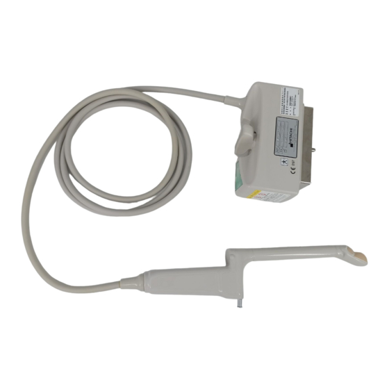
Biplane Transrectal / Vaginal Probe
EUP-CC531S
INSTRUCTION MANUAL
Notes for operators and responsible maintenance personnel
★ Please read through this Instruction Manual carefully prior to use.
★ Keep this Instruction Manual together with the system with care to
make it available anytime.
Tokyo , Japan
Q1E-EP1357-6
© Hitachi, Ltd. 2013,2017. All rights reserved.
0123
Table of Contents

Related Manuals for Hitachi EUP-CC531S


Summary of Contents for Hitachi EUP-CC531S
- Page 1 Notes for operators and responsible maintenance personnel ★ Please read through this Instruction Manual carefully prior to use. ★ Keep this Instruction Manual together with the system with care to make it available anytime. Tokyo , Japan Q1E-EP1357-6 © Hitachi, Ltd. 2013,2017. All rights reserved. 0123...
- Page 2 Hitachi, Ltd. 2-16-1, Higashi-Ueno, Taito-ku, Tokyo,110-0015, Japan +81-3-6284-3668 http://www.hitachi.com/businesses/healthcare/index.html European Representative: Hitachi Medical Systems GmbH Otto-von-Guericke-Ring 3 D-65205 Wiesbaden, Germany EU Importer: Hitachi Medical Systems Europe Holding AG Address: Sumpfstrasse 13 CH-6300 Zug, Switzerland Local Distributor: ( 1 ) Q1E-EP1357...
- Page 3 About this manual This instruction manual contains safety precautions, the inspection, the operation procedure and the reprocessing procedure of EUP-CC531S. Please read this manual thoroughly to ensure the safety operation. If you have any questions concerning the operation of the probe, please contact a service support.
- Page 4 Graphical Symbols for Use in Labeling of Hitachi Ultrasound Probes Some graphical symbols that are used in labeling of Hitachi Ultrasound Probes are compliant with EN980:2008 standard. Refer to the following table about the meanings of them. Explanation of Symbol...
- Page 5 Definition of symbol The following symbol is also used for HITACHI Ultrasound Probes. Location Symbol Definition This instrument complies with Directive 93/42/EEC relating to Probe connector Medical Device and Directive 2011/65/EU relating to RoHS IPX7 mark IPX7 Probe connector See section 1.6.
-
Page 6: Table Of Contents
Use of Sterile Puncture Adapter (EZU-PA5V) ....11 Use of Puncture Guide Fixture (EZU-PA3U) ....12 Display of Needle Guide Line ......13 4 Magnetic Sensor for EUP-CC531S ...... 15 Magnetic Sensor (EZU-RV2S) ......15 Magnetic Sensor (EZU-RV3S) ......19 5 Cleaning, Disinfection and Sterilization .... - Page 7 Sterilization ........... 41 Storage ..........41 7 Maintenance and Safety Inspection ....42 Daily Inspection ........42 Storage ..........42 8 Safety Precautions ........43 9 Specifications ........45 Probe ........... 45 Needle Guides (Option) ........46 Suppliers List .......... 48 Suppliers List for EZU-PA3U ......
-
Page 8: Introduction
Features The Biplane transrectal/vaginal probe EUP-CC531S has convex array electronic scanning. The acoustic output of this probe when connected to Hitachi ultrasound scanner was measured according to the IEC60601-2-37 standard. The table of measured acoustic output data is contained in the operational manual of each Hitachi ultrasound diagnostic scanner. -
Page 9: Intended Use
Intended Use The Biplane transrectal/vaginal probe EUP-CC531S is designed for observation and diagnosis of the following regions mainly by connecting with the HITACHI ultrasound diagnostic scanner. Transrectal/Vaginal Biopsy WARNING Never use the probe for following regions. 1) The heart (Do not contact directly.) -
Page 10: Accessories (Option)
This mechanical compression unit is used for tissue elasticity imaging, by using the balloon attached to the probe that is connected to a Hitachi's digital ultrasound scanner system and electronic scanning ultrasound tomography system. Please refer to the instruction manual of option about the method of handling, cleaning and disinfection of EZU-TEMC1 and EZU-TEBL1. - Page 11 1.5.6 The Magnetic sensor attachment The Magnetic sensor attachment is used for Real-time Virtual Sonography (RVS). By using the attachment, the Magnetic sensor is attached to the probe that is connected to a Hitachi digital ultrasound scanner system. - 4 -...
-
Page 12: Construction
1.5.7 The Spacer for EZU-RV2S The Spacer for EZU-RV2S is used for Real-time Virtual Sonography (RVS) with EZU-RV2S. By using the Spacer, the Magnetic sensor for EZU-RV2S is attached to the Magnetic sensor attachment. CAUTION Sterilization has not been made to the Magnetic sensor attachment and the Spacer for EZU-RV2S shipped from the factory. -
Page 13: Inspection Before Use
Inspection before Use Prior to use, the probe and accessories must be carefully inspected that they are appropriate for use. If you find any damage, do not use them and contact a service support immediately. Inspection for Appropriate Connection 2.1.1 Confirm that the system is correctly operating. Refer to the instruction manual for the ultrasound diagnostic scanner. -
Page 14: Operation Procedure
Operation Procedure Connection and Settings Confirm that the probe is disinfected. In case of using Real-time Virtual Sonography (RVS), confirm that the Magnetic sensor attachment is disinfected and if necessary sterilized. In case of using RVS with EZU-RV2S, confirm that the Spacer for EZU-RV2S is also disinfected and if necessary sterilized. - Page 15 4) Confirm the direction of the probe. The relationship between the direction of the probe and the image is shown in Fig.2. The right-left orientation mark indicates the direction of the index mark of the probe. Sagittal scan Axial scan Orientation mark side Orientation...
-
Page 16: General Instruction
General Instruction 1) In prior to starting the examination, prepare below-mentioned materials. ・ Protective probe cover which is recommended ・ Rubber band ・ Extension tube ・ Three-way cock ・ Syringe ・ Physiological saline 2) Make below-mentioned preparations for the examination. (1) Covering the probe with the protective probe cover from the top of probe is recommended. - Page 17 3) Perform the examination under following procedures. (1) Insert the probe into patient’s body. (2) Pour an adequate volume of physiological saline into the protective probe cover. (3) Perform the examination. Regarding adjustments of image and so on, refer to the operating manual of the scanner to which the probe is connected.
-
Page 18: Use Of Sterile Puncture Adapter (Ezu-Pa5V)
(See Fig.3) 3) Push the other end of the Sterile Puncture Adapter until fix the dents of the Sterile Puncture Adapter to the projection on the probe. (See Fig.4) EZU-PA5V EUP-CC531S Sheath Fig. 3 Fig. 4 - 11 -... -
Page 19: Use Of Puncture Guide Fixture (Ezu-Pa3U)
Use of Puncture Guide Fixture (EZU-PA3U) The process of attaching the Puncture Guide Fixture (EZU-PA3U) to EUP-CC531S is as follows; 1) Attaching the protective probe cover to the probe is recommended. (See “3.2 General Instruction”) 2) Set the Puncture Guide Fixture on the probe as shown in Fig.5, and fix it by tightening the screw 1. -
Page 20: Display Of Needle Guide Line
Display of Needle Guide Line When puncture is to be conducted, the needle guideline can be displayed by dot marks. Operation procedure for displaying the needle guideline on the main unit must be referred to the part of “Needle Guide Line” in the manual of the connected ultrasound scanner. - Page 21 NOTE: In case of switching over depth of the needle guideline on the screen, turn the periphery of “ANGLE key encoder” to switch over depth. WARNING 1) When displaying the needle guideline of the Sterile Puncture Adapter EZU-PA5V, never use the Puncture Guide Fixture EZU-PA3U.
-
Page 22: Magnetic Sensor For Eup-Cc531S
EUP-CC531S, EZU-RV2S and EZU-RV3S. The Magnetic sensor (EZU-RV2S) and the Magnetic sensor (EZU-RV3S) are shown in Fig.7 and Fig.12. The uses of EUP-CC531S with wither of the Magnetic sensors enables the user to perform RVS (Real-time Virtual Sonography). Magnetic Sensor (EZU-RV2S) The Magnetic sensor (EZU-RV2S) as shown in Fig.7 is the Magnetic... - Page 23 a) Attach the Spacer for EZU-RV2S to the Magnetic sensor. b) Insert the Magnetic sensor(EZU-RV2S) into the Magnetic sensor attachment with the correct direction as shown in Fig.8. Projected part Magnetic sensor (EZU-RV2S:black) Spacer for EZU-RV2S Projected part Magnetic sensor attachment Fig.8 How to attach the Magnetic sensor CAUTION 1) Never attach the Magnetic sensor attachment to the probe in...
- Page 24 c) Attach the Magnetic sensor attachment to the probe as shown in Fig.9. Fig.9 How to attach the Magnetic sensor attachment CAUTION Do not put your fingers between the Magnetic sensor attachment and the probe when attaching the Magnetic sensor attachment to the probe.
- Page 25 4.1.2 How to release the Magnetic Sensor The procedure of releasing the Magnetic sensor is as follow. 1) Release the Magnetic sensor attachment from the probe as shown in Fig.10. Fig.10 How to release the Magnetic sensor attachment from the probe 2) Release the Magnetic sensor and the Spacer for EZU-RV2S from the Magnetic sensor attachment as shown in Fig.11.
-
Page 26: Magnetic Sensor (Ezu-Rv3S)
Magnetic Sensor (EZU-RV3S) The Magnetic sensor (EZU-RV3S) as shown in Fig.12 is the Magnetic sensor for EUP-CC531S. Direction mark Magnetic Sensor (white) Fig.12 Magnetic sensor (EZU-RV3S) 4.2.1 How to attach the Magnetic Sensor The procedure of attaching the Magnetic sensor is as follow. - Page 27 CAUTION Never attach the Magnetic sensor attachment to the probe in the incorrect direction, otherwise it may result in false diagnosis. c) Attach the Magnetic sensor attachment to the probe as shown in Fig.14. Fig.14 How to attach the Magnetic sensor attachment CAUTION Do not put your fingers between the Magnetic sensor attachment and the probe when attaching the Magnetic sensor attachment to...
- Page 28 4.2.2 How to release the Magnetic Sensor The procedure of releasing the Magnetic sensor is as follow. 1) Release the Magnetic sensor attachment from the probe as shown in Fig.15. Fig.15 How to release the Magnetic sensor attachment from the probe 2) Release the Magnetic sensor from the Magnetic sensor attachment as shown in Fig.16.
-
Page 29: Cleaning, Disinfection And Sterilization
5 Cleaning, Disinfection and Sterilization The probe and accessory must be reprocessed after each use. Refer to the reprocessing instruction in this chapter. ‐ Particular attention is required when reprocessing probes with lumen. ‐ The probe is delivered unsterile. Prior to the first use, reprocess the probe. - Page 30 (intracavitary (Disinfectant with application) virucidal effect) Cleaning Disinfection Application part contacts (Disinfectant with intracorporeal tissue critical virucidal effect - directly minimum) (operative application) Sterilization According to the intended use, EUP-CC531S is classified as semicritical. - 23 - Q1E-EP1357...
- Page 31 The flowchart of the reprocessing process of this probe is as follows. Point of use (Pre-cleaning) Containment and transportation Manual cleaning and disinfection Manual Cleaning Rinsing after manual cleaning Manual Disinfection Rinsing after manual disinfection Drying Packing Sterilization - 24 - Q1E-EP1357...
-
Page 32: Point Of Use (Pre-Cleaning)
(Pre-cleaning) Pre-cleaning should be done immediately after each use. The procedure is as follows: A) EUP-CC531S 1) Remove the protective cover. 2) Flush the lumen of the probe directly after use with 50 ml deionized water/tap water using a 50 ml syringe (adaptation of the syringe to the Luer inlet of the probe). -
Page 33: Containment And Transportation
Containment and transportation Putting the contaminated equipment into exclusive shock and damage proof container for transportation Containment and is recommended. It is recommended that instruments transportation are reprocessed as soon as possible and not later than 4 hours after usage. Manual cleaning and Manual Cleaning and disinfection disinfection... - Page 34 Prepare the detergent solution in a tank with cold water (please follow the instructions of the detergent manufacturer regarding application, dilution and contact time). A) EUP-CC531S The temperature of the detergent solution should be between 15-30 °C, concentration is 1.6%. Please note the minimum contact time of the detergent in the manufacturer’s instruction.
- Page 35 Rinse the probe and the lumen with running tap water for 1 minute, ensuring that the lumen is rinsed properly. (alternatively: immerse the immersible part of the probe in a tray filled with tap water (see Fig.17) for 5 min. and rinse the lumen of the probe with 50 ml deionized water/tap water 5 times by using the syringe) Visually check the outer surface of the probe for cleanness.
- Page 36 Manual disinfection: A) EUP-CC531S 1) Prepare the disinfectant solution in a tank with cold water (please follow the instructions of the disinfectant manufacturer regarding application, concentration, microbiological efficiency, service life and contact time). 2) Confirm the concentration of the disinfectant before immersing the probe.
-
Page 37: Drying
B) Magnetic sensor attachment and Spacer for EZU-RV2S 1) Prepare the disinfectant solution as stated in the procedure for the probe. 2) Immerse the Magnetic sensor attachment and the Spacer for EZU-RV2S into the disinfectant (see Fig. 17). Set a clock to insure the recommended contact time which is 5 minutes. -
Page 38: Inspection
Inspection Inspect the equipment for any damage such as crack, scratch or deformation. Do not use it if any damage is found. Packaging Packaging Pack the equipment in a sterile barrier such as Polypropylene fleece or transparent package made from Polyethylene film and Tyvek®, and then place it into a tray. -
Page 39: Sterilization
Sterilization Sterilization The probe and accessory can be sterilized using either ethylen oxide gas (EtO) sterilization or plasma sterilization (see table below). Follow the manufacturer's instructions of the sterilizer regarding usage, temperature and sterilization-time. The sterilization method and operating conditions are as follows. Sterilization Method Condition Plasma Sterilization:... - Page 40 The packaging procedure is as follows. 1) Put the probe into TYVEK pouch. Probe TYVEK Pouch Fig.18 Packaging in the pouch 2) Seal the TYVEK Pouch using a heat sealer. Ensure that the seal is complete. Sealed TYVEK Pouch Probe Fig.19 Sealing - 33 - Q1E-EP1357...
-
Page 41: Storage
3) Put the sealed pouch into a tray or plastic mesh wire for sterilization. Tray for Probe in sterilization the Pouch Fig.20 Packaging in a tray Storage Store the equipment in a cool, dustproof and dark, dry space to avoid high temperature, humidity... -
Page 42: Cleaning, Disinfection And Sterilization Of Ezu-Pa3U
6 Cleaning, Disinfection and Sterilization of EZU-PA3U EZU-PA3U must be reprocessed after each use. Refer to the reprocessing instruction in this chapter. EZU-PA3U is delivered unsterile. Prior to the first use, reprocess it. The cavities of the puncture guide fixture require WARNINGS particular attentions during all processes. - Page 43 The flowchart of the reprocessing process of EZU-PA3U is as follows. Point of use (Pre-cleaning) Containment and transportation Manual cleaning and disinfection Manual Cleaning Washer Disinfector (WD) Rinsing after manual Automated Cleaning cleaning Automated Disinfection Manual Disinfection Rinsing after manual disinfection Drying Packing...
-
Page 44: Point Of Use (Pre-Cleaning)
Point of use (Pre-cleaning) Point of use (Pre-cleaning) Pre-cleaning should be done immediately after each use. The procedure is as follows: 1) Remove the EZU-PA3U from the probe. 2) Flush patient’s blood or fluid by tap water from the puncture guide fixture directly after use, until the surface looks visually clean. - Page 45 c) Applicable brush, e.g. REF 09098 (Interlock) d) Two tanks, one for cleaning and one for disinfection - optional: 1 additional tank for rinsing with deionized/tap water e) 50 ml syringe f) Soft, fluff free cloth or single use towel g) Personal protective equipment (gloves, water repellent protective skirt, face protection mask or protective glasses, see also instructions of the manufacturer for the detergent and the...
-
Page 46: Automated Cleaning And Disinfection
(alternatively: immerse them in a tray filled with deionized water/tap water (see Fig.17) for 5 min. and rinse the cavity of the puncture guide fixture with 50 ml tap water. Repeat this 5x.) 7) Visually check the outer surface of the parts of the EZU-PA3U for cleanness. -
Page 47: Drying
1) The parameters of the cleaning and disinfection of the device are as follows: Program step Water (40 l) Dosage (ml/l) Temp. (°C) Time (min) Pre-Rinse Cold water Cleaning Deionized water 5 (0.5%) Rinse Deionized water Disinfection Deionized water 10 (1%) Rinse Deionized water Rinse... -
Page 48: Sterilization
Sterilization Sterilization EZU-PA3U can be sterilized using ethylen oxide gas (EtO) sterilization plasma sterilization, or Steam sterilization. Follow the manufacturer's instructions of the sterilizer regarding usage, temperature and sterilization-time. The sterilization method and operating conditions are as follows. Sterilization Method Condition Plasma Sterilization: STERRAD®... -
Page 49: Maintenance And Safety Inspection
Maintenance and Safety Inspection Daily Inspection 7.1.1 Visually inspect the surface of the probe head, housing, cable and connector for any crack, scratch or denaturalization. If you find any damage, do not use the probe and contact a service support immediately. 7.1.2 Visually inspect the surface of the Magnetic sensor attachment and the Spacer for EZU-RV2S for any crack, deformation or denaturalization. -
Page 50: Safety Precautions
The ultrasound gel attached to the ultrasound scanner as one of accessories is not sterile so never use it with EUP-CC531S. - 43 - Q1E-EP1357... - Page 51 CAUTION Keep the acoustic power low and minimize the ultrasound exposure time for the examination of an early pregnancy. Do not expose the connector to water or other liquids. The connector is not waterproof. Do not hit or drop the probe. The probe is easily damaged by mechanical shock.
-
Page 52: Specifications
Specifications Probe Type : Biplane Transrectal/Vaginal Probe EUP-CC531S Acoustic working frequency Sagittal scan head : 6.5MHz Axial scan head : 6.5MHz Technology : Convex Array Probe Dimensions : See Fig.22 Weight : Approx.0.95kg (Including cable and connector) Scanning angle Sagittal scan head : 100°... -
Page 53: Needle Guides (Option)
Temperature : –10 – +55°C Relative humidity : 10 – 95%(Subject to no condensation) Atmospheric Pressure : 700 – 1060hPa Needle Guides (Option) Needle guideline display of main unit is not accepted change of following two systems. So, if you need for changing of following two systems, please contact a service support. - Page 54 9.2.2 Puncture Guide Fixture EZU-PA3U Type : EZU-PA3U Dimension : See Fig.24 Acceptable needle gauge : 14G to 18G Materials : Bio-compatible allergy free components Classification : MDD classification IIa Cleaning : Applicable detergents are listed in the suppliers list Sterilization method : ETO gas sterilization, Autoclave Operating conditions:...
-
Page 55: Suppliers List
Suppliers List The products listed below are seriously tested and approved for use with the biplane transrectal/vaginal probe EUP-CC531S. Product name manufacturer purpose Cidezyme Johnson & Johnson Enzymatic detergent Meliseptol HBV-Tücher Braun Disinfectant Incidin Liquid Henkel Hygiene GmbH Disinfectant Incidur Spray... -
Page 56: 10 Disposal Of The Probe
10 Disposal of the probe Recycle or dispose of this equipment properly in compliance with the Waste Management and Public Cleansing Law. CAUTION Before disposing of the equipment, disinfect or take other infection-prevention measures. Disposal of the equipment without taking the proper preventative measures can lead to infection. - Page 57 Unit: mm Fig.22 Dimension Diagram of EUP-CC531S - 50 - Q1E-EP1357...
- Page 58 Unit: mm Fig.23 Dimension Diagram with Sterile Puncture Adapter (EZU-PA5V):Option - 51 - Q1E-EP1357...
- Page 59 Unit: mm Fig.24 Dimension Diagram with Puncture Guide Fixture (EZU-PA3U): Option - 52 - Q1E-EP1357...
- Page 60 Unit: mm Fig.25 Dimension Diagram with The Magnetic sensor attachment: Option - 53 - Q1E-EP1357...
- Page 61 - 54 - Q1E-EP1357...