Emerson Rosemount 3051CF Series Reference Manual
Pressure transmitter with foundation fieldbus protocol
Hide thumbs
Also See for Rosemount 3051CF Series:
- Quick start manual (56 pages) ,
- Operating instructions manual (52 pages) ,
- Quick installation manual (20 pages)

Related Manuals for Emerson Rosemount 3051CF Series


Summary of Contents for Emerson Rosemount 3051CF Series
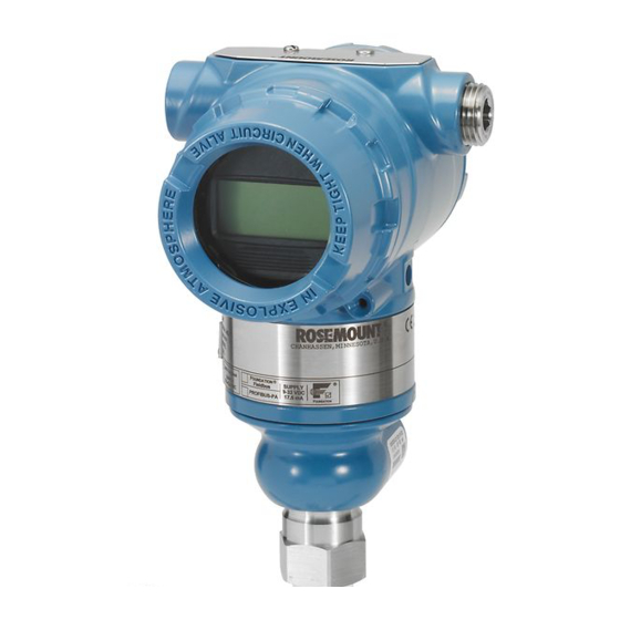
- Page 1 Reference Manual 00809-0100-4774, Rev DB July 2020 ™ Rosemount 3051 Pressure Transmitter ™ with F Fieldbus Protocol OUNDATION...
- Page 2 Avoid contact with the leads and terminals. High voltage that may be present on leads can cause electrical shock. Replacement equipment Replacement equipment or spare parts not approved by Emerson for use as spare parts could reduce the pressure retaining capabilities of the transmitter and may render the instrument dangerous.
- Page 3 The products described in this document are not designed for nuclear-qualified applications. Using non-nuclear qualified products in applications that require nuclear-qualified hardware or products may cause inaccurate readings. For information on Rosemount nuclear-qualified products, contact your local Emerson Sales Representative.
-
Page 5: Table Of Contents
Reference Manual Contents 00809-0100-4774 July 2020 Contents Chapter 1 Introduction......................7 1.1 Using this manual........................7 1.2 Models covered........................... 7 1.3 Host files............................8 1.4 Product recycling/disposal......................8 Chapter 2 Configuration......................9 2.1 Overview............................. 9 2.2 Safety messages.......................... 9 2.3 Device capabilities........................21 2.4 Node address..........................22 2.5 General block information...................... - Page 6 Contents Reference Manual July 2020 00809-0100-4774 5.7 Simulation..........................101 Chapter 6 Troubleshooting....................103 6.1 Overview..........................103 6.2 Safety messages........................103 6.3 Disassembly procedures......................104 6.4 Reassemble..........................106 6.5 Troubleshooting guides......................109 6.6 Troubleshooting and diagnostic messages................111 6.7 Analog input (AI) function block....................115 6.8 Service support........................116 Chapter 7 Advanced pressure diagnostics................
-
Page 7: Chapter 1 Introduction
• Rosemount 3051L Liquid Level Transmitter — Measures level and specific gravity up to 300 psi (20.7 bar). • Rosemount 3051CF Series Flowmeter Measures flow in line sizes from ½-in. (15 mm) to 96-in. (2400 mm). — Note ® For transmitter with 4-20 mA HART... -
Page 8: Host Files
(DD) or Device Type Manager (DTM ) file revision for this device. The device descriptor can be found on Fieldbus.org. The DTM can be found at Emerson.com. The current release of the Rosemount 3051 with Foundation Fieldbus protocol is device revision 8. This manual is for revision 8. -
Page 9: Chapter 2 Configuration
Reference Manual Configuration 00809-0100-4774 July 2020 Configuration Overview This section contains information on commissioning and tasks that should be performed on the bench prior to installation, as well as tasks performed after installation. Safety messages Procedures and instructions in this section may require special precautions to ensure the safety of the personnel performing the operations. - Page 10 00809-0100-4774 WARNING Replacement parts Replacement equipment or spare parts not approved by Emerson for use as spare parts could reduce the pressure retaining capabilities of the transmitter and may render the instrument dangerous. Use only bolts supplied or sold by Emerson as spare parts.
- Page 11 Reference Manual Configuration 00809-0100-4774 July 2020 2.2.3 Basic organization Device information and tasks are organized into three different menu tree branches. They are Overview, Configure, and Service Tools. Information and tasks may be resident in more than a single branch of the menu tree. The device menu tree is the landing screen for the Handheld user interface.
- Page 12 Configuration Reference Manual July 2020 00809-0100-4774 Figure 2-2: Configure Device Alerts-Single Screen A. Screen name B. Configure Suppressed Alerts button C. Status signal categories D. Alert check boxes On this PC-based configuration screen, alert configuration for all four alert categories is performed on a single screen.
- Page 13 Reference Manual Configuration 00809-0100-4774 July 2020 2.2.5 Overview The Overview branch of the menu tree provides device information and single keystroke shortcuts to view variables and device status, access device diagnostics, and perform basic calibration functions. The Overview screen is the landing screen for PC-based user interfaces.
- Page 14 Manual setup also allows you to edit specific parameters without needing to ™ step through all the setup steps. If you are not familiar with a specific task, Emerson recommends guided setup so task steps are done in the correct order and all needed steps are performed.
- Page 15 Note The NE107 specification allows a single alert to be included in multiple categories. As a general practice, Emerson does not recommend this as alarm management can become needlessly complex. You can suppress NE107 alerts. If you configure an alert to reside in multiple categories, you can suppress it in some categories, but not others.
- Page 16 Configuration Reference Manual July 2020 00809-0100-4774 2.2.7 Service tools Black text - Navigation selection available (Text) - Name of selection used on parent menu screen to access this screen Green text - Automated methods The Service Tools branch of the menu tree allows you to perform typical device maintenance tasks, simulate alerts and parameters, and perform some configuration resets to return devices to as-manufactured settings.
- Page 17 Reference Manual Configuration 00809-0100-4774 July 2020 Figure 2-9: Complete Menu Tree Black text - Navigation selection available (Text) - Name of selection used on parent menu screen to access this screen Green text - Automated methods Reference Manual...
- Page 18 Configuration Reference Manual July 2020 00809-0100-4774 Figure 2-10: Partial Menu Tree Black text - Navigation selection available (Text) - Name of selection used on parent menu screen to access this screen Green text - Automated methods Red text - Configuration task numbers from configuration flow chart 2.2.8 Navigation To navigate, click the navigation button labeled with the task you wish to perform.
- Page 19 Expert users will use classic view to review all block parameters, and to perform some configuration or service tasks. Emerson does not recommend classic view to anyone who ™...
- Page 20 Analog Input Block 1 linked to the primary variable of the transducer block and scheduled to run. This is necessary to configure signal conditioning and scaling. Emerson encourages you to use Analog Input Block 1 for the primary variable when configuring control strategies.
-
Page 21: Device Capabilities
Reference Manual Configuration 00809-0100-4774 July 2020 Device capabilities 2.3.1 Link active scheduler (LAS) The transmitter can be designated to act as the backup LAS in the event that the LAS is disconnected from the segment. As the backup LAS, the Rosemount 3051 will take over the management of communications until the host is restored. -
Page 22: Node Address
Configuration Reference Manual July 2020 00809-0100-4774 Table 2-2: (continued) Block Time (in ms) Integrator Output splitter Control selector Node address ™ The transmitter is shipped at a temporary (248) address. This enables F OUNDATION Fieldbus host systems to automatically recognize the device and move it to a permanent address. - Page 23 Reference Manual Configuration 00809-0100-4774 July 2020 Note Typically, instrument personnel configure the channel, Set XD_Scale, Set L_Type, and sometimes Set Out_Scale. The control systems configuration engineer configures other AI block parameters, block links, and schedule. Input selector block ™ You can use the input selector (ISEL) function block to select the first good, Hot Backup maximum, minimum, or average of as many as eight input values and place it at the output.
- Page 24 Permitted modes You can prevent unauthorized changes to the operating mode of a block. To do this, configure MODE_BLK.PERMITTED to allow only the desired operating modes. Emerson recommends always selecting OOS as one of the permitted modes. Rosemount 3051...
- Page 25 Reference Manual Configuration 00809-0100-4774 July 2020 Types of modes For procedures described in this manual, it is helpful to understand the following modes. AUTO The functions performed by the block will execute. If the block has any outputs, these will continue to update.
-
Page 26: Resource Block
Configuration Reference Manual July 2020 00809-0100-4774 2.5.4 Simulation Simulation is the functionality of the AI block. There are two ways to simulate values as follows: Procedure 1. Change the mode of the block to Manual and adjust the output value. 2. - Page 27 Reference Manual Configuration 00809-0100-4774 July 2020 normally, updating inputs and outputs and executing algorithms. When the condition is cleared, an alert is generated with a priority that corresponds to the WRITE_PRI parameter. The FEATURE_SEL parameter enables you to select any one of the following: a hardware write lock, a software write lock, or no write lock capability.
- Page 28 Configuration Reference Manual July 2020 00809-0100-4774 2. The status conditions are then mapped into four status signals that can be used for annunciation on the segment to the host. 3. Before annunciation, a check is made to determine if you have masked any alert parameters.
- Page 29 Reference Manual Configuration 00809-0100-4774 July 2020 Figure 2-12: NE 107 Status Signal to Plantweb Alert Mapping The alert priority enumeration value Alerts have priorities that determine if they occur and where and how they are annunciated. ™ NE107 status signals and Plantweb alerts use the same priorities and annunciate the same ways.
- Page 30 Configuration Reference Manual July 2020 00809-0100-4774 NE107 alerts overview NE107 alert parameters NE107 has four alert status signals. They are in order from highest to lowest priority: 1. FD_FAIL_ACTIVE 2. FD_OFFSPEC_ACTIVE 3. FD_MAINT_ACTIVE 4. FD_CHECK_ACTIVE You can configure any of the eight alert conditions to annunciate as any of the four status signals.
- Page 31 Reference Manual Configuration 00809-0100-4774 July 2020 A FD_CHECK_ACTIVE status signal indicates a transducer block is not in “Auto” mode. This may be due to configuration or maintenance activities. Mapping alert conditions You can map any of the alert conditions into any of the NE107 status signals using the following parameters.
- Page 32 The eight alert conditions are factory configured to annunciate as one of the three specific alert parameters. Plantweb alert parameter conditions and factory defaults ™ Emerson ships devices from the factory with all applicable Plantweb alerts enabled. The alert conditions reported in each parameter are: 1. FAILED_ALM a.
-
Page 33: Basic Device Setup
Reference Manual Configuration 00809-0100-4774 July 2020 condition exists. Check the device to determine the type of abnormal condition and recommended actions to resolve it. Plantweb alert priorities ™ ™ Configure Plantweb alert priorities in DeltaV . Plantweb alerts can have any of 16 different condition prioritiesl, ranging from the lowest priority of 0 to the highest priority of 15. - Page 34 Configuration Reference Manual July 2020 00809-0100-4774 Figure 2-13: Basic Configuration Menu Tree (Calibration) (Overview ) Primary Value Pressure Sensor Trim Calibration Sensor Limits Device Information Restore Factory Calibration Locate Device Last Calibration Points Scale Gauges Calibration Details (Device Information ) (Materials of Construction ) Identification (1) Sensor...
- Page 35 Reference Manual Configuration 00809-0100-4774 July 2020 7. Set damping: PRIMARY_VALUE_DAMPING. 8. Set up LCD display. 9. Review transmitter configuration. 10. Set switches and software write lock. Prerequisites Figure 2-13 to graphically view the step by step process for basic device configuration. Before beginning configuration, you may need to verify the device tag or deactivate hardware and software write protection on the transmitter.
- Page 36 Configuration Reference Manual July 2020 00809-0100-4774 • To use guided setup: a. Navigate to Configure > Guided Setup. b. Select AI Block Unit Setup. Note Guided setup will automatically go through each step in the proper order. • To use manual setup: a.
- Page 37 Reference Manual Configuration 00809-0100-4774 July 2020 a) Select the XD_SCALE_UNITS from the dropdown menu. b) Enter the XD_SCALE 0% point. This may be elevated or suppressed for level applications. c) Enter the XD_SCALE 100% point. This may be elevated or suppressed for level applications. d) If L_TYPE is Direct, you may place the AI block in AUTO mode to return the device to service.
- Page 38 Configuration Reference Manual July 2020 00809-0100-4774 • To use guided setup: — Navigate to Configure > Guided Setup, and select Local Display Setup. Note Guided setup will automatically go through each step in the proper order. — Check the box next to each parameter to be displayed to a maximum of four parameters.
-
Page 39: Analog Input (Ai) Function Block
Reference Manual Configuration 00809-0100-4774 July 2020 Analog input (AI) function block 2.8.1 Configure the AI block Note Always check and reconcile function block configuration (with the exception of resource and transducer blocks) after commissioning the transmitter to the control host. You may not save function block configuration, including AI blocks, made prior to device commissioning in the control host to the control host database during the commissioning process. - Page 40 Configuration Reference Manual July 2020 00809-0100-4774 CHANNEL Select the channel that corresponds to the desired sensor measurement. The transmitter measures both pressure (channel 1) and sensor temperature (channel 2). Table 2-4: I/O Channel Definitions Channel number Channel description Pressure in AI.XD_SCALE units Sensor temperature in AI.XD_SCALE units Mean Standard deviation...
- Page 41 Reference Manual Configuration 00809-0100-4774 July 2020 L_TYPE is indirect When an inferred measurement is made based on the sensor measurement, set the XD_SCALE to represent the operating range that the sensor will see in the process. Determine the inferred measurement values that correspond to the XD_SCALE 0 and 100% points and set these for the OUT_SCALE.
- Page 42 Configuration Reference Manual July 2020 00809-0100-4774 Figure 2-14: Analog Input PV_FTIME Filtering Diagram A. OUT (mode in man) B. OUT (mode in auto) C. PV D. 63% of change E. FIELD_VAL F. PV_FTIME G. Time (seconds) Low cutoff When the converted input value is below the limit specified by the LOW_CUT parameter, and the low cutoff I/O option (IO_OPTS) is enabled (True), a value of zero is used for the converted value (PV).
- Page 43 Reference Manual Configuration 00809-0100-4774 July 2020 In order to avoid alarm chattering when the variable is oscillating around the alarm limit, an alarm hysteresis in percent of the PV span can be set using the ALARM_HYS parameter. The priority of each alarm is set in the following parameters: •...
-
Page 44: Advanced Device Setup
Configuration Reference Manual July 2020 00809-0100-4774 ALARM_TYPE ALARM_TYPE allows one or more of the process alarm conditions detected by the AI function block to be used in setting its OUT_D parameter. OUT_D OUT_D is the discrete output of the AI function block based on the detection of process alarm condition(s). - Page 45 Reference Manual Configuration 00809-0100-4774 July 2020 control system Analog Input Block configuration screens. Consult your control system documentation for more information. Figure 2-15: Process Variables Screen The change damping button shown in Figure 2-15 above starts an automated procedure called a Method which allows damping to be changed. Procedure 1.
- Page 46 Configuration Reference Manual July 2020 00809-0100-4774 Figure 2-16: Overview Screen The Scale Gauges button shown in Figure 2-16 above starts an automated procedure called a method which allows you to change the scaling on the gauge. 2.9.4 Local display (LCD display) Note Set up the local display in the LCD display transducer block.
- Page 47 Reference Manual Configuration 00809-0100-4774 July 2020 Figure 2-17: Local Display Basic Configuration Screen The screen shown in Figure 2-17 above allows you to select parameters to be displayed on the LCD display by checking the box next to each parameter. Select the Advanced Configuration button to access more display configuration options.
- Page 48 Configuration Reference Manual July 2020 00809-0100-4774 The screen shown in Figure 2-18 above provides the capability to define parameters for display beyond those defined in Basic Configuration. Configuration fields for Parameters 2, 3, and 4 are provided but not shown in the image. Note You can configure the LCD display to display a mix of basic and advanced parameters.
- Page 49 You can assign alerts to more than one category by selecting the same alert check box in multiple categories. Emerson does not recommend this, as alarms can proliferate, increasing the complexity of alarm management and delaying corrective action.
- Page 50 Configuration Reference Manual July 2020 00809-0100-4774 Figure 2-20: Configure Device Alerts Screen A. Screen name B. Configure Suppressed Alerts button C. Status signal categories D. Alert check boxes The screen shown in Figure 2-20 is where you can assign alerts by selecting the box next to the desired alert in the desired category.
- Page 51 Reference Manual Configuration 00809-0100-4774 July 2020 Figure 2-21: Suppressed Device Alerts Screen A. Screen name B. Status signal categories C. Suppress alert check boxes The screen shown in Figure 2-21 is where you can suppress alerts by checking the box next to the alert to be suppressed.
- Page 52 Configuration Reference Manual July 2020 00809-0100-4774 Figure 2-22: Enable/Disable Alert Simulation Screen A. Enable/Disable Alert suppression button B. Check boxes to activate/deactivate simulation of specific alerts The screen shown in Figure 2-22 above enables/disables overall alert simulation capability and allows individual alerts to be selected for simulation. The sequence of steps to enable alert simulation is: Procedure 1.
- Page 53 The minimum monitoring time is one minute; three minutes is a typical monitoring cycle. ™ 2. For Bypass Verification, select Yes or No. Emerson recommends verification for applications where SPM monitoring has not been done previously, or where process changes may cause significant changes in mean or standard deviation.
- Page 54 Configuration Reference Manual July 2020 00809-0100-4774 The screen shown in Figure 2-23 above allows full SPM configuration, configuration edits, enabling and disabling monitoring, and provides an indication of the status of the monitored variable. 2.9.9 Write lock Note Perform write lock functions in the Resource Block. For block oriented user interfaces, perform write lock management in the Resource Block.
- Page 55 Reference Manual Configuration 00809-0100-4774 July 2020 Figure 2-24: Security and Simulation Display Screen A. Hardware locked B. Hardware lock switch C. Hardware not locked D. Enable E. Disable F. Simulate enable / disable switch The screen shown in Figure 2-24 above allows you to see if the device has simulation active, to see if any form of write lock is active, and to configure hardware and software write lock.
- Page 56 Configuration Reference Manual July 2020 00809-0100-4774 Rosemount 3051...
-
Page 57: Chapter 3 Hardware Installation
Overview The information in this section covers installation considerations for the Rosemount 3051 ™ with F Fieldbus protocols. Emerson ships a Quick Start Guide with every OUNDATION transmitter to describe the recommended pipe fitting and wiring procedures for initial installation. -
Page 58: Installation Considerations
00809-0100-4774 WARNING Spare parts Replacement equipment or spare parts not approved by Emerson for use as spare parts could reduce the pressure retaining capabilities of the transmitter and may render the instrument dangerous. Use only bolts supplied or sold by Emerson as spare parts. -
Page 59: Tagging
Reference Manual Hardware installation 00809-0100-4774 July 2020 185 °F (–40 to 85 °C). Mount the transmitter so that it is not susceptible to vibration and mechanical shock and does not have external contact with corrosive materials. Tagging 3.4.1 Commissioning tag The transmitter is supplied with a removable commissioning tag that contains both the Device ID (the unique code that identifies a particular device in the absence of a device tag) and a space to record the device tag (PD_TAG) (the operational identification for the... -
Page 60: Installation Procedures
Hardware installation Reference Manual July 2020 00809-0100-4774 Installation procedures 3.5.1 Mount the transmitter For dimensional drawing information refer to the Dimensional Drawings section of the Rosemount 3051 Product Data Sheet. Process flange orientation Complete the following steps to mount the process flanges. Procedure 1. - Page 61 Reference Manual Hardware installation 00809-0100-4774 July 2020 Figure 3-2: Housing Rotation A. Housing rotation set screw (5/64-in.) Electronics housing clearance Mount the transmitter so the terminal side is accessible. Clearance of 0.75-in. (19 mm) is required for cover removal. Use a conduit plug in the unused conduit opening. Three inches of clearance is required for cover removal if a meter is installed.
- Page 62 Hardware installation Reference Manual July 2020 00809-0100-4774 Figure 3-3: Mounting Bracket Option Code B4 A. 5/16 x 1½-in. bolts for panel mounting (not supplied) B. ⅜-16 x 1¼-in. bolts for mounting to transmitter Dimensions are in inches (millimeters). 1. The last digit in the FS93_ head marking may be any letter between A and M. Figure 3-4: Mounting Bracket Option Codes B1, B7, and BA Dimensions are in inches (millimeters).
- Page 63 Bolt installation. Stainless steel bolts supplied by Emerson are coated with a lubricant to ease installation. Carbon steel bolts do not require lubrication. Do not apply additional lubricant when installing either type of bolt. Bolts supplied by Emerson are identified by their head markings.
- Page 64 Use the following bolt installation procedure: WARNING Spare parts Replacement equipment or spare parts not approved by Emerson for use as spare parts could reduce the pressure retaining capabilities of the transmitter and may render the instrument dangerous. Use only bolts supplied or sold by Emerson as spare parts.
- Page 65 Reference Manual Hardware installation 00809-0100-4774 July 2020 1.50 (38) × 4 1.50 (38) × 2 1.75 (44) × 4 1.75 (44) × 4 A. Drain/vent Dimensions are in inches (millimeters). For gage and absolute transmitters: 150 (38) × 2 Figure 3-9: Mounting Bolts and Bolt Configurations for Coplanar Flange Transmitter with flange bolts Transmitter with flange adapters and flange/adapter bolts...
- Page 66 Hardware installation Reference Manual July 2020 00809-0100-4774 Description Size in. (mm) Differential pressure Flange bolts 1.75 (44) 2.88 (73) Gage/absolute pressure Flange bolts 1.75 (44) Flange/adapter bolts 2.88 (73) Rosemount 3051T Transmitters are direct mount and do not require bolts for process connection.
- Page 67 Reference Manual Hardware installation 00809-0100-4774 July 2020 Figure 3-10: Installation Examples Liquid service Gas service Steam service A. Drain/vent valves B. Flow Best practices The piping between the process and the transmitter must accurately transfer the pressure to obtain accurate measurements. There are five possible sources of error: pressure transfer, leaks, friction loss (particularly if purging is used), trapped gas in a liquid line, liquid in a gas line, and density variations between the legs.
- Page 68 Hardware installation Reference Manual July 2020 00809-0100-4774 • Use impulse piping large enough to avoid friction effects and blockage. • Vent all gas from liquid piping legs. • When using a sealing fluid, fill both piping legs to the same level. •...
- Page 69 Reference Manual Hardware installation 00809-0100-4774 July 2020 O-rings The two styles of Rosemount flange adapters (Rosemount 1151 and 3051/2051/2024/ 3095) each require a unique O-ring. Use only the O-ring designed for the corresponding flange adapter. WARNING Failure to install proper flange adapter O-rings may cause process leaks, which can result in death or serious injury.
- Page 70 Hardware installation Reference Manual July 2020 00809-0100-4774 3.5.4 Inline process connection Inline gage transmitter orientation CAUTION Erroneous pressure values The transmitter may output erroneous pressure values. Do not interfere or block the atmospheric reference port. The low side pressure port on the inline gage transmitter is located in the neck of the transmitter, behind the housing.
-
Page 71: Rosemount 305, 306, And 304 Manifolds
Reference Manual Hardware installation 00809-0100-4774 July 2020 Figure 3-12: Inline Gage A. Sensor module B. Process connection Rosemount 305, 306, and 304 manifolds The Rosemount 305 integral manifold mounts directly to the transmitter and is available in two styles: traditional and coplanar. The traditional Rosemount 305 integral manifold can be mounted to most primary elements with mounting adapters in the market today. - Page 72 Hardware installation Reference Manual July 2020 00809-0100-4774 Figure 3-13: Manifolds A. Rosemount 3051C and 304 conventional B. Rosemount 3051C and 305 integral coplanar C. Rosemount 3051C and 305 integral traditional D. Rosemount 3051T and 306 in-line The Rosemount 304 conventional manifold combines a traditional flange and manifold that can be mounted to most primary elements.
- Page 73 Reference Manual Hardware installation 00809-0100-4774 July 2020 When fully tightened, the bolts should extend through the top of the sensor module housing. 3. If you have replaced the PTFE sensor module O-rings, re-tighten the flange bolts after installation to compensate for cold flow of the O-rings. 3.6.2 Install Rosemount 306 integral manifold The Rosemount 306 Manifold is for use only with in-line pressure transmitters such as the...
- Page 74 Hardware installation Reference Manual July 2020 00809-0100-4774 A. Drain/vent valve B. Isolate (open) C. Equalize (closed) D. Process E. Isolate (open) F. Drain/vent valve Procedure 1. To zero trim the transmitter, close the isolate valve on the low side (downstream) side of the transmitter.
- Page 75 Reference Manual Hardware installation 00809-0100-4774 July 2020 A. Drain/vent valve B. Isolate (open) C. Equalize (closed) D. Process E. Isolate (closed) F. Drain/vent valve 4. Finally, to return the transmitter to service, open the low side isolate valve. A. Drain/vent valve B.
- Page 76 Hardware installation Reference Manual July 2020 00809-0100-4774 A. Isolate (open) B. Process C. Equalize (closed) D. Equalize (closed) E. Drain vent (closed) F. Process G. Isolate (open) Procedure 1. To zero trim the transmitter, first close the isolate valve on the low pressure (downstream) side of the transmitter and the vent valve.
- Page 77 Reference Manual Hardware installation 00809-0100-4774 July 2020 A. Isolate (open) B. Process C. Equalize (open) D. Equalize (closed) E. Drain vent (closed) F. Process G. Isolate (closed) 3. Open the equalize valve on the low pressure (downstream) side of the transmitter. The manifold is now in the proper configuration for zeroing the transmitter.
- Page 78 Hardware installation Reference Manual July 2020 00809-0100-4774 A. Isolate (open) B. Process C. Equalize (open) D. Equalize (closed) E. Drain vent (closed) F. Process G. Isolate (closed) 5. Close the equalize valve on the high pressure (upstream) side. A. Isolate (open) B.
- Page 79 Reference Manual Hardware installation 00809-0100-4774 July 2020 A. Isolate (open) B. Process C. Equalize (closed) D. Equalize (closed) E. Drain vent (closed) F. Process G. Isolate (open) In-line transmitters Two-valve and block and bleed style manifolds Isolating the transmitter In normal operation, the isolate (block) valve between the process port and transmitter will be open and the test/vent valve will be closed.
- Page 80 Hardware installation Reference Manual July 2020 00809-0100-4774 A. Transmitter B. Vent (closed) C. Isolate D. Process (closed) 2. To bring the transmitter to atmospheric pressure, open the vent valve or bleed screw. A. Transmitter B. Vent (open) C. Isolate D. Process (closed) Note A ¼-in (6.35 mm).
- Page 81 Reference Manual Hardware installation 00809-0100-4774 July 2020 A. Transmitter B. Vent (closed) C. Isolate D. Process (open) Adjust valve packing Over time, the packing material inside a Rosemount manifold may require adjustment in order to continue to provide proper pressure retention. Not all Rosemount manifolds have this adjustment capability.
- Page 82 Hardware installation Reference Manual July 2020 00809-0100-4774 Figure 3-14: Valve Components A. Bonnet B. Stem C. Packing D. Ball/tip E. Packing adjuster F. Jam nut G. Packing follower Rosemount 3051...
-
Page 83: Chapter 4 Electrical Installation
Reference Manual Electrical installation 00809-0100-4774 July 2020 Electrical installation Overview The information in this section covers installation considerations for the Rosemount 3051 Transmitter. A Quick Start Guide is shipped with every transmitter to describe pipe-fitting, wiring procedures, and basic configuration for initial installation. Note For transmitter disassembly and reassembly, refer to Disassembly procedures... -
Page 84: Lcd Display
4. Re-insert screws. 5. Reattach transmitter housing cover. Emerson recommends that you tighten the cover until there is no gap between the cover and housing to comply with explosion proof requirements. 6. Re-attach power and return loop to automatic control. - Page 85 3. Slide the Security and Simulate switches into the preferred position. 4. Reattach transmitter housing cover; Emerson recommends tightening the cover until there is no gap between the cover and housing to comply with explosion proof requirements.
-
Page 86: Electrical Considerations
Electrical installation Reference Manual July 2020 00809-0100-4774 simulate variables and/or alerts and alarms, move the Simulate switch to the Enable position and enable the software through the host. To disable simulation, move the Simulate switch to the Disable psoition or disable the Software Simulate parameter through the host. -
Page 87: Wiring
Rosemount 3051 terminal block. The terminals are not polarity sensitive. The transmitter requires 9–32 Vdc to operate. Emerson recommends Type A FOUNDATION Fieldbus wiring 18 awg twisted shielded pair. Do not exceed 5000 ft. (1500 m) total segment length. - Page 88 Note Emerson does not recommend using a pin or ferrule wire terminal, as the connection may be more susceptible to loosening over time or under vibration. 3. Plug and seal the unused conduit connection on the transmitter housing to avoid moisture accumulation in the terminal side.
- Page 89 Improper grounding is the most frequent cause of poor segment communications. 4. Replace the housing cover. Emerson recommends tightening the cover until there is no gap between the cover and the housing. 5. Plug and seal unused conduit connections. Transmitter case grounding Always ground the transmitter case in accordance with national and local electrical codes.
- Page 90 Electrical installation Reference Manual July 2020 00809-0100-4774 ™ ). The ground connection screw is standard on all Rosemount transmitters. Refer Figure 4-4. • External ground connection: The external ground connection is located on the exterior of the transmitter housing. Refer to Figure 4-5.
- Page 91 Reference Manual Electrical installation 00809-0100-4774 July 2020 Transient protection terminal block grounding The transmitter can withstand electrical transients of the energy level usually encountered in static discharges or induced switching transients. However, high-energy transients, such as those induced in wiring from nearby lightning strikes, can damage the transmitter. You can order the transient protection terminal block as an installed option (Option Code T1) or as a spare part to retrofit existing transmitters in the field.
- Page 92 Electrical installation Reference Manual July 2020 00809-0100-4774 Rosemount 3051...
-
Page 93: Operation And Maintenance
™ that a host or configuration tool support these features. For DeltaV users, the DD can be found at Emerson.com/DeltaV. The information in this section will describe how to use methods in a general fashion. Safety messages Procedures and instructions in this section may require special precautions to ensure the safety of personnel performing the operations. -
Page 94: Calibration Overview
Electrical shock can result in death or serious injury. Spare parts Replacement equipment or spare parts not approved by Emerson for use as spare parts could reduce the pressure retaining capabilities of the transmitter and may render the instrument dangerous. - Page 95 Reference Manual Operation and maintenance 00809-0100-4774 July 2020 For transmitters that are field installed, the manifolds discussed in Manifold operation allow the differential transmitter to be zeroed using the zero trim function. Manifold operation discusses both three-valve and five-valve manifolds. This field calibration eliminates any pressure offsets caused by mounting effects (head effect of the oil fill) and static pressure effects of the process.
- Page 96 Operation and maintenance Reference Manual July 2020 00809-0100-4774 Line pressure 500 psig (34,5 bar) 3. Calculate total probable error (TPE). TPE = = 0.105% of span Where: Reference Accuracy = ± 0.04% of span Ambient Temperature Effect = Span Static Pressure Effect Zero static pressure effect removed by zero trimming at line pressure.
-
Page 97: Trim The Pressure Signal
Reference Manual Operation and maintenance 00809-0100-4774 July 2020 High trim value HT = (URV – [S/100 ×P/1000 × LRV]) Where: HT = Corrected high trim value URV = Upper range value Span shift per specification (as a percent of reading) Static Line Pressure in psi In this example: URV =... - Page 98 Operation and maintenance Reference Manual July 2020 00809-0100-4774 a low trim within the sensor trim function. The low trim function provides an offset correction similar to the zero trim function, but it does not require zero-based input. Upper and lower sensor trim is a two-point sensor calibration where two end-point pressures are applied and all output is linearized between them;...
- Page 99 Reference Manual Operation and maintenance 00809-0100-4774 July 2020 Navigate to the Sensor Trim screen and click the button for the type of trim desired. An automated procedure called a Method guides you through the desired trim procedure. The automated procedure for upper and lower sensor trims includes steps for documenting pressure, units, date, and name of person performing the trim and physical location where the trim was performed.
-
Page 100: Status
Operation and maintenance Reference Manual July 2020 00809-0100-4774 Procedure Select Lower Sensor Trim. Note Select pressure points so that lower and upper values are equal to or outside the expected process operation range. Status ™ Along with the measured or calculated PV value, every F Fieldbus block passes OUNDATION an additional parameter called STATUS. -
Page 101: Simulation
Reference Manual Operation and maintenance 00809-0100-4774 July 2020 • Run - Default State • Resource - Not Used ™ • Defaults - Sets all device parameters to F Fieldbus default values OUNDATION • Processor - Does a software reset of the CPU Simulation Simulate replaces the channel value coming from the Sensor Transducer Block. - Page 102 Operation and maintenance Reference Manual July 2020 00809-0100-4774 Rosemount 3051...
-
Page 103: Chapter 6 Troubleshooting
Reference Manual Troubleshooting 00809-0100-4774 July 2020 Troubleshooting Overview This section provides summarized troubleshooting suggestions for the most common operating problems. This section contains Rosemount 3051 Pressure Transmitter with ™ Fieldbus Protocol troubleshooting information only. OUNDATION Disassembly and reassembly procedures can be found in Disassembly procedures Reassemble. -
Page 104: Disassembly Procedures
Troubleshooting Reference Manual July 2020 00809-0100-4774 WARNING Electrical shock Electrical shock can result in death or serious injury. Avoid contact with the leads and terminals. High voltage that may be present on leads can cause electrical shock. CAUTION Static electricity Static electricity can damage sensitive components. - Page 105 Reference Manual Troubleshooting 00809-0100-4774 July 2020 7. Clean isolating diaphragms with a soft rag and a mild cleaning solution, and rinse with clear water. 8. For the Rosemount 3051C, whenever you remove the process flange or flange adapters, visually inspect the PTFE O-rings. Replace the O-rings if they show any signs of damage, such as nicks or cuts.
-
Page 106: Reassemble
Troubleshooting Reference Manual July 2020 00809-0100-4774 Note Do not remove the housing until after you tuck the cable connector completely inside of the internal black cap. The black cap protects the ribbon cable from damage that can occur when you rotate the housing. 3. - Page 107 Troubleshooting 00809-0100-4774 July 2020 4. Replace the housing cover. Emerson recommends tightening the cover until there is no gap between the cover and the housing. 6.4.2 Install terminal block Complete the following steps to reinstall the terminal block into the transmitter.
- Page 108 Troubleshooting Reference Manual July 2020 00809-0100-4774 b. Hold the flange adapters and adapter O-rings in place while installing (in the desired of the four possible process connection spacing configurations) using four 2.88-in. bolts to mount securely to the coplanar flange. For gage pressure configurations, use two 2.88-inch bolts and two 1.75-in.
-
Page 109: Troubleshooting Guides
3. If you can identify the problem, perform the Recommended Action in Device does not show up on segment. 4. If the problem persists, contact your local Emerson representative. Device does not stay on segment Steps to identify cause Check segment Recommended actions 1. - Page 110 Troubleshooting Reference Manual July 2020 00809-0100-4774 Recommended actions 1. Ensure the device is connected to the segment. 2. Check voltage at terminals. It should be 9 - 32 Vdc. 3. Check to ensure the device is drawing current. It should be approximately 17 Pontential cause Segment problems Recommended action...
-
Page 111: Troubleshooting And Diagnostic Messages
Reference Manual Troubleshooting 00809-0100-4774 July 2020 4. Check for corrosion or moisture on terminals. 5. Check for bad power supply. 6. Check for electrically noisy equipment attached to the instrument ground. Electronics failing Recommended actions 1. Tighten electronics board. 2. Replace electronics. Other Recommended action Check for water in the terminal housing. - Page 112 Troubleshooting Reference Manual July 2020 00809-0100-4774 Default configuration Enabled LCD display message ^^^^FAIL SENSOR Associated status bits 0x20000000 6.6.3 Electronics failure ™ NE107 and Plantweb alert: Failure A failure has occurred in the electronics board. Recommended action • Replace electronics board. Default configuration Enabled LCD display message...
- Page 113 Reference Manual Troubleshooting 00809-0100-4774 July 2020 Associated status bits 0x00100000 6.6.5 Sensor temperature out of limits ™ NE107 alert: Offspec; Plantweb alert: Maintenance The sensor temperature is outside the transmitter's operating range. Recommended actions • Check the process and ambient temperature conditions are within -85 to 194 °F (-65 to 90 °C).
- Page 114 Troubleshooting Reference Manual July 2020 00809-0100-4774 6.6.7 Variation change detected ™ NE107 and Plantweb alert: Maintenance The statistical process monitor has detected either a mean variation or high or low dynamics in the process. Recommended actions • Check the statistical process monitor status in the diagnostics transducer block. •...
-
Page 115: Analog Input (Ai) Function Block
Reference Manual Troubleshooting 00809-0100-4774 July 2020 • If no transducer block is under maintenance, the follow site procedures to change the affected transducer block's Actual Mode to Auto. Default configuration Enabled LCD display message Associated status bits 0x00000001 Analog input (AI) function block This section describes error conditions that are supported by the AI Block. -
Page 116: Service Support
Material Authorization (RMA) number. The center will also ask for the process material to which the product was last exposed. For inquiries outside of the United States, contact the nearest Emerson representative for RMA instructions. To expedite the return process outside of the United States, contact the nearest Emerson representative. Rosemount 3051... - Page 117 Include a copy of the required Material Safety Data Sheet (MSDS) for each substance with the returned goods. Emerson Instrument and Valve Response Center representatives will explain the additional information and procedures necessary to return goods exposed to hazardous substances.
- Page 118 Troubleshooting Reference Manual July 2020 00809-0100-4774 Rosemount 3051...
-
Page 119: Advanced Pressure Diagnostics
Reference Manual Advanced pressure diagnostics 00809-0100-4774 July 2020 Advanced pressure diagnostics Overview ™ The Rosemount 3051S F Fieldbus Pressure Transmitter with Advanced OUNDATION ™ Diagnostics Suite is an extension of the Rosemount 3051S Scalable Pressure Transmitter ™ and takes full advantage of the architecture. The Rosemount 3051S SuperModule Platform generates the pressure measurement. -
Page 120: Pil Diagnostics
These statistical parameters are the mean and standard deviation of the input pressure. Emerson provides filtering capability to separate slow changes in the process due to setpoint changes from the process noise or variation of interest. - Page 121 Reference Manual Advanced pressure diagnostics 00809-0100-4774 July 2020 Figure 7-2: Changes in Process Noise or Variability and Affect on Statistical Parameters A. Normal. B. Increased noise. C. Reduced noise. D. Standard deviation increases or decreases with changing noise level. E. Mean is unchanged. The device can provide the statistical information in two ways.
- Page 122 Advanced pressure diagnostics Reference Manual July 2020 00809-0100-4774 to determine if changes in the values foreshadowed or indicated the process upset. The device can then make the statistical values available to the operator directly or to alarm or alert software. Second, the device has internal software that can be used to baseline the process noise or signature via a learning process.
- Page 123 Reference Manual Advanced pressure diagnostics 00809-0100-4774 July 2020 SPM also contains a learning module that establishes the baseline values for the process. The learning module establishes baseline values under user control at conditions considered normal for the process and installation. The learning module makes these baseline values available to a decision module, which compares the baseline values to the most current values of the mean and standard deviation.
-
Page 124: Spm Configuration And Operation
™ Therefore, Emerson cannot absolutely warrant or guarantee that SPM will accurately detect each specific condition under all circumstances. - Page 125 Reference Manual Advanced pressure diagnostics 00809-0100-4774 July 2020 7.5.2 Other SPM settings Additional information on other SPM settings is shown below. SPM_Bypass_Verification If this is set to Yes, SPM will skip the verification process and take the first mean and standard deviation from the learning phase as the baseline mean and standard deviation.
- Page 126 Advanced pressure diagnostics Reference Manual July 2020 00809-0100-4774 SPM_Active The SPM_Active parameter starts the statistical process monitoring when Enabled. Disabled (default) turns the diagnostic monitoring off. You must set this parameter to Disabled for configuration. Only set it to Enabled after fully configuring the SPM. When enabling SPM, you may select one of two options: Enabled with 1st-order HP filter This applies a high-pass filter to the pressure measurement prior to calculating standard...
- Page 127 Reference Manual Advanced pressure diagnostics 00809-0100-4774 July 2020 limit. A lower value makes the diagnostic more sensitiv, and could potentially lead to false detections. Figure 7-6: Example Alerts for Standard Deviation A. Alert limit B. Standard deviation C. Baseline D. Alert 7.5.4 SPM operations During operation, the following values are updated for the SPM Block.
- Page 128 Advanced pressure diagnostics Reference Manual July 2020 00809-0100-4774 SPM_StDev Current Standard Deviation of the process variable. SPM_StDev_Change Percent change between the Baseline Standard Deviation and the Current Standard Deviation. SPM_Timestamp Timestamp of the last values and status for the SPM. SPM_Status Current state of the SPM Block;...
- Page 129 The minimum monitoring time is one minute; three minutes is a typical monitoring cycle. 2. Bypass Verification, Yes or No. ™ Emerson recommends verification for applications where you have not done SPM monitoring previously or where process changes may cause significant changes in mean or standard deviation.
-
Page 130: Plugged Impulse Line Detection Using Spm
Advanced pressure diagnostics Reference Manual July 2020 00809-0100-4774 c) The third threshold is the Low Dynamics Limit that will trigger an alert. d) Select or disable Filtering. Note To enable or disable monitoring or make configuration changes, you may prefer the manual SPM Configuration screen. - Page 131 Figure 7-8: Basics of Plugged Impulse Line A. Clog ™ Testing at Emerson and other sites indicates that SPM technology can detect plugged impulse lines. Plugging effectively disconnects the transmitter from the process, changing the noise pattern received by the transmitter. As the diagnostic detects changes in noise patterns, and there are multiple sources of noise in a given process, many factors can come into play.
- Page 132 Advanced pressure diagnostics Reference Manual July 2020 00809-0100-4774 not affect these noise signatures significantly. These signatures provide the opportunity to identify a plugged impulse line. When the lines between the process and the transmitter start to plug through fouling and build-up on the inner surfaces of the impulse tubing or loose particles in the main flow getting trapped in the impulse lines, the time and frequency domain signatures of the noise start to change from their normal states.
- Page 133 Reference Manual Advanced pressure diagnostics 00809-0100-4774 July 2020 Figure 7-9: Differential Pressure Signals under Different Plugging Conditions A. Both open B. HP closed C. LP closed D. Both closed Reference Manual...
- Page 134 Advanced pressure diagnostics Reference Manual July 2020 00809-0100-4774 Figure 7-10: Differential Pressure (DP) Signals under Different Plugged Conditions A. Both lines open B. HP line clogged C. Both lines clogged However, there is a combination of factors that may affect the output of the DP transmitter under single plugged line conditions.
- Page 135 Reference Manual Advanced pressure diagnostics 00809-0100-4774 July 2020 accurately replicate a plug, you can note the response of the diagnostic and the change in the standard deviation value and adjust the sensitivity or operation accordingly. Stable, in-control process A process that is not stable or in no or poor control may be a poor candidate for the PLD diagnostic.
- Page 136 Advanced pressure diagnostics Reference Manual July 2020 00809-0100-4774 n is the mode number, C is the speed of sound in the fluid, and L is the impulse length in meters. A 10-meter impulse line filled with water could generate resonant noise at 37 Hz, above ™...
-
Page 137: Appendix A Reference Data
To view current Rosemount 3051 ordering information, specifications, and drawings, follow these steps: Procedure 1. Go to Emerson.com/Rosemount/Rosemount-3051. 2. Scroll as needed to the green menu bar and click Documents & Drawings. 3. For installation drawings, click Drawings & Schematics and select the appropriate document. - Page 138 Reference data Reference Manual July 2020 00809-0100-4774 Rosemount 3051...
-
Page 139: Appendix B Field Communicator
Reference Manual Field Communicator 00809-0100-4774 July 2020 Field Communicator Field Communicator menu trees Figure B-1: Overview Active Alerts 1 Refresh Alerts 2 Active Alert 1 3 Active Alert 2 4 Etc Comm Status: Polled Communication Change Identification 1 Tag 2 Long Tag 3 Model 4 Serial Number 5 Date... - Page 140 Field Communicator Reference Manual July 2020 00809-0100-4774 Figure B-2: Configure - Guided Setup Device Tagging 1 Tag 2 Long Tag 3 Description 4 Message 5 Date Basic Setup Units of Measure/Damping Units of Measure 1 Device Tagging 1 Units of Measure 1 Pressure 2 Units of Measure/Damping 2 Damping...
- Page 141 Reference Manual Field Communicator 00809-0100-4774 July 2020 Figure B-3: Configure - Manual Setup Pressure Setup Set Range Points 1 Pressure 1 Primary Variable 2 Upper Range Value 2 Upper Range Value 3 Lower Range Value 3 Lower Range Value 4 Pressure Units 5 Damping 6 AO Transfer Function Sensor Limits...
- Page 142 Field Communicator Reference Manual July 2020 00809-0100-4774 Figure B-4: Configure - Alert Setup Selections with black circle are only available in HART Revision 7 mode. Selection will not appear in HART Revision 5 DD. Rosemount 3051...
- Page 143 Reference Manual Field Communicator 00809-0100-4774 July 2020 Figure B-5: Service Tools Active Alerts Pressure 1 Refresh Alerts 1 Pressure 2 Active Alert 1 2 Status 3 Active Alert 2 4 Etc. Scaled Variable 1 Scaled Variable 2 Status Home Analog Output 1 Overview Analog Output Variables...
-
Page 144: Field Communicator Fast Keys
Field Communicator Reference Manual July 2020 00809-0100-4774 Field Communicator Fast Keys • A (✓) indicates the basic configuration parameters. At minimum, verify these parameters as a part of configuration and startup. ® • A (7) indicates availability only in HART revision 7 mode. - Page 145 Reference Manual 00809-0100-4774 July 2020 Reference Manual...
- Page 146 2020 Emerson. All rights reserved. Twitter.com/Rosemount_News The Emerson logo is a trademark and service mark of Emerson Electric Co. Rosemount is a Facebook.com/Rosemount mark of one of the Emerson family of companies. All other marks are the property of their Youtube.com/user/RosemountMeasurement respective owners.