
Related Manuals for Emerson TopWorx PD200


Summary of Contents for Emerson TopWorx PD200
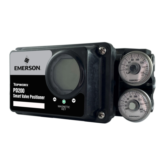
- Page 1 Installation, Operation, & Maintenance Manual ES-09374-1 August 23, 2022 Emerson TopWorx PD200 Smart Valve Positioner...
- Page 2 aphics PMS 151 WARNING C0 M55 Y100 K0 sented. Safe Use - User Instructions Installation, Operation, & Maintenance Manual Rotary Actuator Installation (Continued) Installation, Operation, and Maintenance Manual Mechanical Installation Rotary Actuator Installation (Continued) 3—January 15, 2021 August 23, 2022 ES-09374-1 ES-09373-1 June 14, 2022...
-
Page 3: Table Of Contents
Table of Contents Installation, Operation, & Maintenance Manual August 23, 2022 ES-09374-1 Contents Section 1: Introduction............5 General Notes................... 5 Proper Use....................5 Qualified Technical Staff................6 Exclusion of Liability.................. 6 Section 2: Specifications.............7 Section 3: Overview............9 Enclosure....................10 Identification Label Information............... 10 Scope of Supply.................. - Page 4 Table of Contents Installation, Operation, & Maintenance Manual August 23, 2022 ES-09374-1 Contents Section 8: Configuration...........45 Configuration Buttons................45 8.1.1 Magnetic Key................46 Entering and Navigating the Configuration Menu........47 Fast Calibration..................49 Fast PID....................50 Configuration Menu.................52 8.5.1 Display Menu................53 8.5.2 Setup Menu................56 8.5.3 Range Menu................58...
-
Page 5: Section 1: Introduction
This manual is not an integral part of the delivery of the positioner and is subject to change without notice. The manual is available for download on our website at www.emerson.com. For the sake of clarity, the manual does not contain all the detailed information on all versions of the product described, nor does it refer to all possible cases of installation, operation, maintenance and use in systems. -
Page 6: Qualified Technical Staff
All mounting and configuration of the positioner must be performed by qualified personnel strictly following the guidelines contained in this manual. Emerson TopWorx is not responsible for damages caused to persons or property resulting from incorrect installation and/or configuration. Introduction... -
Page 7: Section 2: Specifications
Specifications Installation, Operation, & Maintenance Manual August 23, 2022 ES-09374-1 SPECIFICATIONS Table 1 - Specifications Physical Specification Min. Typ. Max. 4-20mA input Signal 3.6 mA 4-20 mA DC, Nominal 25 mA (Overcurrent Protection) 12.2 VDC for analog Input Voltage 35 VDC control Overcurrent Protection Reverse Polarity... - Page 8 Specifications Installation, Operation, & Maintenance Manual August 23, 2022 ES-09374-1 Nominal signal range: 4 - 20 mA Power Supply: 10 – 30 Vdc External Load Resistance: 800 Ω @ 24 Vdc Output Position Position Error: Transmitter < 0.33% Temperature Error Effect: 0.01%/K °C Resolution: <...
-
Page 9: Section 3: Overview
Overview Installation, Operation, & Maintenance Manual August 23, 2022 ES-09374-1 OVERVIEW See below for parts of the PD200 positioner. To access the mechanical configuration buttons and electrical terminals, you must remove the product cover. To use the magnetic activation, it is not necessary to remove the cover. Figure 3-1 Overview Table 2 - Part Description Item... -
Page 10: Enclosure
Overview Installation, Operation, & Maintenance Manual August 23, 2022 ES-09374-1 Enclosure Enclosure manufactured with conductive type resin. This allows the housing to be grounded to avoid the accumulation of electrostatic charges that in classified areas can cause the ignition of the explosive atmosphere. Figure 3-2 Enclosure Identification Label Information These labels have information about the positioner such as coding, serial number,... - Page 11 Overview Installation, Operation, & Maintenance Manual August 23, 2022 ES-09374-1 Figure 3-4 Side Label Figure 3-5 Internal Label Front Label This label contains the following information: Manufacturer ID Order code Side Label This label carries the following information: Model number Serial Number Operation and certification Information Internal Tag...
-
Page 12: Scope Of Supply
Principle of Operation Installation, Operation, & Maintenance Manual August 23, 2022 ES-09374-1 Scope of Supply Check the packaging immediately after receiving the product. Make sure that the contents are undamaged and that they are in accordance with the scope of delivery and as described on the invoice. - Page 13 Principle of Operation Installation, Operation, & Maintenance Manual August 23, 2022 ES-09374-1 Figure 4-1 Operating Principle Principle of Operation...
-
Page 14: Section 5: Mechanical Installation
Mechanical Installation Installation, Operation, & Maintenance Manual August 23, 2022 ES-09374-1 MECHANICAL INSTALLATION The installation of the positioner will depend on the actuator type (linear or rotary). The following shows the types of pneumatic actuators and a brief overview of their operation. -
Page 15: Rotary Actuator Installation
1 - Mount the rotary adapter and tighten the screw with an 8 mm hex wrench. Figure 5-6 Rotary Adaptor 3—January 15, 2021 Mechanical Installation Installation, Operation, & Maintenance Manual nuals Installation, Operation, and Maintenance Manual Mechanical Installation August 23, 2022 ES-09374-1 ES-09373-1 June 14, 2022... - Page 16 Mechanical Installation Installation, Operation, & Maintenance Manual August 23, 2022 ES-09374-1 Figure 5-4 Mounting Kit for Rotary Actuator Mechanical Installation...
-
Page 17: Mounting The Rotary Namur Bracket To The Actuator
1 - Mount the rotary adapter and tighten the screw with an 8 mm hex wrench. Figure 5-6 Rotary Adaptor Mechanical Installation Installation, Operation, & Maintenance Manual August 23, 2022 ES-09374-1 5.3.1 Mounting the Rotary NAMUR Bracket to the Actuator 2 - The rotary support is factory assembled for actuators with 30x80 holes and 30mm Figure 5-5 Assembling the Bracket shaft height. - Page 18 Rotary Actuator Installation (Continued) Rotary Actuator Installation (Continued) Rotary Actuator Installation (Continued) 5.3.1 Mounting the Rotary NAMUR Bracket to the Actuator 5.3.1 Mounting the Rotary NAMUR Bracket to the Actuator 5.3.1 Mounting the Rotary NAMUR Bracket to the Actuator 1 - Mount the rotary adapter and tighten the screw with an 8 mm hex wrench. 1 - Mount the rotary adapter and tighten the screw with an 8 mm hex wrench.
- Page 19 Mechanical Installation Installation, Operation, & Maintenance Manual August 23, 2022 ES-09374-1 4 - Mount the positioner with bracket by engaging the positioner end cap on the shaft of the rotary actuator, attach the four M5x10 screws with lock washers and plain washers. Tighten the screws with an 8 mm wrench.
-
Page 20: Linear Actuator Installation
Mechanical Installation Installation, Operation, & Maintenance Manual August 23, 2022 ES-09374-1 Figure 5-11 Mounted Positioner Linear Actuator Installation See below the installation of the positioner on linear valves. Figure 5-12 Installation on a Linear Actuator Mechanical Installation... -
Page 21: Mounting The Guide Lever
aphics WARNING C0 M55 Y100 K0 sented. Mechanical Installation Installation, Operation, & Maintenance Manual PMS 109 August 23, 2022 ES-09374-1 CAUTION C3.1 M2 Y91.4 K.05 3—January 15, 2021 nuals ATTENTION PMS 186 DANGER C1.2 M92 Y92 K0 Before installing the positioner, check the area classification. Never use a General Purpose The positioner can be installed at any starting angle and operates in any position, positioner in an area classified as an explosive atmosphere. -
Page 22: Installation Of The Feedback Lever And Support
Rotary Support to the Actuator. Figure 5-7 Universal Rotary Mounting Kit Mechanical Installation Installation, Operation, & Maintenance Manual August 23, 2022 ES-09374-1 5.4.2 Installation of the Feedback Lever and Support Figure 5-14 Installing the Feedback Lever and Support 3 - Mount the bracket to the positioner by placing the four M6x10 screws with lock washers and plain washers. -
Page 23: Yoke Castle Mount
Mechanical Installation Installation, Operation, & Maintenance Manual August 23, 2022 ES-09374-1 5.4.3 Yoke Castle Mount Figure 5-15 Yoke-Type Bonnet Assembly 5.4.4 Mounting on a Pillar Type Castle Figure 5-16 Mounting on a Pillar-Type Castle 3—January 15, 2021 anuals aphics PMS 151 WARNING C0 M55 Y100 K0 sented. -
Page 24: Feedback Lever Types
Mechanical Installation Installation, Operation, & Maintenance Manual August 23, 2022 ES-09374-1 3 - Mount the bracket to the positioner by placing the four M6x10 screws with lock 5.4.5 Feedback Lever Types washers and plain washers. Tighten the screws with a 10 mm wrench. The feedback levers are classified by two stroke lengths (K3, and K4), which are directly Figure 5-8 Mounting the Bracket on the Positioner linked to the minimum and maximum operating stroke. - Page 25 Rotary Actuator Installation (Continued) ATTENTION 5.3.1 Mounting the Rotary NAMUR Bracket to the Actuator The positioner can be installed at any starting angle and operates in any position, 1 - Mount the rotary adapter and tighten the screw with an 8 mm hex wrench. Mechanical Installation Installation, Operation, &...
- Page 26 Mechanical Installation Installation, Operation, & Maintenance Manual August 23, 2022 ES-09374-1 3 - Mount the bracket to the positioner by placing the four M6x10 screws with lock Figure 5-20 Installing the Feedback Lever washers and plain washers. Tighten the screws with a 10 mm wrench. Figure 5-8 Mounting the Bracket on the Positioner ATTENTION The positioner can be installed at any starting angle and operates in any position,...
- Page 27 Mechanical Installation Installation, Operation, & Maintenance Manual August 23, 2022 ES-09374-1 4 - Install the guide pin in the feedback lever, observing the maximum travel of the valve. Tighten the retaining nut with a 10 mm hex wrench. Figure 5-22 Installing the Dowel Pin Figure 5-23 Guide Pin in the Correct Position (Valve Travel) 5 - Install the guide arm on the valve stem.
- Page 28 Mechanical Installation Installation, Operation, & Maintenance Manual August 23, 2022 ES-09374-1 Figure 5-24 Installing the Guide Arm on the Valve Stem 6 - Install the positioner with bracket onto the valve bonnet, using M8x16 screws. The guide pin should pass through the middle of the guide arm. Do not fully tighten the screws, to allow adjustment of the feedback lever.
- Page 29 Rotary Actuator Installation (Continued) Mechanical Installation Installation, Operation, & Maintenance Manual 5.3.1 Mounting the Rotary NAMUR Bracket to the Actuator Rotary Actuator Installation (Continued) August 23, 2022 ES-09374-1 1 - Mount the rotary adapter and tighten the screw with an 8 mm hex wrench. 5.3.1 Mounting the Rotary NAMUR Bracket to the Actuator Figure 5-6 Rotary Adaptor...
-
Page 30: Section 6: Pneumatic Connections
Figure 5-8 Mounting the Bracket on the Positioner Pneumatic Connections Installation, Operation, & Maintenance Manual August 23, 2022 ES-09374-1 PNEUMATIC CONNECTIONS 3—January 15, 2021 nuals Instrument air must be of better quality than industrial compressed air. Humidity, ATTENTION suspended particles, and oil can impair the instrument’s operation temporarily or permanently if internal parts wear out. -
Page 31: Manifold Types
Rotary Actuator Installation (Continued) ATTENTION 5.3.1 Mounting the Rotary NAMUR Bracket to the Actuator The positioner can be installed at any starting angle and operates in any position, 1 - Mount the rotary adapter and tighten the screw with an 8 mm hex wrench. Pneumatic Connections Installation, Operation, &... -
Page 32: Pneumatic Connection On Rotary Actuator
Pneumatic Connections Installation, Operation, & Maintenance Manual August 23, 2022 ES-09374-1 Pneumatic Connection on Rotary Actuator Check below the pneumatic connection for each type of rotary actuator. Figure 6-4 Pneumatic Connections on Rotary Actuators Pneumatic Connections... -
Page 33: Pneumatic Connection On Linear Actuator
Pneumatic Connections Installation, Operation, & Maintenance Manual August 23, 2022 ES-09374-1 2 - The rotary support is factory assembled for actuators with 30x80 holes and 30mm shaft height. If you need to modify these measures, refer to item 5.3.1 - Mounting the Rotary Support to the Actuator. -
Page 34: Section 7: Electrical Connections
Electrical Connections Installation, Operation, & Maintenance Manual August 23, 2022 ES-09374-1 ATTENTION The positioner can be installed at any starting angle and operates in any position, vertical or horizontal. ELECTRICAL CONNECTIONS CAUTION Be careful when handling compressed air hoses, make sure the line is disconnected Cable Entry before connecting it to the positioner. -
Page 35: Grounding
ATTENTION The positioner can be installed at any starting angle and operates in any position, Electrical Connections Installation, Operation, & Maintenance Manual vertical or horizontal. August 23, 2022 ES-09374-1 CAUTION Be careful when handling compressed air hoses, make sure the line is disconnected before connecting it to the positioner. - Page 36 Electrical Connections Installation, Operation, & Maintenance Manual August 23, 2022 ES-09374-1 Figure 7-3 Electrical Connection with Micro Switches and Feedback with active Input Card Electrical Connections...
- Page 37 Rotary Actuator Installation (Continued) 5.3.1 Mounting the Rotary NAMUR Bracket to the Actuator Electrical Connections Installation, Operation, & Maintenance Manual August 23, 2022 ES-09374-1 1 - Mount the rotary adapter and tighten the screw with an 8 mm hex wrench. Figure 5-6 Rotary Adaptor Figure 7-4 Electrical Connection for Split Range Operation 2 - The rotary support is factory assembled for actuators with 30x80 holes and 30mm...
-
Page 38: Alarm Limit Switch Connection
5.3.1 Mounting the Rotary NAMUR Bracket to the Actuator 1 - Mount the rotary adapter and tighten the screw with an 8 mm hex wrench. Figure 5-6 Rotary Adaptor Electrical Connections Installation, Operation, & Maintenance Manual August 23, 2022 ES-09374-1 Alarm Limit Switch Connection The positioner is supplied with two micro switches that are used as low and high alarm. - Page 39 Electrical Connections Installation, Operation, & Maintenance Manual August 23, 2022 ES-09374-1 1 - Remove the main cover by removing the four screws that hold it in the positioner body. Figure 7-6 Removing Screws 2 - Pull the cover with your hand to remove it from the positioner. Figure 7-7 Pull the Cover Off 3 - When removing the main cover, observe the two screws that hold the display and the configuration buttons.
- Page 40 Electrical Connections Installation, Operation, & Maintenance Manual August 23, 2022 ES-09374-1 4 – To remove the internal cover with display, remove the two screws that hold the internal cover. Figure 7-9 Removing Screws 5 - Pull the cover with display by hand to remove it from the positioner. Figure 7-10 Pulling off the Internal Cover 6 - When removing the internal cover, observe the cams and jumpers of the alarms.
- Page 41 Electrical Connections Installation, Operation, & Maintenance Manual August 23, 2022 ES-09374-1 Figure 7-12 Location of Micro Switches, Cams and Jumpers Check the type of contact that will be used and if necessary, change the position of the jumpers. It is possible to use both switches with NO or as NC or one NO and another NC. Figure 7-13 Position of the Jumpers After automatic calibration, insert a multimeter set to measure resistance at the terminals of micro switch 2 (terminals 8 and 9).
- Page 42 Electrical Connections Installation, Operation, & Maintenance Manual August 23, 2022 ES-09374-1 Figure 7-14 NO Jumper Figure 7-15 NC Jumper Electrical Connections...
- Page 43 Electrical Connections Installation, Operation, & Maintenance Manual August 23, 2022 ES-09374-1 1 - Pull up the cam-lock to remove it and have access to the cam adjustment. Figure 7-16 Removing the Lock 2 - Remove the upper cam to access the lower cam setting (switch 2). Figure 7-17 Removing the Top CAM 3 - Lift and rotate the lower cam slowly.
- Page 44 Electrical Connections Installation, Operation, & Maintenance Manual August 23, 2022 ES-09374-1 4 - After checking the switching point in the desired position, replace the lower cam. Figure 7-19 Lowering Lower Cam 5 - After adjusting the switch point 2, move the valve manually to the position where you want switch 1 to change its state.
-
Page 45: Section 8: Configuration
Configuration Installation, Operation, & Maintenance Manual August 23, 2022 ES-09374-1 CONFIGURATION Configuration Buttons The PD200 positioner has 3 mechanical buttons and 3 magnetic buttons for configuration. To configure the positioner by the mechanical buttons it is necessary to open the cover by removing the four screws that hold it to the positioner enclosure. For configuration using the magnetic buttons, it is not necessary to remove the cover. -
Page 46: Magnetic Key
Configuration Installation, Operation, & Maintenance Manual August 23, 2022 ES-09374-1 8.1.1 Magnetic Key A magnetic key is provided with the positioner to operate the buttons without opening the enclosure. This key has two sides, one black for the North pole (N) and the other side green for the South pole (S). -
Page 47: Entering And Navigating The Configuration Menu
Configuration Installation, Operation, & Maintenance Manual August 23, 2022 ES-09374-1 Entering and Navigating the Configuration Menu To enter and navigate in the configuration menu utilizing the magnetic buttons, it is not necessary to open the cover of the enclosure. To use the mechanical buttons, it is necessary to remove the cover. - Page 48 Configuration Installation, Operation, & Maintenance Manual August 23, 2022 ES-09374-1 Figure 8-7 Entering the Menu Configuration...
-
Page 49: Fast Calibration
Configuration Installation, Operation, & Maintenance Manual August 23, 2022 ES-09374-1 Fast Calibration When executing fast calibration, the positioner performs the complete calibration, obtaining all the parameters of the valve. For example, the open position, closed position and the PID values. At any time, it is possible to interrupt the calibration process. -
Page 50: Fast Pid
Configuration Installation, Operation, & Maintenance Manual August 23, 2022 ES-09374-1 Fast PID It is possible to access the PID parameters without having to enter and go through the configuration menu. To do this, execute the following procedure: 1 - Use the DOWN key for 5 seconds. 2 - The display will show “FULL”. - Page 51 Configuration Installation, Operation, & Maintenance Manual August 23, 2022 ES-09374-1 Configuration...
-
Page 52: Configuration Menu
Configuration Installation, Operation, & Maintenance Manual August 23, 2022 ES-09374-1 Configuration Menu The PD200 configuration menu has fifteen functions that can be configured by mechanical or magnetic buttons. When the Menu is accessed, the positioner goes from operation mode (RUN) to configuration mode. Figure 8-10 Configuration Menu Configuration... -
Page 53: Display Menu
Configuration Installation, Operation, & Maintenance Manual August 23, 2022 ES-09374-1 8.5.1 Display Menu Figure 8-11 Display Menu In this function it is possible to select 5 display modes on the LCD display. 1.1 - POS (Position): Indicates the current valve position from 0% to 100%. 1.2 - SP (Set Point): Indicates the current value of the positioner input signal from 0% to 100%. - Page 54 Configuration Installation, Operation, & Maintenance Manual August 23, 2022 ES-09374-1 Figure 8-12 Display Indication Options Figure 8-13 Menu Display Configuration...
- Page 55 Configuration Installation, Operation, & Maintenance Manual August 23, 2022 ES-09374-1 Accessing the Display Menu Press the ENTER key ○ for 3 seconds to access the menu. • Use the ENTER ○ key to select what the display will show. • •...
-
Page 56: Setup Menu
Configuration Installation, Operation, & Maintenance Manual August 23, 2022 ES-09374-1 3° Point: X = 16 mA Using the equation of the Figure 8-14, we have: 4° Point: X = 20 mA Using the equation of the Figure 8-14, we have: 8.5.2 Setup Menu In this function, it is possible to perform the 3 calibration modes of the positioner:... - Page 57 Installation, Operation, and Maintenance Manual Mechanical Installation Configuration Installation, Operation, & Maintenance Manual ES-09373-1 June 14, 2022 August 23, 2022 ES-09374-1 Figure 8-15 Menu Setup Rotary Actuator Installation (Continued) 5.3.1 Mounting the Rotary NAMUR Bracket to the Actuator 1 - Mount the rotary adapter and tighten the screw with an 8 mm hex wrench. Figure 5-6 Rotary Adaptor 2 - The rotary support is factory assembled for actuators with 30x80 holes and 30mm shaft height.
-
Page 58: Range Menu
Configuration Installation, Operation, & Maintenance Manual August 23, 2022 ES-09374-1 8.5.3 Range Menu Range, measuring range or working range is a set of values of the measured variable that are comprised between the minimum and maximum values of the measuring, transmission, or control capability of the instrument. - Page 59 Configuration Installation, Operation, & Maintenance Manual August 23, 2022 ES-09374-1 Figure 8-17 Range Menu Entering the Range Menu Press the ENTER key ○ for 3 seconds to access the menu. • • Use the DOWN key to go to the RANGE option. The UP key returns to the previous option.
-
Page 60: Menu Split Range
Configuration Installation, Operation, & Maintenance Manual August 23, 2022 ES-09374-1 8.5.4 Menu Split Range Split range control is a system in which there is only one control signal and more than one valve to be controlled. In the example below, it will assume that the output of the controller is sent to two valves. - Page 61 Configuration Installation, Operation, & Maintenance Manual August 23, 2022 ES-09374-1 Figure 8-19 PD200 in Split Range In this function, it is possible to adjust the positioner to operate from 4 to 12 mA or 12 to 20 mA. 4.1 - (4 ... 12mA): Split Range enabled from 4 to 12mA. 4.2 - (12 ...
- Page 62 Configuration Installation, Operation, & Maintenance Manual August 23, 2022 ES-09374-1 Figure 8-20 SPLT Menu Accessing the SPLT Menu Press ENTER ○ for 3 seconds to access the menu. • • Use the DOWN key to go to the SPLT option. The UP key returns to the previous option.
-
Page 63: Pid Menu
Configuration Installation, Operation, & Maintenance Manual August 23, 2022 ES-09374-1 8.5.5 PID Menu Proportional, integral and derivative control (PID control or simply PID) is a process control technique. It unites proportional, integral and derivative actions so that an error signal is minimized by the proportional action, zeroed by the integral action and obtained with an anticipative speed by the derivative action. - Page 64 Configuration Installation, Operation, & Maintenance Manual August 23, 2022 ES-09374-1 Figure 8-22 PI Control Chart Derivative Control The derivative action like the integral action works with time (Td) and is also used in conjunction with the proportional action (PD control). This control is very efficient with respect to correction because it starts the correction immediately as soon as the error starts (as the derivation of constant is always zero).
- Page 65 Configuration Installation, Operation, & Maintenance Manual August 23, 2022 ES-09374-1 PID Control • PID control uses proportional, integral, and derivative actions together. • As it joins all the control actions it makes the error correction faster and more assertive by eliminating the offset left by the proportional and derivative actions.
- Page 66 3 - Mount the bracket to the positioner by placing the four M6x10 screws with lock Configuration Installation, Operation, & Maintenance Manual washers and plain washers. Tighten the screws with a 10 mm wrench. August 23, 2022 ES-09374-1 Figure 5-8 Mounting the Bracket on the Positioner Ziegler and Nichols Method 3 - Mount the bracket to the positioner by placing the four M6x10 screws with lock Ziegler and Nichols suggested a process tuning rule to get a given performance...
- Page 67 Configuration Installation, Operation, & Maintenance Manual August 23, 2022 ES-09374-1 Figure 8-25 PID Menu Accessing the PID Menu Press ENTER ○ for 3 seconds to enter the menu. • • Use the DOWN key to move to the PID option. The UP-key returns to the previous option.
-
Page 68: Alarm Menu
3—January 15, 2021 Configuration Installation, Operation, & Maintenance Manual nuals August 23, 2022 ES-09374-1 ATTENTION The positioner can be installed at any starting angle and operates in any position, vertical or horizontal. aphics PMS 151 CAUTION WARNING C0 M55 Y100 K0 If you change any value, it will be implemented immediately, which can cause process Be careful when handling compressed air hoses, make sure the line is disconnected sented. - Page 69 Configuration Installation, Operation, & Maintenance Manual August 23, 2022 ES-09374-1 Figure 8-27 Alarm Menu 6.1 - E ALM: Enables the positioner alarm 6.1.1 - LOWER 6.1.2 - UPPER 6.2 - DESAB: Disables the alarm. Configuration...
-
Page 70: Action Menu
Configuration Installation, Operation, & Maintenance Manual August 23, 2022 ES-09374-1 8.5.7 Action Menu This function relates the control signal to the valve positioning: 7.1 - DIRECT: Direct Action: 4mA valve closed signal (0%). 20 mA signal, valve open (100%). 7.2 - REVERS: Reverse Action: 4mA signal, valve open (100%). 20 mA signal, valve closed (0%). -
Page 71: Mode Menu
Configuration Installation, Operation, & Maintenance Manual August 23, 2022 ES-09374-1 Accessing the Action Menu Press ENTER ○ for 3 seconds to enter the menu. • • Use the DOWN key to go to the ACTION option. The UP key returns to the previous option. -
Page 72: Func Menu
Configuration Installation, Operation, & Maintenance Manual August 23, 2022 ES-09374-1 Accessing the Mode Menu Press ENTER ○ for 3 seconds to enter the menu. • • Use the DOWN key to go to the MODE option. The UP key returns to the previous option. - Page 73 Configuration Installation, Operation, & Maintenance Manual August 23, 2022 ES-09374-1 Figure 8-31 Characteristic Curve Configuration...
- Page 74 Configuration Installation, Operation, & Maintenance Manual August 23, 2022 ES-09374-1 Figure 8-32 FUNC Menu Accessing the FUNC Menu Press ENTER ○ for 3 seconds to enter the menu. • • Use the DOWN key to go to the FUNC option. The UP key returns to the previous option.
-
Page 75: Trim Menu
Configuration Installation, Operation, & Maintenance Manual August 23, 2022 ES-09374-1 8.5.10 Trim Menu It allows correcting a small variation in the 4-20 mA signal. See the example below: 4: Set the input current as 0% closed valve. 20: Set the input current as 100% closed valve. Figure 8-33 TRIM Adjustment Example To make the adjustment, follow the procedure below: Figure 8-34 TRIM Menu... - Page 76 Configuration Installation, Operation, & Maintenance Manual August 23, 2022 ES-09374-1 Accessing the TRIM Menu Press ENTER ○ for 3 seconds to enter the menu. • • Use the DOWN key to go to the TRIM option. The UP key returns to the previous option.
-
Page 77: Lock Menu
Configuration Installation, Operation, & Maintenance Manual August 23, 2022 ES-09374-1 Figure 8-36 Feedback Signal Graph 8.5.11 Lock Menu In this menu function, the user has 2 operating modes: 11.2 - LOCK: Prevents the alteration of any positioner setting, preventing unauthorized persons from modify the operation. - Page 78 Configuration Installation, Operation, & Maintenance Manual August 23, 2022 ES-09374-1 Figure 8-37 LOCK Menu Accessing the LOCK Menu Press ENTER ○ for 3 seconds to enter the menu. • • Use the DOWN key to go to the LOCK option. The UP key returns to the previous option.
-
Page 79: Time Menu
Configuration Installation, Operation, & Maintenance Manual August 23, 2022 ES-09374-1 8.5.12 Time Menu This function is designed to store the maximum angle and times it takes for the valve to open and close completely for future diagnostic purposes. The opening and closing times and the maximum angle are stored each time a FULL or AUTO calibration is performed, and these values will remain stored until a new calibration updates the new conditions. - Page 80 Configuration Installation, Operation, & Maintenance Manual August 23, 2022 ES-09374-1 Figure 8-40 TIME Menu Accessing the TIME Menu Press ENTER ○ for 3 seconds to enter the menu. • • Use the DOWN key to go to the TIME option. The UP key returns to the previous option.
-
Page 81: T Out Menu
Configuration Installation, Operation, & Maintenance Manual August 23, 2022 ES-09374-1 8.5.13 T OUT MENU This option allows you to adjust the time the positioner uses to perform the calibration. The time of the positioner is programmed at the factory for 10 seconds but can be set from 10 to 120 seconds. - Page 82 3 - Mount the bracket to the positioner by placing the four M6x10 screws with lock washers and plain washers. Tighten the screws with a 10 mm wrench. Figure 5-8 Mounting the Bracket on the Positioner Configuration Installation, Operation, & Maintenance Manual August 23, 2022 ES-09374-1 Accessing the T OUT Menu...
-
Page 83: Air To Menu
Configuration Installation, Operation, & Maintenance Manual August 23, 2022 ES-09374-1 3 - Failure in the learning cycles of the open and closed points: Imagine the condition where Tout is set to 10 seconds and that the set (positioner/ actuator) was able to perform the 1st cycle of learning the open and closed points, but when starting the second or third cycle, a failure of lack of compressed air occurs. - Page 84 Configuration Installation, Operation, & Maintenance Manual August 23, 2022 ES-09374-1 Set to Air to OPEN: Figure 8-42 Air to Open Set to Air to CLOSE: Figure 8-43 Air to Close Configuration...
- Page 85 Configuration Installation, Operation, & Maintenance Manual August 23, 2022 ES-09374-1 Figure 8-44 AIR TO Menu Accessing the AIR TO Menu Press ENTER ○ for 3 seconds to enter the menu. • • Use the DOWN key to go to the AIR TO option. The UP key returns to the previous option.
-
Page 86: Reset Menu
Configuration Installation, Operation, & Maintenance Manual August 23, 2022 ES-09374-1 8.5.15 RESET Menu In this menu function, all default values can be restored. SURE: Returns the factory settings. QUIT: Returns to the main menu without resetting. Figure 8-45 RESET Menu Accessing the RESET Menu Press ENTER ○... - Page 87 Configuration Installation, Operation, & Maintenance Manual August 23, 2022 ES-09374-1 Factory Standard When performing the reset, the following parameters will be changed: Figure 8-46 Factory Defaults (Standards) Configuration...
-
Page 88: Section 9: Certifications
Certifications Installation, Operation, & Maintenance Manual August 23, 2022 ES-09374-1 CERTIFICATIONS (Pending) Intrinsically Safe Entity Parameters: • CN1 4-20ma Input: • Ui=28V, Ii=93mA, Pi=651mW, Ci=6.4nF, Li=0µH • CN7 4-20ma Position Indication: • Ui=28V, Ii=93mA, Pi=651mW, Ci=22nF, Li=0µH • Alarm Switches (Connectors CN4 and CN5): •... - Page 89 Certifications Installation, Operation, & Maintenance Manual August 23, 2022 ES-09374-1 • IEC 61000-4-5 - Surge Immunity Test - PD200: input 4 to 20mA:1 kV - Line to Ground. Feedback 4 to 20 mA, PNP1 and PNP2: 1kV Line to Line. PD100: input 4 to 20mA:1 kV - Line to Ground.
-
Page 90: Installation In Potentially Explosive Atmosphere
3—January 15, 2021 nuals Certifications Installation, Operation, & Maintenance Manual August 23, 2022 ES-09374-1 aphics Installation in Potentially Explosive PMS 151 WARNING C0 M55 Y100 K0 Atmosphere sented. The PD200 positioner is intended for installation in potentially explosive atmospheres PMS 109 and is designed to meet IEC / EN 60079-0, IEC / EN 60079-11 intrinsic safety standards. -
Page 91: Example Of Intrinsically Safe Connection
Certifications Installation, Operation, & Maintenance Manual August 23, 2022 ES-09374-1 9.1.2 Example of Intrinsically Safe Connection Figure 9-1 Example of Intrinsically Safe Connection Figure 9-2 Positioner with Micro Alarm Switch and Feedback Certifications... - Page 92 Rotary Actuator Installation (Continued) 5.3.1 Mounting the Rotary NAMUR Bracket to the Actuator 1 - Mount the rotary adapter and tighten the screw with an 8 mm hex wrench. Certifications Installation, Operation, & Maintenance Manual Figure 5-6 Rotary Adaptor August 23, 2022 ES-09374-1 Figure 9-3 Split Range Operating Positioner 2 - The rotary support is factory assembled for actuators with 30x80 holes and 30mm...
-
Page 93: Section 10: Mechanical Dimensions
Mechanical Dimensions Installation, Operation, & Maintenance Manual August 23, 2022 ES-09374-1 MECHANICAL DIMENSIONS 10.1 Rotary Positioner Dimensions Figure 10-1 Rotary Positioner with Pressure Gauge Mounting Torque: Positioner in the mounting bracket (4xM6): 10 Nm Mounting bracket on the rotary actuator (4XM5): 10 Nm Mechanical Dimensions... -
Page 94: Linear Positioner Dimensions
Mechanical Dimensions Installation, Operation, & Maintenance Manual August 23, 2022 ES-09374-1 10.2 Linear Positioner Dimensions Figure 10-2 Linear Positioner Mechanical Dimensions... -
Page 95: Section 11: How To Specify
How To Specify Installation, Operation, & Maintenance Manual August 23, 2022 ES-09374-1 HOW TO SPECIFY • PD200-HSNGXX0000-ES PD200 - H (4-20mA with HART) - S (Mechanical Key + 4-20mA Position Transmitter), - N (One input conduit 1/2” NPT / Manifold 1/4” NPT standard), – G (Long manifold with two PSI manometers) - XX (RN [Rotating NAMUR adapter], K3 [Linear with 5 to 120mm feedback lever), and K4(Linear with 80 to 200mm feedback lever]), - 00 (Future placeholder for mounting bracket Options), - 00 (Future placeholder for additional... - Page 96 © 2013-2022 TopWorx, All rights reserved. TopWorx™, and GO™ Switch are all trademarks of TopWorx™. The Emerson logo is a trademark and a service mark of Emerson Electric. Co. © 2013-2022 Emerson Electric Company. All other marks are the property of their respective owners.