Emerson TopWorx D Series Installation, Operation & Maintenance Manual
Hide thumbs
Also See for TopWorx D Series:
- Quick start manual (2 pages) ,
- Mounting instructions (3 pages)
Quick Links
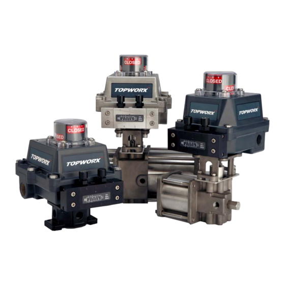
TopWorx
Installation, Operation & Maintenance Manual
Table of Contents
2
Switchbox Orientation
3
3
4
DXP Dimensional Drawing
3
DXP - IIC Dimensional Drawing
6
DXS Dimensional Drawing
7
DXR Dimensional Drawing
8
9
10
SCM Calibration
11
12
Spool Valves & Pilots
13
14
15
™
D-Series with AS-interface

Related Manuals for Emerson TopWorx D Series


Summary of Contents for Emerson TopWorx D Series
-
Page 1: Table Of Contents
™ TopWorx D-Series with AS-interface Installation, Operation & Maintenance Manual Table of Contents Switchbox Orientation Mounting Storage DXP Dimensional Drawing DXP - IIC Dimensional Drawing DXS Dimensional Drawing DXR Dimensional Drawing Shaft Detail Enclosure/Indicator Assembly SCM Calibration Spool Valves & Pilots Spool Valves &... - Page 2 D-Series with AS-I Installation, Operation & Maintenance 502.969.8000 Installation on Actuator Orientations, Normal and Reverse Acting Normal acting is full CW when the process valve is closed and CCW when the process valve is open. Reverse acting is full CW when the process valve is open and CCW when the process valve is closed. 90°...
-
Page 3: Mounting
www.topworx.com Installation on Actuator (continued) Mounting TopWorx™ has numerous mounting bracket kits available to meet your specific application, whether rotary or linear. Consult your local distributor or factory representative for ordering information. The illustration shows a direct Namur mount on a quarter turn valve. Refer to your mounting kit documentation for specific mounting instructions. Storage Until conduit, conduit plugs, and any applicable spool valve port connections are properly installed, the TopWorx™... - Page 4 D-Series with AS-I Installation, Operation & Maintenance 502.969.8000 Dimensions and Materials: TopWorx™ DXP MATERIALS OF CONSTRUCTION Illustration #4 Cast A360 aluminum with dichro- mate conversion coating inside & Enclosure MINIMUM 2.5" REQUIRED CLEARANCE out, epoxy coated exterior rated for IN ORDER TO DISINGAGE THE SHAFT FROM THE ID BUSHING 250 hrs salt spray per ASTM B117 AND REMOVE LID WHERE OPTIMUM CONDITIONS APPLY 304 Stainless Steel standard...
- Page 5 www.topworx.com Dimensions and Materials: TopWorx™ DXP - IIC Illustration #5 MATERIALS OF CONSTRUCTION Cast A360 aluminum with dichro- mate conversion coating inside & Enclosure out, epoxy coated exterior rated for 250 hrs salt spray per ASTM B117 304 Stainless Steel standard Fasteners 316 Stainless Steel optional 304 Stainless Steel standard...
- Page 6 D-Series with AS-I Installation, Operation & Maintenance 502.969.8000 Dimensions and Materials: TopWorx™ DXS Illustration #6 MATERIALS OF CONSTRUCTION MINIMUM 2.5" REQUIRED CLEARANCE IN ORDER TO DISINGAGE THE SHAFT FROM THE ID BUSHING Enclosure Cast 316 Stainless Steel AND REMOVE LID WHERE OPTIMUM CONDITIONS APPLY 304 Stainless Steel standard Fasteners 316 Stainless Steel optional...
- Page 7 www.topworx.com Dimensions and Materials: TopWorx™ DXR Illustration #7 MATERIALS OF CONSTRUCTION MINIMUM 2.5" REQUIRED CLEARANCE IN ORDER TO DISINGAGE THE SHAFT FROM THE ID BUSHING ® AND REMOVE LID WHERE OPTIMUM CONDITIONS APPLY Valox Enclosure Polybutylene Terephthalate (PBT) 304 Stainless Steel standard Fasteners 316 Stainless Steel optional 304 Stainless Steel standard...
-
Page 8: Shaft Detail
D-Series with AS-I Installation, Operation & Maintenance 502.969.8000 Dimensions and Materials: Shafts Illustration #8 Shaft Detail... -
Page 9: Enclosure/Indicator Assembly
www.topworx.com Illustration #9: Enclosure Assembly Indicator Assembly See Illustration #2 Screws are captive Shaft Assembly See Illustration #7 Sensor Pilot Device Options: Options: See Illustration Illustration pg. 10 Internal Ground O-ring Seal External Ground Lug Valve Options: See Illustration #4 Conduit Entry Illustration #10: Indicator Assembly Indicator Dome,... - Page 10 D-Series with AS-I Installation, Operation & Maintenance 502.969.8000 Illustration #11: SCM-ASI Illustration #12: SCM-ASI Sensor Communication Module Wiring Diagram Calibration Switch CLOSE ASI OPEN AS-i Close Terminals LEDs Open Solenoid AUX Input Terminals Terminals TopWorx SCM-ASi 2.1 Solenoid Note: Internal mount pilot in the DXP/DXS is 0.6W. For any externally mounted, or customer supplied, solenoid valve 4 watt maximum power consumption is allowed.
- Page 11 www.topworx.com Pneumatic Hookup Procedures Spool Valve Specifications Prior to connecting the supply air to the spool valve, flush the Medium Dried, filtered air (40 micron) system to remove any debris or contaminates. Galvanized Max Operating 100psi (0.7 MPa) (6.89Bar) pipe can easily flake and contaminate the system and there- Pressure fore is not recommended.
-
Page 12: Spool Valves & Pilots
D-Series with AS-I Installation, Operation & Maintenance 502.969.8000 Spool Valves and Pilots Illustration #13: Spool Valve Assembly Fail Closed Spool Valve Replacement Assemblies AV-BFCVA20 Std Alum Spool Valve Assy w/Buna seals AV-BFCVS20 Std 304SS Spool Valve Assy w/Buna seals AV-BFCV620 Std 316SS Spool Valve Assy w/Buna seals Flame arrestor O-ring (x5) -
Page 13: Safe Use
www.topworx.com Safe Use Special Conditions of Safe Use (All installations) Clean only with a damp cloth to prevent possibility of electrostatic discharge. For Explosion Proof installations, the internal ground connection shall be used and the external ground connection, if supplied in addition, is supplemental bonding allowed where local authorities permit, or is required. When installing with a third party listed nipple-mount solenoid, it is the responsibility of the installer to provide fittings, and apparatus, suitable for the area classification in accordance with the National Electrical Code. -
Page 14: Certifications & Approvals
D-Series with AS-I Installation, Operation & Maintenance 502.969.8000 Certifications & Approvals... -
Page 15: Warranty
www.topworx.com Warranty... - Page 16 The Emerson logo is a trademark and a service mark of Emerson Electric Co. ©2015 Emerson Electric Co. ©2015 TopWorx™, All rights reserved.TopWorx, Valvetop, and GO Switch are trademarks of TopWorx™. All other marks used in this document are the property of their respective owners.