GE Fuji Electric AF-300 Mini Startup Manual
Hide thumbs
Also See for Fuji Electric AF-300 Mini:
- Instructions manual (78 pages) ,
- Instructions manual (44 pages)
Table of Contents
Quick Links
Chapters
Table of Contents

Related Manuals for GE Fuji Electric AF-300 Mini


Summary of Contents for GE Fuji Electric AF-300 Mini
- Page 1 GEH-6647 AF-300 Mini ™ Startup Guide...
- Page 2 The information is supplied for informational purposes only, and GE Fuji makes no warranty as to the accuracy of the information included herein. Changes, modifications and/or improvements to equipment and specifications are made periodically and these changes may or may not be reflected herein.
-
Page 3: Table Of Contents
Contents Preface 4 Running the Motor Safety Precautions ..............ii 4.1 Motor Testing..............4-1 Conformity to UL standards and Canadian standards 4.1.1 Inspection and Preparation prior to (cUL certification) ..............v Operation..............4-1 Conformity to the Low Voltage Directive in the EU....v 4.1.2 Turning on Power and Checking ......4-1 Precautions for Use..............ix 4.1.3 Preparation Before Running the Motor... -
Page 4: Safety Precautions
Preface • Although the AF-300 Mini is manufactured under strict quality control, be sure to install appropriate Thank you for purchasing an AF-300 Mini series drive. safety devices for applications where drive failure This product is designed to control a 3-phase induction could result in serious accident or material loss. - Page 5 WARNING • If the Stall Prevention function has been selected, the drive may operate with acceleration/deceleration • The drive must be securely grounded. times or frequencies different from those selected. Otherwise, electric shock or fire could occur. The drive installation must be such that safety is •...
- Page 6 Maintenance and inspection and parts replacement WARNING • Turn the power off and wait for at least five minutes before starting inspection. (Also check that the LED monitor is unlit, and verify that the dc voltage across the P (+) and N (-) terminals is lower than 25 Vdc.) Otherwise, electric shock could occur.
-
Page 7: Conformity To The Low Voltage Directive In The Eu
Conformity to the Low Voltage Directive in the EU If installed according to the guidelines given below, drives marked with CE or TUV are considered as compliant with the Low Voltage Directive 73/23/EEC. CAUTION 1. The ground terminal G should always be connected to the ground. Do not use only a residual-current-oper- ated protective device (RCD)/earth leakage circuit breaker (ELCB)* as the sole method of electric shock protec- tion. - Page 8 Conformity to the Low Voltage Directive in the EU (continued) CAUTION 9. Use wires listed in EN60204 Appendix C Main power circuit input DCR [P1 [L1/R, L2/S & L3/T] [L1/L Rated current (A) of MCCB Drive and P (+)] and L2/N] Grounding [G] *2 Applicable or RCD/ELCB *1 Drive...
- Page 9 Conformity to UL standards and Canadian standards (cUL certification) continued If installed according to the guidelines given below, Drives marked with UL/cUL are considered as compliant with the UL and CSA (cUL certified) standards. CAUTION 1. Solid state motor overload protection (motor protection by electronic thermal overload relay) is provided in each model.
- Page 10 Conformity to UL standards and Canadian standards (cUL certification) continued CAUTION 6. Install a UL certified fuse or curciut breaker between the power supply and the drive, referring to the table below. Class J Fuse Circuit Breaker Required torque lb/in (N/m) Wire size AWG or kcmil (mm Current (A) Current (A)
-
Page 11: Precautions For Use
(If constant torque is required in the rise low-speed range, either use a GE drive motor or a motor equipped with a separate cooling fan.) Application with Use of a drive does not increase vibration of a standard motor, but when the motor is mounted... - Page 12 When using a motor with a drive, the motor can be protected using the electronic thermal control ability of the drive. In addition to the operation level, set the motor type (standard motor Environmental or drive motor). For high-speed motors or water-cooled motors, set a small value for the thermal conditions time constant and protect the motor in combination with the “cooling system OFF”...
-
Page 13: How This Manual Is Organized
How this manual is organized This manual consists of chapters 1 through 10. 1 Before Using the Drive This chapter describes acceptance inspection and precautions for transportation and storage of the drive. 2 Mounting and Wiring the Drive This chapter covers operating environment, precautions for installing the drive, and wiring instructions for the motor and drive. - Page 14 AF-300 Mini Model Numbering System Diagram Description (X/N)NN GE Product Code AF-300 Drive Family Imput Voltage 1 = 115V 2 = 230V 4 = 460V Input Phase 1 = 1-Phase 3 = 3-Phase Horsepower F50 = 1/2 hp 001 = 1 hp...
- Page 15 AF-300 Mini Weights and Dimensions IP 20 - Protected Enclosure Rated Overload Catalog Weight Enclosure Output Model Number H x W x D (in) Rating (150%) Number (lbs) Current (A) 115 Vac, 1-Phase, 50/60Hz Input IP20 6KXC111F12X9 * * D7201 4.72 x 3.15 x 3.94 IP20 6KXC111F25X9 * *...
- Page 16 AF-300 Mini Weights and Dimensions (continued) IP 20 - Protected Enclosure with Internal CE Filter Rated Overload Catalog Weight Enclosure Output Model Number H x W x D (in) Rating (150%) Number (lbs) Current (A) 230 Vac, 1-Phase, 50/60Hz Input IP20 6KXC121F12E9 * * D7301...
-
Page 17: Before Using The Drive
1 to 9: January to September X, Y, or Z: October, November, or December Production year: Last digit of year If you suspect the product is not working properly or if you have any questions about it, contact your dealer or GE Fuji. -
Page 18: External View And Terminal Blocks
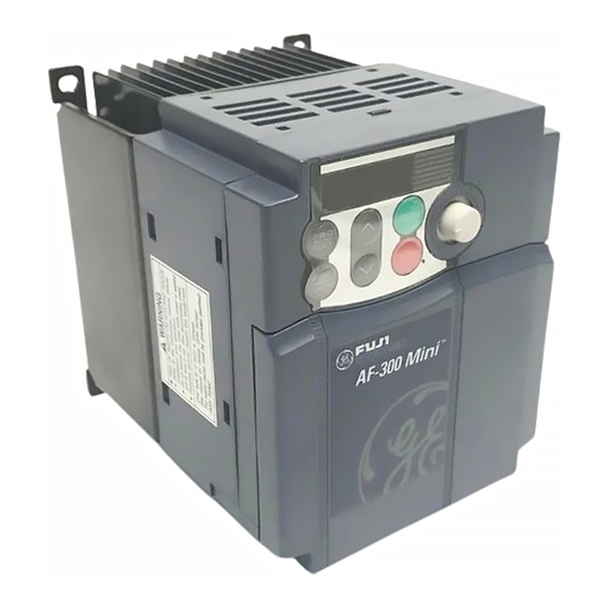
1.2 External View and Terminal Blocks External views Figure 1.2 External Views of the AF-300 Mini View of terminals (a) 230V 3-Ph 1 hp (b) 230V 3-Ph 2 hp (*When connecting the RS485 (option card) communications cable, remove the control circuit terminal block cover and cut off the barrier provided in it using nippers.) Figure 1.3 Bottom View of AF-300 Mini 1.3 Transportation... -
Page 19: Storage Environment
1.4 Storage Environment 1.4.1 Temporary storage Store the drive in an environment that satisfies the requirements listed in Table 1.1. Table 1.1 Environmental Requirements for Storage and Transportation Requirements Item Storage temperature (*1) -25 to +65 C (-4 to +149 °... - Page 20 Notes...
-
Page 21: Mounting And Wiring The Drive
2. Mounting and Wiring the Drive 2.1 Operating Environment Install the drive in an environment that meets the requirements listed in Table 2.1. Table 2.2 Output Attenuation Ratio with Altitude Table 2.1 Environmental Requirements Output current Item Specifications Altitude derate factor Site location Indoors 3300 ft (1000m) or lower... -
Page 22: Wiring
When mounting two or more drives Horizontal layout is recommended when two or more drives are to be installed in the same enclosure or power control board. As long as the ambient temperature is 40°C (104˚F) or lower, drives may be mounted side-by-side without any clearance between them. -
Page 23: Terminal Arrangement And Screw Specifications2-3
2.3.2 Terminal Arrangement and Screw Specifications The figures below show various arrangements of the main and control circuit terminals. This differs according to drive type. The two ground terminals provided, indicated by the symbol in Figures A to D, may be used inter- changeably for either the power supply side (primary circuit) or the motor side (secondary circuit). -
Page 24: Wiring Precautions
(2) Arrangement of the control circuit terminals (common to all AF-300 Mini models) Y1 Y1E FMA C1 PLC X1 CM FWD REV CM 30A 30B 30C Screw size: M 2 Tightening Torque: 1.8 lb-inch Screw size: M 2.5 Tightening Torque: 3.5 lb-inch Strip length of Dimension of openings in the control Terminal... -
Page 25: Wiring For Main Circuit Terminals And Ground Terminals
2.3.4 Wiring for Main Circuit Terminals and Ground Terminals Follow the procedure below. Figure 2.3 illustrates the wiring for peripheral equipment. Wiring Procedure (1) Ground terminals G (2) Drive output terminals (U, V, and W) (3) DC reactor connection terminals (P1 and P(+))* (4) Braking resistor connection terminals (P(+) and DB)* (5) DC link circuit terminals (P(+) and N(-))* (6) Main circuit power input terminals (L1/R, L2/S and L3/T) or (L1/L and L2/N) - Page 26 (2) Drive output terminals, U, V, and W The wiring procedure for the 6KXC_________ is shown below as an example. For other drive types, 1) Connect the three wires of the 3-phase motor to perform wiring in accordance with their individual terminals U, V, and W, aligning phases each other.
- Page 27 Consider any of the following measures: When a dc reactor is not to be connected together with the braking resistor 1) Use a motor with 1300V insulation. 1) Remove the screws from terminals P1 and P(+), 2) Connect an output circuit filter (option) to the output together with the jumper bar.
-
Page 28: Replacing The Main Circuit Terminal Block (Tb) Cover
NOTE: When replacin the main circuit TB cover, take other drives. care not to apply any stress to the wires. Stress on the NOTE: Consult GE Fuji if these terminals are to be used. wires imposes a mechanical force on the main circuit terminal screws, loosening them. -
Page 29: Wiring For Control Circuit Terminals
2.3.6 Wiring for Control Circuit Terminals Warning The outer jacket of control circuit cable is generally not insulated for high voltage levels. Therefore if the control circuit cabling comes into direct contact with the live main circuit terminal, the insulation may be insufficient. Accordingly, there is a possibility that DANGEROUSLY high voltage from the main power circuit could be applied to the control circuit wires. - Page 30 Table 2.4 Symbols, Names and Functions of the Control Circuit Terminals Classifi- Functions Symbol Name cation [13] Potentiometer Power supply (+10 Vdc) for frequency command potentiometer (Potentiometer: 1 to power supply 5 kΩ) Allowable output current: 10 mA [12] Voltage input The frequency is set according to the external analog input voltage.
- Page 31 Table 2.4 Continued Classifi- Symbol Name Functions cation [X1] Digital input 1 The various signals such as coast-to-stop, alarm from external equipment, and mul- tistep frequency selection can be assigned to terminals [X1] to [X3], [FWD] and [REV] by setting function codes E01 to E03, E98, and E99. For details, refer to Chapter 5, Section 5.2 “Overview of Function Codes.”...
- Page 32 Symbol Name Functions [FMA] Analog monitor The monitor signal for analog dc voltage (0 to +10 Vdc) is output. The signal functions can be selected from the following with function code F31. - Output frequency (before slip compensation) - Output frequency (after slip compensation) - Output current - Output voltage - Power consumption...
-
Page 33: Switching Of Sink/Source (Jumper Bar)
2.3.7 Switching of SINK/SOURCE (Jumper Bar) NOTE: Take care not to pinch the signal lines between the TB cover and drive body. Warning Before changing the jumper bar, wait for at least five minutes after the power has been turned off, then check with a multimeter that the dc voltage between main circuit terminals P (+) and N (-) does not exceed a safe voltage (25 V). - Page 34 – Mount the drive onto the metal board and – Connect a surge absorber in parallel with the connect the whole board to ground. coil or solenoid of the magnetic contactor. – Connect a noise filter to the drive power wires. (3) Leakage current 3) When implementing measures against noise gener- Harmonic component current generated by transistors...
-
Page 35: Recommended Wire Sizes
2.3.11 Recommended Wire Sizes Table 2.5 lists the recommended wire sizes. The wire size for the main circuit denotes the values for 75˚ C Cu wires at an ambient temperature of 50°C. Table 2.6 Recommended Wire Size Symbol Name Recommended wire size (AWG) *1 Main circuit Main power circuit input Applicable... - Page 36 Notes 2-16...
-
Page 37: Operation Using The Keypad
3. Operation Using the Keypad 3.1 Keys, Potentiometer, and LED on the Keypad As shown in the figure at below, the keypad consists of an LED monitor, a potentiometer (POT), and six keys. The keypad allows you to run and stop the motor, monitor running status, and switch to the menu mode. In the menu mode, you may set the function code data to match your operating requirements and monitor I/O signal states, maintenance information, and alarm information. -
Page 38: Overview Of Operation Modes
Simultaneous keying Simultaneous keying means depressing two keys at the same time (expressed by “+”). The AF-300 Mini supports simultaneous keying as listed below. (For example, the expression “ + keys” stands for pressing the key while holding the key down.) Operation modes Simultaneous keying Used to:... -
Page 39: Program Mode
3.2.2 Program Mode Program mode provides various functions, such as setting and checking function code data, monitoring mainte- nance information and checking input/output (I/O) signal status. These functions can be easily selected with the menu-driven system. Table 3.2 lists menus available in Program mode. The leftmost digit (numeral) of each letter string indicates the corresponding menu number and the remaining three digits indicate the menu contents. -
Page 40: Alarm Mode
3.2.3 Alarm Mode When the protection facility is activated to trigger an alarm, the drive automatically enters Alarm mode and the cor- responding alarm code will appear in the LED display. Figure 3.2 shows the status transition of Alarm mode. Releasing the Alarm and Transferring the Drive to Run Mode Remove the cause of the alarm and press the key to release the alarm and return to running status. -
Page 41: Operation In Run Mode
3.3 Operation in Run Mode If the drive is turned on, it automatically enters Run mode in which you may operate the following: (1) Run/Stop the Motor By factory default, pressing the key starts running the motor in the forward direction and pressing the decelerates the motor to stop. - Page 42 Make setting under PID control To enable PID control, you need to set function control code J01 data to 1 or 2. Under the PID control, the items that can be set or checked with the / keys are different from those under regular frequency control, depending upon the current LED monitor setting.
- Page 43 If you press the key in any conditions other than those described above, the following will appear: Frequency command Multistep Frequency PID control from communications frequency Displayed using command 1 (F01) cancelled link command PID enabled Disabled Disabled Frequency command by keypad Cancelled PID enabled PID output (as final frequency command)
- Page 44 Figure 3.3 Monitor Item Selection Example *1 The speed monitor can display the output frequency (Hz), set frequency (Hz), load shaft speed (rpm), line speed (m/min.), and constant feeding rate time (min.) which can be selected by with function code E48. *2 This PID-related information will appear only when the drive is under the PID control.
-
Page 45: Setting The Function Codes - "Data Setting
(4) Jog (Inch) the Motor In Run mode, pressing the + keys at the same time (simultaneous keying) can make the drive ready for jogging. The JoG appears on the LED monitor. To return the drive from the ready-to-jog state to the usual running state, press the keys simultaneously. - Page 46 Changing, reflecting, and saving of function code data during running Some function code data can be changed while the motor is running and some can not. Further, amongst the function codes whose data can be changed while the motor is running, there are some for which the changes can be reflected immediately and others for which that is not possible.
-
Page 47: Checking Changed Function Codes - "Data Checking"3-11
(3) Select the desired function code using the keys and press the key. (In this example, select function code F01.) The data for this function code will appear. (In this example, data 4 of F01 will appear.) (4) Change the function code data using the keys. - Page 48 3.6 Monitoring the Running Status – ”Drive monitoring” Menu #3 “drive monitoring” is used to check the running status during maintenance and test running. The display items for “drive monitoring” are listed in Table 3.5. Using keys, you may check those items in succession. Figure 3.7 shows the status transition diagram for “drive monitoring.”...
- Page 49 Displaying running status To display the running status in hexadecimal format, each state has been assigned to bit 0 to 15 as listed in Table 3.6. Table 3.7 shows the relationship between each of the status assignments and the LED monitor display. Table 3.8 gives the conversion table from 4-bit binary to hexadecimal.
-
Page 50: Checking I/O Signal Status - "I/O Checking
Hexadecimal expression A 16-bit binary number is expressed in hexadecimal format (4 digits). Table 3.8 shows the expression. The hexadeci- mals are shown as they appear on the LED monitor. Table 3.9 Binary and Hexadecimal conversion Binary Hexadecimal Binary Hexadecimal 3.7 Checking I/O Signal Status –... - Page 51 Table 3.10 I/O Check Items LED monitor Display contents Description display 4_00 I/O signals on the control circuit Shows the ON/OFF state of the digital I/O terminals. Refer to “Displaying control terminals I/O signal terminals” below for details on the display contents. I/O signals on the control circuit Shows the ON/OFF state for the digital input terminals that received a command 4_01...
-
Page 52: Reading Maintenance Information--"Maintenance Information
and [30C] are assigned to bit 8. The value “1” is set when the circuit between output terminals [30A] and [30C] is closed and the value “0” when the circuit between [30B] and [30C] is closed. For example, if [Y1] is ON and the cir- cuit between [30A] and [30C] are short-circuited with each other, then the display for LED4 to LED1 would be 0101. - Page 53 Table 3.12 Maintenance Display Items Monitor Display contents Description Display 5_00 Accumulated running time Shows the accumulated power-on time of the drive. Unit: thousands of hours. When the total ontime is less than 10,000 hours (display: 0.001 to 9.999), it is possible to check data in hourly units. When the total time is 10,000 hours or more (display: 10.00 to 65.53), the display will change to units of 10 hours.
-
Page 54: Reading Alarm Information - "Alarm Information
3.9 Reading Alarm Information – “Alarm information” Menu #6 [Alarm information] in Program mode shows the cause of the past 4 alarms as alarm codes. Further, it is also possible to display alarm information that indicates the status of the drive when the alarm occurred. Table 3.13 shows the contents of the alarm information and Figure 3.10 shows the status transition of the alarm information. - Page 55 Table 3.13 Alarm Information Contents LED monitor display Display contents Description (item No.) 6_00 Output frequency Output frequency before slip compensation 6_01 Output current Current output current 6_02 Output voltage Current output voltage 6_04 Set frequency Current set frequencies This shows the running direction being output. 6_05 Run direction F: normal;...
- Page 56 Notes 3-20...
-
Page 57: Running The Motor
4. Running the Motor 4.1 Running the motor for a test 4.1.1 Inspection and Preparation Prior to Operation Check the following prior to starting operation. (1) Verify correct connection. Carefully verify that the motor power cables are connected to drive output terminals U, V and W and that the ground cable is connected to the ground electrode correctly. -
Page 58: Test Run
REFERENCE: For details about how to set function code data, refer to Chapter 3, Section 3.4 “Setting the Function Codes.” Table 4.1 Settings of Function Code Data before Driving the Motor for a Test Function Name Function code data Factory setting code Base frequency 60.0 (Hz) -
Page 59: Function Codes
5. Function Codes 5.1 Function Code Tables Using negative logic for programmable I/O terminals Function codes enable the AF-300 Mini series of drives to be set up to match your system requirements. The negative logic signaling system can be used for the digital input and output terminals by setting the func- Each function code consists of a 3-character string. - Page 60 1_Active (motor with self-cooled fan, standard motor) overload relay 2_Active (motor with forced-cooled fan) (for motor protection) 0.00(Inactive),Approx. 1 to 135% of drive rated current 0.01 GE Motor (Level) rated 0.5 to 75.0min (Thermal time constant) Restart mode after (Select) 0_Inactive (Trip and alarm when power failure occurs.)
- Page 61 FMA Terminal (Function) Selects from the following items by code. 0_Output frequency (Before slip compensation) 1_Output frequency (After slip compensation) 2_Output current 3_Output voltage 6_Input power 7_PID feedback value 9_DC link circuit voltage 14_Analog output test (+) 0_Variable torque load Load select/Auto torque 1_Constant torque load boost/Energy-saving operation...
- Page 62 41_(1041)Low level current detection _IDL_ 99_(1099)Alarm fault (for any fault)_ALM_ Freq. detection 1 (FDT1) (Level) 0.0 to 400.0 Hz 60.0 OL early warnging/Current 0.00(Inactive),1 to 200% of drive rated current 0.01 GE Motor (Level 1) rated detection/Low level current 0.01 10.00 0.01 to 600.00s...
- Page 63 FWD terminal function (Select) Select from the following items by code. REV terminal function 0_(1000)Multistep freq. selection (0 to 7 stage) [SS1] 1_(1001)Multistep freq. selection (0 to 7 stage) [SS2] 2_(1002)Multistep freq. selection (0 to 7 stage) [SS4] 4_(1004)ACC/DEC time selection (2 stages) [RT1] 6_(1006)3-wire operation stop command [HLD]...
- Page 64 (Capacity) 0.01 to 10.00kW (when P99 =0.3.4) 0.01 Applied 0.01 Motor 0.01 to 10.00 HP (when P99=1) 0.01 GE Motor (Rated current) 0.00 to 99.99A rated (Slip compensation gain) 0.0 to 200.0% Motor select 0_Motor Specification0 (FUJI 8 Series) 1_Motor Specification1 (HP Motor)
- Page 65 See Note2. Current oscillation suppression 0.00 to 0.20 0.01 0.20 gain See Note2. STOP key priority / Start check Data function STOP key priority function OFF ON OFF ON Start check function OFF OFF ON Clear alram data Returns to zero after data clear by H97 setting at 1. Protection/ (Select) Data...
- Page 66 y codes: LINK Functions RS485 setting (Station address) 1 to 255 (Mode select on no 0_Trip and alarm (Er8) response error) 1_Operation for y03 timer, alarm (Er8) 2_Operation for y03 timer, and retry to communicate. If retry fails, the drive trips (Er8). 3_Continuous operation (Timer) 0.0 to 60.0s (Baud rate) 0_2400bps...
-
Page 67: Overview Of Function Codes
5.2 Overview of Function Codes When F02 = 0, to specify the motor rotational direc- tion by control signal input, assign the commands This section provides an overview of the function codes (FWD) and (REV) to terminals [FWD] and [REV], frequently used for the AF-300 Mini series of drives. - Page 68 Manual torque boost Maximum Frequency This feature manually adjusts the starting output voltage Sets the maximum frequency to drive the motor. Setting by setting F09 to an optimal torque boost rate to match the frequency out of the rated range for the equipment the motor and its load.
- Page 69 150% of the operating current speci- motor speed, the drive accelerates up to the previous fied by F11 flows continuously. The time constant of GE output frequency. Refer to the figure (F14 = 4) on the following page for details.
- Page 70 However to synchronize output frequency and motor F15, Frequency Limiter (Peak and Minimum) speed, the momentary overcurrent limiter (H12 = 1) should be enabled. Frequency limiter F15 limits the peak or maximum This setting is optimal for cases in which due to the output frequency.
- Page 71 Check braking resistor performance again and the same as that of GE Fuji’s conventional drive models. review the data setting of function codes F50 and F51. F20 to...
- Page 72 To assign negative logic input to any input terminal, set • Coast-to-stop command – (BX) the function code to the value of 1000s shown in ( ) in (Function code data = 7) Section 5.1 “ Function Code Tables.” To keep explana- Shorting the circuit between the (BX)-assigned terminal tions as simple as possible, the examples shown below and terminal [CM] will immediately shut down the drive...
- Page 73 When terminal command operation is selected (F02 = 1), control is normal, turning it ON switches it to inverse, or simultaneous keying is disabled. vice versa. • Select frequency command 2 or 1 – (Hz2/Hz1) (Function code data = 11) Turning the digital input signal (Hz2/Hz1) ON/OFF may switch the frequency setting method between frequency command 1 (defined by function code F01) and fre-...
- Page 74 Terminals [30A], [30B], and [30C] are mechanical relay level) or hardware (H12 = 1: Current limit). The minimum contacts. In normal logic, if an alarm occurs, the relay ON-duration is 100 ms. will be excited so that [30A] and [30C] will be short- •...
- Page 75 REFERENCE: For details, refer to Chapter 7, Section E50 Coefficient for Speed Indication 7.2, Table 7.2 “ Replacement Parts Judgement with This function code sets a coefficient to be used for Menu #5 “Maintenance Information” as a Guide.” setting the constant feeding rate time, load shaft speed •...
- Page 76 H03 (Initialize data) to 2 to initialize the motor parameter. This action automati- cally updates the data of function code P03 and the constants used inside the drive. When using GE standard motors, select the data listed below according to model. 5-18...
- Page 77 • Retry latency time (H05) If instantaneous overcurrent limiting is enabled, the drive will immediately turn off its output gates to suppress the Sets the latency time for automatic exit from Alarm increase of current and control the output frequency. mode.
- Page 78 Protection/Maintenance (Selection) Specify a combination between the output phase loss protection, input phase loss protection, and automatic carrier frequency lowering. Automatic lowering of carrier frequency When using a drive in a critical system or any other system where drive operation should not be interrupted, select this feature to protect the system from any failure resulting from the drive tripping due to the heat sink overheating (0H1) or overload (0LU), abnormally high...
-
Page 79: Troubleshooting
6. Troubleshooting 6.1 Before Proceeding with Troubleshooting WARNING If any of the protective functions have been activated, first eliminate the cause. Then, after checking that the all run commands are set to OFF, reset the alarm. Note that if the alarm is reset while any run commands are set to ON, the drive may supply power to the motor and cause it to start. -
Page 80: If No Alarm Code Appears On The Led Monitor
6.2 If no alarm code appears on the LED monitor 6.2.1 Motor is running abnormally [1] The motor does not rotate. What to Check and Suggested Measures Possible Causes No power supplied to the CHECK drive. Check nput voltage, output voltage and interphase imbalance. SUGGESTED ACTIONS –... - Page 81 Possible Causes What to Check and Suggested Measures The coast-to-stop com- CHECK mand was enabled Check the data of function codes E01, E02, E03, E98 and E99 using Menu #2 “Data checking” and the input signal status with Menu #4 “I/O checking.” SUGGESTED ACTIONS –...
- Page 82 Possible Causes What to Check and Suggested Measures The current limiting op- CHECK eration did not increase Check whether the current limiting is active or not using Menu #3 “drive monitoring” and the data for the the output frequency. current limiting level (F44). SUGGESTED ACTIONS –...
- Page 83 Possible Causes What to Check and Suggested Measures The system vibrates CHECK due to a too-compliant Cancel the automatic control system (automatic torque boost, slip compensation, energy saving mechanical coupling operation, overload prevention control, current limiting) and check that the motor vibration is suppressed between the motor and (F37, P09, H70, and F43).
-
Page 84: Problems With Drive Settings
[7] Power is restored after an instantaneous power failure, but the motor does not restart. Possible Causes What to Check and Suggested Measures The setting of function CHECK code F14 did not make Check if an undervoltage trip occurs. the motor restart even SUGGESTED ACTIONS if the power recovered –... -
Page 85: If An Alarm Code Appears On The Led Monitor
[3] Nothing appears on the LED monitor. Possible Causes What to Check and Suggested Measures No power supplied to the CHECK drive. Check input voltage, output voltage and interphase unbalance. SUGGESTED ACTIONS – Connect a molded case circuit breaker, an ground fault circuit interruptor (with the exception of those designed for protection from ground faults only) or a magnetic contactor. -
Page 86: Ou2 Overvoltage Protection
Possible Causes What to Check and Suggested Measures Acceleration/ decelera- CHECK tion time was too short. Check that the motor generates enough torque during acceleration/deceleration. The torque requirement is calculated from the moment of inertia of the load and the acceleration/deceleration time. SUGGESTED ACTIONS –... -
Page 87: Lu Undervolatge Protection
[3] LU Undervoltage protection Problem Intermediate dc circuit voltage was below the undervolatge detection level. Possible Causes What to Check and Suggested Measures An instantaneous power SUGGESTED ACTIONS failure occurred. – Reset the alarm. – To restart running the motor without an alarm, set F14 to a value of 4 or 5 depending on load. The power to the drive CHECK was switched back on... -
Page 88: Opl Output Phase Loss Protection
Possible Causes What to Check and Suggested Measures Cyclic overload occurred. CHECK Measure ripple wave of intermediate dc circuit voltage. SUGGESTED ACTIONS – If the ripple is large, raise the drive capacity 1-phase voltage was CHECK supplied to the drive Check the drive type. -
Page 89: Oh2 External Alarm Input
Possible Causes What to Check and Suggested Measures Excessive load. CHECK Measure the output current. SUGGESTED ACTIONS – Reduce the load (e.g. lighten the load before the overload protection occurs using the overload early warning (E34)). – Lower the carrier frequency (F26). –... - Page 90 Possible Causes What to Check and Suggested Measures The value set for the CHECK torque boost (F09) was Check the data of function code F09 and readjust the data so that the motor does not stall even if you set too high.
-
Page 91: Overload Protection
Possible Causes What to Check and Suggested Measures The characteristics of CHECK electronic thermal did not Check the motor characteristics. match those of the motor SUGGESTED ACTIONS overload. – Reconsider the data of function codes P99, F10 and F12. – Use an external thermal relay. Activation level for the CHECK electronic thermal relay... - Page 92 [12] Er1 Memory error Problem Error occurred in writing the data to the memory in the drive. Possible Causes What to Check and Suggested Measures Power supply turned off CHECK while drive was writing Check whether pressing the key resets the alarm after the function code data are initialized by setting data (especially initial- the data for function code H03 to 1.
- Page 93 [14] Er3 CPU error Problem A CPU error (e.g. erratic CPU operation) occurred. Possible Causes What to Check and Suggested Measures High intensity noise was CHECK applied to the drive. Check if appropriate noise control measures have been implemented (e.g. correct grounding and routing of control and main circuit wires).
- Page 94 Possible Causes What to Check and Suggested Measures Even though a response CHECK error detection time Check the high-level controllers. (y08) has not been set, SUGGESTED ACTIONS communications did not – Change the settings of high-level controller software, or make the no response error detection time occur cyclically.
-
Page 95: Maintenance And Inspection
7. Maintenance and Inspection To avoid failures and assure reliable long-term operation, make daily and periodic inspections. Take the following precautions while performing any maintenance work. WARNING The intermediate dc circuit capacitor may retain its charge for some time after power is turned off. Therefore it may take some time until the intermediate dc circuit voltage falls to a safe level. - Page 96 Table 7.1 List of Periodic Inspections Check part Check item How to inspect Evaluation criteria Structure such as Abnormal noise and excessive vibration Visual and audible inspec- 1), 2), 3), 4), 5) frame and cover Loose bolts tion No abnormalities Deformation and breakage Retighten.
- Page 97 Estimation of service life using maintenance information Menu #5 “Maintenance Information” in Program mode can be used to display the recommended time for replace- ment of the intermediate dc circuit capacitor, electrolytic capacitors on the printed circuit board, and cooling fan. When operating time exceeds the early warning level, an early warning signal is output to any external device through terminal [Y1] (function code E20).
-
Page 98: Measurement Of Electrical Values In Main Circuit
7.3 Measurement of Electrical Values in Main Circuit Because the voltage and current of the power supply (input) of the main circuit of the drive and the output (motor) include harmonic components, the indicated values vary according to the type of meter used to measure them. Use meters indicated in Table 7.3 when measuring for commercial frequencies. -
Page 99: Insulation Test
Each part of the product has its own service life that will vary according to the environmental and operating condi- tions. It is recommended that the following parts be replaced as specified below. When the replacement is necessary, contact your dealer where you purchased the product, or GE Fuji. Table 7.4 Replacement Parts... -
Page 100: Inquiries About Product And Warranty
If the drive is still under warranty, further information will be required per the “In- Warranty Failure Checklist” shown on page 7-7of this Start-up Guide. Out-of Warranty Procedures When the defective part has been identified, contact your local authorized GE standard drives distributor to order replacement parts. Motors Motor repairs on General Electric motors are generally handled by GE Authorized Electric Motor Servicenters or GE Apparatus Service Shops. - Page 101 After all of the Checklist information is acquired, contact the following number for assistance: (540) 387-5739 or (800) 533-5885 When returning failed parts, reference # on the shipping documents that came with the replacement parts and ship failed parts to GE Fuji Drives.
- Page 102 Notes...
-
Page 103: Specifications
*8) Voltage unbalance [%] = (Max voltage [V] - Min voltage [V]) / 3-phase average voltage [V] x 67 (IEC61800-3 (5.2.3)) If this value is 2 to 3%, use ac reactor (option). *9) Calculated under GE Fuji specified conditions. *10) Indicates product revision. - Page 104 *6) Average braking torque with AVR control OFF (varies with motor efficiency.) *7) Average braking torque using external braking resistor (optional) No braking resistor is available for 1/8 hp, 1/4 hp. *8) Calculated under GE Fuji specified conditions. *9) Indicates product revision.
- Page 105 *6) Average braking torque with AVR control OFF (varies with motor efficiency.) *7) Average braking torque using external braking resistor (optional) No braking resistor is available for 1/8 hp, 1/4 hp. *8) Calculated under GE Fuji specified conditions. *9) Indicates product revision.
- Page 106 *8) Voltage unbalance [%] = (Max voltage [V] - Min voltage [V]) / 3-phase average voltage [V] x 67 (IEC61800-3 (5.2.3)) If this value is 2 to 3%, use ac reactor (option). *9) Calculated under GE Fuji specified conditions. *10) Indicates product revision.
- Page 107 *6) Average braking torque with AVR control OFF (varies with motor efficiency.) *7) Average braking torque using external braking resistor (optional) No braking resistor is available for 1/8 hp, 1/4 hp. *8) Calculated under GE Fuji specified conditions. *9) Indicates product revision.
-
Page 108: Common Specifications
8.2 Common Specifications Item Explanation frequency 25 to 400 Hz Maximum Base frequency 25 to 400 Hz Starting frequency 0.1 to 60.0 Hz Carrier frequency 0.75 to 15k Hz (Frequency may drop automatically to protect the drive running at 7kHz or over.) Accuracy (Stability) Analog setting: ±2% of max freq. - Page 109 Item Explanation Frequency limiter High and low limiters [Hz] can be set. (Setting range: 0 to 400 Hz) Bias frequency Biases of set freq. and PID command can be set between 0 and ±100%. Gain for frequency Analog input gain can be set within the range from 0 to 200%. setting At voltage input, proportional frequency can be set to 10.5V and 21mA by adjusting gain.
- Page 110 Item Explanation Overcurrent Stops the drive by detecting overcurrent caused by overload in the output circuit. Short-circuit Stops the drive by detecting overcurrent caused by short-circuit in the output circuit. Ground fault Stops the drive by detecting overcurrent caused by ground fault in the output circuit. (Detected when the drive is started.) Overvoltage Stops the drive by detecting overvoltage (100V/200V series: 400 Vdc, 400V series: 800V) in dc link circuit.
-
Page 111: Terminal Specifications
8.3 Terminal Specifications 8.3.1 Terminal Functions For details about the main and control circuit terminals, refer to Chapter 2, Subsection 2.3.4 and Subsection 2.3.6 (Table 2.4), respectively. 8.3.2 Connection Diagram for Operation by External Signal Inputs Note 1: Install a recommended molded case circuit breaker or a ground fault circuit interrupter (GFCI) in the primary circuit of the drive to protect wiring. -
Page 112: External Dimensions
8.4 External Dimensions (See dimensions table on next page) 8-10... - Page 113 Dimensions inches (mm) Model No. 3-phase 230V ∗∗ 6KXC123F12X9 3.15 (80) 2.64 (67) 0.26 (6.5) 4.72 (120) 4.33 (110) 0.20 (5) 3.15 (80) 2.76 (70) 0.39 (10) 0.06 (1.5) 4-0.2 x 0.24 (4-5x6) ∗∗ 6KXC123F25X9 3.15 (80) 2.64 (67) 0.26 (6.5) 4.72 (120) 4.33 (110) 0.20 (5) 3.15 (80) 2.76 (70) 0.39 (10) 0.06 (1.5) 4-0.2 x 0.24 (4-5x6) ∗∗...
- Page 114 Dimensions inches (mm) Model No. 3-phase 230V 6KXC123002X9 * * 5.47 (139) 2.95 (75) 2.52 (64) 6KXC123003X9 * * 5.47 (139) 2.95 (75) 2.52 (64) 3-phase 460V 6KXC143F50X9 * * 4.53 (115) 2.95 (75) 1.57 (40) 6KXC143001X9 * * 5.47 (139) 2.95 (75) 2.52 (64) 6KXC143002X9 * *...
- Page 115 Dimensions inches (mm) Model No. 3-phase 230V 6KXC123005X9 5.47 (139) 2.95 (75) 2.52 (64) 3-phase 460V 5.47 (139) 2.95 (75) 2.52 (64) 6KXC143005X9 1-phase 230V 5.47 (139) 2.95 (75) 2.52 (64) 6KXC121003X9 EMC Filters Built-in Type 3-phase 230V 7.17 (182) 4.65 (118) 2.52...
-
Page 116: Protective Functions
8.5 Protective Functions Alarm Name Description monitor output displays [30A, B, C] Overcurrent – Stops the motor to protect the drive from an overcurrent During acceleration protection resulting from overload. During deceleration – Stops the motor to protect drive from an overcurrent due to a short-circuit in the output circuit. - Page 117 Alarm Name Description monitor output displays [30A, B, C] Overload Outputs a preliminary alarm at a preset level before the motor is stopped by the early electronic thermal function, for the purpose of protecting the motor. warning Stall prevention Operates when the current limit is active. –...
- Page 118 Notes 8-16...
-
Page 119: List Of Peripheral Equipment And Options
9. List of Peripheral Equipment and Options The table below lists the main peripheral equipment and options that may be connected to the AF-300 Mini. Use them in accordance with your system requirements. REFERENCE: For details, refer to the AF-300 Mini User’s Manual, Chapter 6 “Selecting Peripheral Equipment.” Name of peripheral Function and application... - Page 120 Name of peripheral Function and application equipment WARNING When connecting the drive to the power supply, add a recommended molded case circuit breaker in the power supply circuit. Do not use the devices with the rated current out of the recommenced range.
- Page 121 Name of option Function and application Braking resistors A braking resistor converts regenerative energy derived from deceleration of the motor and converts (Standard model) it to heat for dissipation. Use of a braking resistor results in improved deceleration performance of the (DBRs) drive.
- Page 122 Name of option Function and application Ferrite ring reactors for An ACL is used to reduce radio-frequency noise emitted by the drive. reducing radio frequency noise An ACL suppresses the outflow of high frequency harmonics caused by the switching (ACL) operation in the drive’s internal power supply lines.
-
Page 123: Compliance With Standards
For this reason, systems to be certified by UL and cUL GE Fuji’s CE mark is indicated under the condition that If you want to use the AF-300 Mini series of drives as a the product shall be used within equipment meeting all part of a UL Standards or CSA Standards (cUL certified) requirements for the relevant Directives. -
Page 124: Harmonics Component Regulation In The Eu
(2) Use shielded wires for the motor power cable and route it as short as possible. Firmly clamp the wire shield to the flange to ground it. Further, connect the wire shield electrically to the grounding terminal of motor. (See Figure 10.2.) (3) Use shielded wires for the control signals of the drive to input to/output from the control terminals. -
Page 125: Compliance With The Low Voltage Directive In The Eu
EU 10.5.1 General comments General-purpose drives are regulated by the Low Voltage Directive in the EU. GE Fuji has obtained the proper certification for the Low Voltage Directive from the official inspection agency. GE Fuji states that all our drives with CE and/or TÜV marking are compliant with... - Page 126 Notes 10-4...
- Page 127 GE Fuji Drives USA, Inc. 1501 Roanoke Blvd. Suite 435 Salem, VA 24153 www.GEindustrial.com GEH-6647 030205 INR-Si47-0817-E...