
Related Manuals for Honeywell TA3840


Summary of Contents for Honeywell TA3840
- Page 1 Data Processing Racks TA3840 Maintenance Manual SAS au Capital de 2 158 244 € - 444 871 933 R.C.S. Bourges - APE : 2651B Headquarter : 9, rue Isaac Newton - 18000 Bourges - France...
- Page 2 Data Processing Racks Maintenance Manual TA3840 Edition Released February 2013...
- Page 3 INTRODUCTION This manual is issued specifically for the data processing racks of the TA3840 or EMx40 system. It contains instructions detailed for functioning, operation and cleaning of this system. To use it in an optimal way, we advise you TO READ CAREFULLY THESE INSTRUCTIONS and to respect them throughout the life of the equipment.
- Page 4 The safety instructions given in this manual are merely given for guidance purposes to protect you and all those using and working on our equipments. Honeywell Marine cannot foresee all dangerous situations that might arise. This is why the owner and/or the operator is responsible for the operating safety of the system.
-
Page 5: Table Of Contents
TABLE OF CONTENTS 1. SYSTEM DESCRIPTION ....................... 6 Presentation ........................... 6 Electronic boards ..........................7 TA3840R - Remote display unit ...................... 8 2. SYSTEM MAINTENANCE ......................9 Maintenance help ........................... 9 Software updating ........................13 3. TROUBLESHOOTING GUIDE ..................... 15 4. -
Page 6: System Description
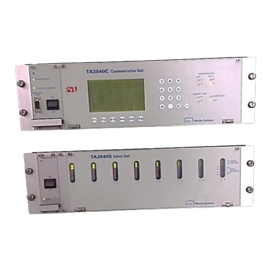
The racks TA3840C communication unit, TA3840R remote display unit, TA3840S safety unit are parts of the TA3840 system or EMx40 system, dedicated to monitor the tankers' liquid cargo parameters such as level, temperature and pressure, as well as all associated measurements, for the installed transmitters. -
Page 7: Electronic Boards
Remove the 2 upper screws of the front panel. Tilt the front panel while maintaining it to prevent that it goes out from its hinges - Risk of deterioration by falling. Doc No: MM5008E – Revision 6 – ENG Data Processing Racks TA3840 Maintenance Manual... -
Page 8: Ta3840R - Remote Display Unit
TA3840R - Remote display unit ● Remove from the back the 6 nuts fixing the front panel using a 7 mm spanner. Communication board LCD display board Doc No: MM5008E – Revision 6 – ENG Data Processing Racks TA3840 Maintenance Manual... -
Page 9: System Maintenance
Zero line modification for the displayed transmitter Acknowledgment of an alarm started during intervention in maintenance mode (1 push for each alarm) Return to the current page or maintenance menu Doc No: MM5008E – Revision 6 – ENG Data Processing Racks TA3840 Maintenance Manual... - Page 10 (changeable zero line the radar the radar parameter) (changeable parameter) TmpH TmpM TmpL mBAR 1220 Individual Temperatures Pressure Pressure zero code line (changeable parameter) Doc No: MM5008E – Revision 6 – ENG Data Processing Racks TA3840 Maintenance Manual...
- Page 11 Push ZLN for 1 and 2 groups. The following key-in line is displayed. ● Enter a value between the suggested Zero line ? mm[+-32767]=XXXXXX limits. Ã The new Distance zero line value is applied to the relevant transmitter. Doc No: MM5008E – Revision 6 – ENG Data Processing Racks TA3840 Maintenance Manual...
- Page 12 (refer to the table), description of the failure. The HISTORIC menu allows showing the list of the system faults since the oldest. Example of display Doc No: MM5008E – Revision 6 – ENG Data Processing Racks TA3840 Maintenance Manual...
-
Page 13: Software Updating
Monitoring 2 communication fault Software updating In case of updating, Honeywell Marine can provide a set of 2 EPROM'S per soft, one "EVEN" and one "ODD". The EPROM'S have to be inserted on relevant electronic boards at the same location than the old one's, taking care not to damage the pins of each EPROM. - Page 14 TA3840C CPU board EPROM even EPROM odd TA3840R communication board EPROM even EPROM odd Doc No: MM5008E – Revision 6 – ENG Data Processing Racks TA3840 Maintenance Manual...
-
Page 15: Troubleshooting Guide
When the cause of an incident is a blown out fuse, it is necessary to search the reason of the possible short circuit. Doc No: MM5008E – Revision 6 – ENG Data Processing Racks TA3840 Maintenance Manual... - Page 16 Rx. the radar. configuration of the radar. (*) refer to the relevant paragraph in "REMEDIAL MAINTENANCE" chapter. Doc No: MM5008E – Revision 6 – ENG Data Processing Racks TA3840 Maintenance Manual...
- Page 17 - Replace the CPU board (*). indicators flashing. Communication fault message for some radars. - No communication through - Refer to TA3840S rack TA3840S rack for some troubleshooting. channels. Doc No: MM5008E – Revision 6 – ENG Data Processing Racks TA3840 Maintenance Manual...
- Page 18 4-20 mA channels from one analog 4-20 mA relevant board. inputs board (*). inputs board (48 first channels or 48 further channels). (*) refer to the relevant paragraph in "REMEDIAL MAINTENANCE" chapter. Doc No: MM5008E – Revision 6 – ENG Data Processing Racks TA3840 Maintenance Manual...
-
Page 19: Remedial Maintenance
(*) refer to the relevant paragraph in "REMEDIAL MAINTENANCE" chapter. 4. REMEDIAL MAINTENANCE Recommended spare parts Two standard fuses kit are supplied by Honeywell Marine with the TA3840 system. ● Fuses kit for TA3840C and TA3840S class IIB: code 34766. - Page 20 When re-installing the CPU board, place the extractor levers in horizontal position, slide the board in its runners, push it until it is engaged, then lower the levers. ● Reconnect all connectors in the reverse order. Doc No: MM5008E – Revision 6 – ENG Data Processing Racks TA3840 Maintenance Manual...
- Page 21 Note: for a correct installation of the 2 ribbon cables on the CPU board, take care to respect the connectors location (refer to the figure below). To front panel (green ribbon cable) To LCD backlight To LCD display board (2-pins connectors) (two 10-pins connectors) Doc No: MM5008E – Revision 6 – ENG Data Processing Racks TA3840 Maintenance Manual...
- Page 22 TA3840S - Power supply board - Removing/installing/fuse replacement ● Unscrew the 4 screws, then pull the handle to extract the electronic board from the rack. F1 - 1 A temporised Doc No: MM5008E – Revision 6 – ENG Data Processing Racks TA3840 Maintenance Manual...
- Page 23 TA3840R - LCD display board and Communication board - Replacement ● Remove the front face (refer to "Electronic boards" paragraph in this manual). LCD display board Communication board Doc No: MM5008E – Revision 6 – ENG Data Processing Racks TA3840 Maintenance Manual...
-
Page 24: Spare Parts List
Power supply and communication board 34263 CPU board 35237 4-20 mA analog inputs board 35233 Multifunction board 34291 Interconnection board 25720 + 27209 LCD display board 26994 Front face Doc No: MM5008E – Revision 6 – ENG Data Processing Racks TA3840 Maintenance Manual... - Page 25 Optional CPU board P-Net communication 34260 Interconnection board TA3840R Remote display unit components, with ordering codes: Code Designation 35148 Communication board 25720 + 27209 LCD display board 26996 Front face Doc No: MM5008E – Revision 6 – ENG Data Processing Racks TA3840 Maintenance Manual...
-
Page 26: Informations
A needs to be fulfilled and transmitted by fax to Honeywell Marine. This will help us to confirm the nature of failure and remedies, for better service. This report will be requested before any other intervention. - Page 27 APPENDIX A - TA3840 SYSTEM / CLAIM REPORT Vessel: ............Hull number: ............. Owner or Shipyard: ........................... TA3840C rack P/N: ....S/N: ...... Soft version: ....... TA3840S rack P/N: ....S/N: ...... Soft version: ....... TA3840C A/D rack P/N: ....S/N: ...... Soft version: .......
- Page 28 In order to avoid delays please ensure that all applicable fields are completed. Completed forms (one per instrument, spares can be itemized on a separate list) to be mailed to [email protected]. Equipment to be sent to above mentioned "Ship To: " address with a copy of the completed form(s) on the packaging.
- Page 30 Honeywell Marine SAS 9, Rue Isaac Newton 18000 Bourges France Tel + 33 (0) 2 48 23 79 01 Fax + 33 (0) 2 48 23 79 03 E-mail: [email protected] MM5008E-rev06-ENG www.honeywellprocess.com February 2013 © 2013 Honeywell International Inc.