Honeywell PRO3200 Installation Manual
Hide thumbs
Also See for PRO3200:
- Installation and configuration manual (35 pages) ,
- Installation manual (21 pages) ,
- Installation manual (25 pages)

Related Manuals for Honeywell PRO3200


Summary of Contents for Honeywell PRO3200
- Page 1 PRO3200 Two-Reader Module (PRO32R2) Installation Guide September 2013 © Honeywell Inc. All Rights reserved. Document 800-15493...
- Page 2 All product and brand names are the service marks, trademarks, registered trademarks, or registered service marks of their respective owners. Printed in the United States of America. Honeywell reserves the right to change any information in this document at any time without prior notice.
-
Page 3: Table Of Contents
..................LED Operation ....................... Power ..........................Communications ......................Wiring ..........................Reader Wiring ....................Input Wiring ....................Control Output Wiring ................. Mounting Options ....................... Installing the Module ....................PRO3200 2-Reader Input Module Programming Sheet PRO3200 Two-Reader Module Installation Guide, Document 800-15493... -
Page 4: Notices
DO NOT ACCEPT VERBAL APPROVALS, BECAUSE THEY ARE NOT VALID. Honeywell never recommends using the PRO3200 or related products for use as a primary warning or monitoring system. Primary warning or monitoring systems should always meet local fire and safety code requirements. The installer must also test the system on a regular basis by instructing the end user in appropriate daily testing procedures. -
Page 5: Disclaimer
Copyright laws of the United States protect all information in this document or in the software product itself. Any use of this product is subject to the terms and acceptance of the Honeywell, Note: Inc. Software Agreement. Please request a copy from Honeywell, Inc., and review the agreement carefully. -
Page 6: Limited Warranty
All Products sold or licensed by Honeywell include a warranty registration card which must be completed and returned to Honeywell by or on behalf of the end user in order for Honeywell to provide warranty service, repair, credit or exchange. All warranty... - Page 7 Notices Confidentiality other party. The covenants contained in this section shall remain effective throughout the term of this Agreement and thereafter unless specifically waived by Honeywell in writing. PRO3200 Two-Reader Module Installation Guide, Document 800-15493...
-
Page 8: Compliance
For any additional information regarding the compliance of this product to any EU-specific requirements, please contact: Honeywell Security & Communications Honeywell Security - Quality Assurance Dept., Newhouse Industrial Estate Motherwell Lanarkshire ML1 5SB Scotland United Kingdom Tel: +44)0) 1698 738200 Email: [email protected]... -
Page 9: Shipping Instructions
3. Show the RMA number on all packages shipped. Packages which are not marked with an RMA number will be refused at the factory and returned to 4. Carefully pack the equipment for shipment. Use the original packing material whenever possible. PRO3200 Two-Reader Module Installation Guide, Document 800-15493... -
Page 10: Installing The Pro3200 Two-Reader Module
Up to eight facility codes may be active in each PRO22IC and PRO32IC. Keypad input must follow the reader input format and is in place of or multiplexed with the reader data. PRO3200 Two-Reader Module Installation Guide, Document 800-15493... -
Page 11: Specifications
Installing the PRO3200 Two-Reader Module Specifications Specifications The Two-Reader Module is for use in low voltage, class 2 circuits only. Primary power • 10 to 14VDC 650mA maximum • 12VDC @ 200mA nominal (plus reader current) Relay contacts • Relays 0 and 2 outputs, Form-C, 5A @ 28VDC, inductive •... -
Page 12: Setup
Port 1 RS-485 EOL terminator is active Reader 0 Power Terminal provides 5 VDC Reader 0 Power Terminal provides 12 VDC Reader 1 Power Terminal provides 5 VDC Reader 1 Power Terminal provides 12 VDC PRO3200 Two-Reader Module Installation Guide, Document 800-15493... -
Page 13: Setting Dip Switches
Installing the PRO3200 Two-Reader Module Setup Setting DIP Switches Table 2: DIP Switch Settings Selection ADDRESS 0 ADDRESS 1* ADDRESS 2 ADDRESS 3 ADDRESS 4 ADDRESS 5 ADDRESS 6 ADDRESS 7 ADDRESS 8 ADDRESS 9 ADDRESS 10 ADDRESS 11 ADDRESS 12... -
Page 14: Led Operation
The input LEDs flash when there is a fault associated with the input. When any relay or input is energized or ON, its corresponding status LED becomes ON also. The LED remains ON for as long as the relay is energized. PRO3200 Two-Reader Module Installation Guide, Document 800-15493... -
Page 15: Power
Installing the PRO3200 Two-Reader Module Power The assignment for each relay status LED is shown in the following table. Table 4: Additional PW6000 Two-Reader Module LEDs LED number Description Reader 0 activity Reader 1 activity Input 0 Input 1 Input 2... -
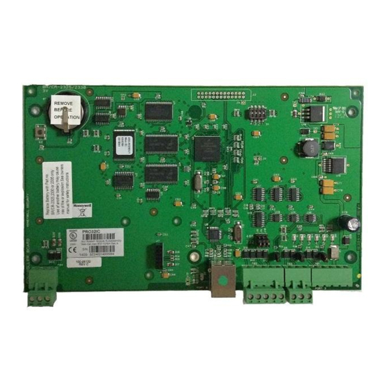
Page 16: Communications
(closed). Closing J1 provides the bus termination required. Wiring This section presents information on reader wiring, input wiring, and control output wiring. The following figure shows the PRO3200 board and identifies its terminal block pin assignments. PRO3200 Two-Reader Module Installation Guide, Document 800-15493... - Page 17 Installing the PRO3200 Two-Reader Module Wiring Figure 1: PRO3200 Two-Reader Module Wiring: Connectors 1-7 Short Door Status TWO READER BOARD BLACK together* Switch IN4 COMMON WHITE Egress GREEN Push-Button Switch IN5 COMMON Typical Connection IN0 COMMON IN1 COMMON RELAY0 NO...
- Page 18 Installing the PRO3200 Two-Reader Module Wiring Figure 2: PRO3200 Two-Reader Module Wiring: Connectors 1, 7-9 Tamper Switch (In CLOSE TWO READER BOARD position when +12VDC Power Cabinet Door is Supply Closed) C - No Charging N/C - No Charging N/C - Low Battery...
-
Page 19: Reader Wiring
Installing the PRO3200 Two-Reader Module Wiring Reader Wiring The following Honeywell reader module numbers have been approved by UL for use with the PRO32R2: OM40BHONA, OM55BHONA, OP10HONE, OP30HONE, OP40HONE, OP90HONE, OT30HONA, OT31HONA, OT35HONA, and OT36HONA. Each reader port supports a reader with TTL interface. Power to the reader is selectable as 5VDC or 12VDC (pass-through). -
Page 20: Input Wiring
(within 12 inches [30cm]); the effectiveness of the circuit decreases as the distance from the load increases. Only relays 0 and 2 can be used for door hardware in a UL installation. Note: PRO3200 Two-Reader Module Installation Guide, Document 800-15493... -
Page 21: Mounting Options
Use sufficiently large gauge of wires for the load current to avoid voltage loss. Mounting Options This board can be mounted on-edge in the rack-mount enclosure provided by Honeywell or it can be mounted flat against any surface using standoffs under the mounting holes provided in each of the four corners of this board. - Page 22 8. Recheck wiring for correct connections and continuity. 9. When all boards have been installed, connect the power supply cord for proper connections and power. 10.Set up the panel controls using the host software. PRO3200 Two-Reader Module Installation Guide, Document 800-15493...
-
Page 23: Pro3200 2-Reader Input Module Programming Sheet
PRO3200 2-Reader Input Module Programming Sheet Project Name Location / Country Host IC Board Board Description PW Panel RS485 Port Board Address Location Floor Cabinet Location Tamper Input Connected Powerfail Shunted Termination Jumper J1 Not Active PRO3200 Two-Reader Module Installation Guide, Document 800-15493... - Page 24 PRO3200 2-Reader Input Module Programming Sheet RS485 Port + Power Connected Cable Destination Conductor Connector Cable # Color RS485 TX ( + ) Pin #1 RS485 RX ( - ) Pin #2 Common Pin #3 Power Power Connected Cable Destination...
- Page 25 PRO3200 2-Reader Input Module Programming Sheet Reader 0 ProWatch Reader 0 (the reader address used in the Pro-Watch hardware setup) VDC Select J2 5 Volt Connected Cable Destination Conductor Cable # Color DC Out ( + ) Pin #1 Red LED...
- Page 26 PRO3200 2-Reader Input Module Programming Sheet Reader 2 ProWatch Reader 1 (the reader address used in the Pro-Watch hardware setup) VDC Select J2 5 Volt Connected Cable Destination Conductor Cable # Color DC Out ( + ) Pin #1 Red LED...
- Page 27 Honeywell Integrated Security 135 W. Forest Hill Avenue Oak Creek, WI 53154 United States 800-323-4576 414-766-1798 Fax www.honeywellaccess.com Specifications subject to change without notice. © Honeywell. All rights reserved. Document 800-15493...