
Related Manuals for Honeywell PRO32OUT


Summary of Contents for Honeywell PRO32OUT
- Page 1 PRO3200 Output Module (PRO32OUT) Installation Guide August 2013 © 2013 Honeywell International, Inc. All rights reserved. 800-15465...
- Page 2 All product and brand names are the service marks, trademarks, registered trademarks, or registered service marks of their respective owners. Printed in the United States of America. Honeywell reserves the right to change any information in this document at any time without prior notice.
-
Page 3: Table Of Contents
ONTENTS Notices Warnings and Cautions ..1 ....................Disclaimer ..2 .......................... Compliance ..3 ........................ - Page 4 (This page is left blank intentionally for double-sided printing.) www.honeywell.com...
-
Page 5: Notices
DO NOT ACCEPT VERBAL APPROVALS, BECAUSE THEY ARE NOT VALID. Honeywell never recommends using the PRO3200 or related products for use as a primary warning or monitoring system. Primary warning or monitoring systems should always meet local fire and safety code requirements. The installer must also test the system on a regular basis by instructing the end user in appropriate daily testing procedures. -
Page 6: Disclaimer
Customer harmless for any costs or damages including reasonable attorneys' fees which Customer may be required to pay as a result of the defective Product or the negligence of Honeywell, its agents, or its employees. -
Page 7: Compliance
Notices Compliance Customer shall hold harmless and indemnify Honeywell from and against all claims, demands, losses, and liability arising out of damage to property or injury to persons occasioned by or in connection with the acts or omissions of Customer and its agents and employees, and from and against all claims, demands, losses, and liability for costs of fees, including reasonable attorneys' fees, in connection therewith. -
Page 8: Shipping Instructions
All Products sold or licensed by Honeywell include a warranty registration card which must be completed and returned to Honeywell by or on behalf of the end user in order for Honeywell to provide warranty service, repair, credit or exchange. All warranty... -
Page 9: Confidentiality
Confidentiality All software, drawings, diagrams, specifications, catalogs, literature, manuals and other materials furnished by Honeywell relating to the design, use and service of the Products shall remain confidential and shall constitute proprietary rights of Honeywell and Customer agrees to treat such information as confidential. Customer shall acquire no rights in the design of the Products or the related materials except to use such information solely for the purpose of and only during the time it sells the Products. - Page 10 Notices Confidentiality (This page is left blank intentionally for double-sided printing.) www.honeywell.com...
-
Page 11: Installing The Pro3200 Output Module
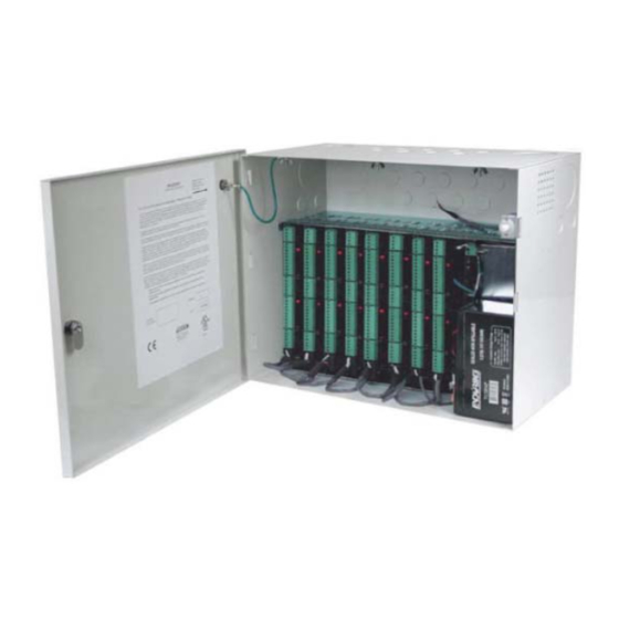
Installing the PRO3200 Output Module Description Installing the PRO3200 Output Module Description The Output Board provides connections for 16 relay outputs. You can either mount the board in a rack or open and flat. If you rack-mount the board, only one edge is accessible for wiring;... -
Page 12: Set Up
Table 1: PRO3200 Output Module Jumper Setting Jumper Setting Default Selected Port 1 RS-485 EOL terminator is not active Port 1 RS-485 EOL terminator is active Table 2: PRO3200 Output Module DIP Switch Settings Selection ADDRESS 0 ADDRESS 1* ADDRESS 2 ADDRESS 3 ADDRESS 4 www.honeywell.com... - Page 13 Installing the PRO3200 Output Module Set Up Table 2: PRO3200 Output Module DIP Switch Settings (continued) Selection ADDRESS 5 ADDRESS 6 ADDRESS 7 ADDRESS 8 ADDRESS 9 ADDRESS 10 ADDRESS 11 ADDRESS 12 ADDRESS 13 ADDRESS 14 ADDRESS 15 Reserved 9,600 BPS 19,200 BPS 38,400 BPS*...
-
Page 14: Led Operation
When any relay is energized or ON, its corresponding status LED turns ON also. The LED remains ON for as long as the relay is energized. The assignment for each relay status LED is shown in the following table. Table 4: Relay LEDs: 0-7 RELAY # Table 5: Relay LEDs: 8-15 RELAY # www.honeywell.com... -
Page 15: Power
Installing the PRO3200 Output Module Power The following table lists the LEDs D1 through D4. Table 6: LEDs 1-4 LED number Description Start power-up, hardware setup Testing RAM Tamper Power Power The Output Board accepts 12VDC with an operating range of 10 to 14VDC and consumes 385mA of current. -
Page 16: Wiring
0.1 second increments and be repeated up to 255 times. All 16 relays are rated for dry contact signal or load switching. While they are sized to handle typical loads, load switching can cause abnormal contact wear and premature www.honeywell.com... -
Page 17: Mounting Options
Mounting Options This board can be mounted on-edge in the rack-mount enclosure provided by Honeywell, or it can be mounted flat against any surface using standoffs under the mounting holes provided in each of the four corners of this board. -
Page 18: Wiring Diagram For Connectors 1 Through 8
RELAY8 NC RELAY9 NO RELAY9 C RELAY9 NC RELAY10 RELAY10 RELAY10 RELAY11 RELAY11 RELAY11 J 1 - RS-485 RS-485 TR+ CardRack PWR & Termination RS-485 TR- Com Harness* (Rack RS-485 GND Mount + 12V Only) * Rack Mount Configuration www.honeywell.com... -
Page 19: Wiring Diagram For Connectors 7 Through 10
Installing the PRO3200 Output Module Wiring Diagram for Connectors 7 through 10 Wiring Diagram for Connectors 7 through 10 Figure 2: PRO3200 Output Module: Connectors 7-10 Tamper Switch (In CLOSED 16 OUTPUT BOARD position when Cabinet Door is Closed) +12VDC Power C - No Charging N/C - No Charging RELAY12... - Page 20 Installing the PRO3200 Output Module Wiring Diagram for Connectors 7 through 10 (This page is left blank intentionally for double-sided printing.) www.honeywell.com...
- Page 21 Honeywell Access Systems 135 W. Forest Hill Avenue Oak Creek, WI 53154 United States 800-323-4576 414-766-1798 Fax www.honeywellaccess.com Specifications subject to change without notice. © 2013 Honeywell. All rights reserved. Document 800-15465...