Cisco Catalyst 9500 Series Hardware Installation Manual
Hide thumbs
Also See for Catalyst 9500 Series:
- Manual (360 pages) ,
- Configuration manual (223 pages) ,
- Hardware installation manual (102 pages)
Table of Contents
Table of Contents
Troubleshooting

Related Manuals for Cisco Catalyst 9500 Series


Summary of Contents for Cisco Catalyst 9500 Series
- Page 1 Cisco Catalyst 9500 Series Switches Hardware Installation Guide First Published: 2019-06-20 Last Modified: 2022-02-07 Americas Headquarters Cisco Systems, Inc. 170 West Tasman Drive San Jose, CA 95134-1706 http://www.cisco.com Tel: 408 526-4000 800 553-NETS (6387) Fax: 408 527-0883...
-
Page 2: Table Of Contents
Switch Models Front Panel SFP and QSFP Module Ports Port Mapping for Cisco Catalyst 9500 Series Switches Port Mapping for Cisco Catalyst 9500 Series High Performance Switches Port Mapping for Cisco Catalyst 9500X Series Switches RFID Tag Console Ports Management Port... - Page 3 Connecting to the Power Source Connecting to an AC Power Source Connecting to a DC Power Source Removing Power Supplies Finding the Serial Number Installing a Fan Module Fan Module Overview Installation Guidelines Cisco Catalyst 9500 Series Switches Hardware Installation Guide...
- Page 4 Port LEDs and Modes Beacon LED Fan LED Ethernet Management Port LED A P P E N D I X C Connector and Cable Specifications Connector Specifications 10/100/1000 Ports Module Connectors Console Cables Cisco Catalyst 9500 Series Switches Hardware Installation Guide...
- Page 5 23-Inch rack mount Accessory Kit for Cisco Catalyst 9500 High Performance Series 23-Inch Rack Mount Accessory Kit for Cisco Catalyst 9500X Series Extension Rails and Brackets for Four-Point Mounting for Cisco Catalyst 9500 Series Extension Rails and Brackets for Four-Point Mounting for Cisco Catalyst 9500 High Performance...
- Page 6 Contents Cisco Catalyst 9500 Series Switches Hardware Installation Guide...
- Page 7 Cisco has more than 200 offices worldwide. Addresses and phone numbers are listed on the Cisco website at www.cisco.com/go/offices. Cisco and the Cisco logo are trademarks or registered trademarks of Cisco and/or its affiliates in the U.S. and other countries. To view a list of Cisco trademarks, go to this URL: https://www.cisco.com/c/en/us/about/legal/trademarks.html.
-
Page 9: Preface
A vertical line, called a pipe, indicates a choice within a set of keywords or arguments. [x | y] Optional alternative keywords are grouped in brackets and separated by vertical bars. {x | y} Required alternative keywords are grouped in braces and separated by vertical bars. Cisco Catalyst 9500 Series Switches Hardware Installation Guide... - Page 10 Use the statement number provided at the end of each warning to locate its translation in the translated safety warnings that accompanied this device. Statement 1071 SAVE THESE INSTRUCTIONS Cisco Catalyst 9500 Series Switches Hardware Installation Guide...
-
Page 11: Related Documentation
Obtaining Documentation and Submitting a Service Request For information on obtaining documentation, submitting a service request, and gathering additional information, see the monthly What's New in Cisco Product Documentation, which also lists all new and revised Cisco technical documentation, at: http://www.cisco.com/c/en/us/td/docs/general/whatsnew/whatsnew.html... - Page 12 Preface Obtaining Documentation and Submitting a Service Request Cisco Catalyst 9500 Series Switches Hardware Installation Guide...
-
Page 13: Product Overview
C H A P T E R Product Overview The Cisco Catalyst 9500 Series Switches family consists of fixed core and aggregation layer switches supporting redundant power supplies and modular fans. The Cisco Catalyst 9500 Series offers switch models with downlink ports of the following types: •... -
Page 14: Switch Models
(SFP/SFP+) network module on uplink ports; and two power supply slots C9500-48X 40x10 Gigabit Ethernet SFP/SFP+ ports and 8x10 Gigabit Ethernet (SFP/SFP+) network module on uplink ports; and two power supply slots Cisco Catalyst 9500 Series Switches Hardware Installation Guide... -
Page 15: Front Panel
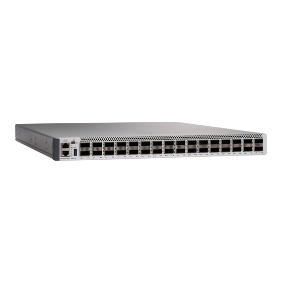
Product Overview Front Panel Front Panel Figure 1: Front Panel of a 24-Port Cisco Catalyst 9500 Switch 24 40G QSFP ports USB mini Type B console port RFID Mode button Console port (RJ-45 Serial) USB 2.0 host port Blue beacon LED... - Page 16 Product Overview Front Panel Figure 2: Front Panel of a Cisco Catalyst 9500 High Performance Switch (C9500-32C) 32 40G/100G QSFP28 ports RFID Ethernet management port Console port (RJ-45 Serial) Reset button USB 3.0 host port USB mini Type B console port...
- Page 17 Product Overview Front Panel Figure 3: Front Panel of a 48-Port Cisco Catalyst 9500 High Performance Switch (C9500-48Y4C) 48 1G/10G/25G SFP28 ports USB mini Type B console port Uplink ports RFID Ethernet management port Console port (RJ-45 Serial) Reset button USB 3.0 host port...
-
Page 18: Sfp And Qsfp Module Ports
SFP and QSFP Module Ports The SFP and QSFP modules provide copper or fiber-optic connections to other devices. The SFP and QSFP module ports for Cisco Catalyst 9500 Series Switches are as follows : Table 3: Cisco Catalyst 9500 Series Switch Models... -
Page 19: Port Mapping For Cisco Catalyst 9500 Series Switches
Network Modules, on page Support for Breakout Cables On Cisco Catalyst 9500 Series High Performance Switches, breakout cables are supported only on the C9500-32C model. Breakout cables enable a single 40G QSFP+ interface to be split into four 10G SFP+ interfaces and a single 100G QSFP28 interface into four 25G SFP28 interfaces. - Page 20 Product Overview Port Mapping for Cisco Catalyst 9500 Series Switches C9500-12Q Figure 4: 40G native port numbering Table 4: Port mapping for C9500-12Q 40-Gigabit native ports Configurable 10-Gigabit ports with Breakout Cable 1, 2, 3, and 4 5, 6, 7, and 8...
- Page 21 Product Overview Port Mapping for Cisco Catalyst 9500 Series Switches Table 5: Port mapping for C9500-24Q 40-Gigabit native ports Configurable 10-Gigabit ports with Breakout Cable 1, 2, 3, and 4 5, 6, 7, and 8 9, 10, 11, and 12...
-
Page 22: Port Mapping For Cisco Catalyst 9500 Series High Performance Switches
1, 2, 3, and 4 5, 6, 7, and 8 Port Mapping for Cisco Catalyst 9500 Series High Performance Switches The following figures show how the ports are numbered on different Cisco Catalyst 9500 Series High Performance Switches. C9500-32C Figure 8: Native Port Numbering for C9500-32C... - Page 23 Product Overview Port Mapping for Cisco Catalyst 9500 Series High Performance Switches All the 32 ports can be configured as 100G or 40G. Port Type Port Number on the Switch 100G native ports 1—32 40G native ports 1—32 Breakout is supported only on 24 ports of the C9500-32C switch model. Every 4th port of C9500-32C does not support breakout due to ASIC limitation.
- Page 24 Product Overview Port Mapping for Cisco Catalyst 9500 Series High Performance Switches C9500-32QC Figure 9: Native Port Numbering for C9500-32QC Port Type Port Number on the Switch 40G native ports 1—32 100G native ports 33—48 The 40G ports on this switch can be configured to function as 100G ports using the Command Line Interface (CLI).
-
Page 25: Port Mapping For Cisco Catalyst 9500X Series Switches
Port Mapping for Cisco Catalyst 9500X Series Switches Port Mapping for Cisco Catalyst 9500X Series Switches The following figures show how the ports are numbered on different Cisco Catalyst 9500X Series Switches. C9500X-28C8D Figure 12: Native Port Numbering for C9500X-28C8D... -
Page 26: Rfid Tag
• USB-C console port If you use the USB mini-Type B or USB-C console ports, the Cisco Windows USB device driver must be installed on any PC connected to the console port (for operation with Microsoft Windows). Mac OS X or Linux do not require special drivers. -
Page 27: Management Port
The USB host ports are located on different sides of the switches as follows: • Cisco Catalyst 9500 Series Switches: USB 2.0 port on the front panel and USB 3.0 port on the rear panel. • Cisco Catalyst 9500 Series High Performance Switches: USB 3.0 port on the front panel. -
Page 28: Mode Button
This functionality is available only on Cisco Catalyst 9500 Series Switches. Each 40G port can be configured to function as a 10G port using a Cisco QSFP to four SFP Active Optical Breakout Cables that connect a 40G QSFP port of the switch on one end to four 10G SFP ports of the switch on the other end. - Page 29 Figure 16: Rear Panel of a Cisco Catalyst 9500 High Performance Switch (C9500-32C) Power supply modules Grounding pad Fan modules SATA SSD module Figure 17: Rear Panel of a Cisco Catalyst 9500 High Performance Switch (C9500-32QC, C9500-48Y4C, and C9500-24Y4C) Power supply modules Fan modules Grounding pad SATA SSD module...
-
Page 30: Sata Ssd Module
6 fan modules SATA SSD Module To support the storage needs on the switch, the Cisco Catalyst 9500 Series High Performance Switches and Cisco Catalyst 9500X Series Switches provide support for pluggable Serial Advanced Technology Attachment (SATA) Solid State Drive (SSD) module. The SSD module storage capacity ranges are 240GB, 480GB and 960GB. -
Page 31: Fan Modules
The switch supports field-replaceable, variable-speed modular fans with default front-to-back airflow. The Cisco Catalyst 9500X Series Switches also support fan modules with back-to-front airflow. These fan units support Online Insertion and Removal (OIR) for up to 120 seconds. The fan unit is responsible for cooling the entire chassis and interfacing with environmental monitors to trigger alarms when conditions exceed thresholds. - Page 32 Product Overview Fan Modules Cisco Catalyst 9500 Series Switches Hardware Installation Guide...
-
Page 33: Installing A Switch
Power supplies that are ordered with the switch are preinstalled in the switch. If ordered separately, install the power supplies. Installing a network module Install the network modules on the network module slots. Cisco Catalyst 9500 Series Switches Hardware Installation Guide... -
Page 34: Safety Warnings
(such as power supplies, fans, or cards); these types of handles are not designed to support the weight of the unit. Statement 1032 Warning Hazardous voltage or energy is present on the backplane when the system is operating. Use caution when servicing. Statement 1034 Cisco Catalyst 9500 Series Switches Hardware Installation Guide... -
Page 35: Contents Of The Shipping Box
Statement 1051 Contents of the Shipping Box The shipping box contains the model of the switch you ordered and other components needed for installation. Some components are optional, depending on your order. Cisco Catalyst 9500 Series Switches Hardware Installation Guide... - Page 36 Installing a Switch Contents of the Shipping Box Figure 19: Components Delivered in the Shipping Box of Cisco Catalyst 9500 Series Switches Cisco Catalyst 9500 Series switch with Two M4.0 x 20mm Phillips pan-head optional network module (power supply screws (Black color)
- Page 37 Installing a Switch Contents of the Shipping Box Figure 20: Components Delivered in the Shipping Box of Cisco Catalyst 9500 Series High Performance Switches Cisco Catalyst 9500 Series High Ground lug and two M4.0 x 8mm Phillips Performance switch with optional network...
- Page 38 (Optional) USB console cable Two M4.0 x 20mm Phillips pan-head screws (Black color) Figure 21: Components Delivered in the Shipping Box of Cisco Catalyst 9500X Series Switches Cisco Catalyst 9500X Series switch One M4.0 x 20mm Phillips pan-head (power supply and fan modules not shown)
-
Page 39: Spare Accessory Kits
2. The item is orderable. You can choose the type of AC cord as per your requirement. Spare Accessory Kits The following table describes the spare accessory kits supported on different switch models: Table 12: Spare Accessory Kits and Rack Mount Kits for Cisco Catalyst 9500 Series Switches Part Number Description... -
Page 40: Unpacking The Switch
• You must install the system ground connection with any other rack or system power ground connections that you make. The system ground connection is required if FXS modules are installed or if this equipment is installed in a U.S. or European Central Office. Cisco Catalyst 9500 Series Switches Hardware Installation Guide... -
Page 41: Required Tools And Equipment
• Wire-stripping tool to remove the insulation from the grounding wire. Connecting the System Ground To establish an earth ground for the chassis, you must attach a grounding cable from the chassis’ grounding lug to the rack. Cisco Catalyst 9500 Series Switches Hardware Installation Guide... - Page 42 • Secure the grounding lug to the chassis with two M4.0 x 8mm Phillips pan-head screws. Figure 22: Connecting the System Ground Ground lug and two M4.0x8mm Phillips pan-head screws • Secure the grounding bracket and the lug to the chassis with two M4.0x 6mm flat-head screws. Cisco Catalyst 9500 Series Switches Hardware Installation Guide...
-
Page 43: Installing The Switch
• between 23.48 inches and 39.43 inches for C9500-32QC, C9500-48Y4C AND C9500-24Y4C. • between 24.72 inches and 39.75 inches for C9500X-28C8D. • Ensure you read the Regulatory Compliance and Safety Information (RCSI) before installing the switch. Cisco Catalyst 9500 Series Switches Hardware Installation Guide... - Page 44 Statement 1006 Figure 24: Four Post Rack Mount Kit for Cisco Catalyst 9500 Series Switches This figure shows the four post rack mount kit for Cisco Catalyst 9500 Series Switches. You can order the optional brackets from your Cisco sales representative.
- Page 45 24 M4.0x6mm Phillips flat-head screws Figure 26: Four Post Rack Mount Kit for Cisco Catalyst 9500X Series Switches This figure shows the four post rack mount kit for Cisco Catalyst 9500X Series Switches. You can order the optional brackets from your Cisco sales representative.
- Page 46 Rack-Mounting Two 19-inch brackets Eight number-10 Phillips pan-head 0.625" long screws Extension rails and brackets for four-point 16 number-8 Phillips flat-head 0.312“ long mounting screws Eight number-12 Phillips pan-head 0.50" long screws Cisco Catalyst 9500 Series Switches Hardware Installation Guide...
- Page 47 Rack-Mounting Figure 27: 23-inch Rack Mount Kit for Cisco Catalyst 9500 Series Switches This figure shows the optional 23-inch rack mount kit for Cisco Catalyst 9500 Series Switches. You can order the kit from your Cisco sales representative. 23-inch rack mount bracket...
- Page 48 23-inch rack mount bracket Figure 29: 23-inch Rack Mount Kit for Cisco Catalyst 9500X Series Switches This figure shows the optional 23-inch rack mount kit for Cisco Catalyst 9500X Series Switches. You can order the kit from your Cisco sales representative.
-
Page 49: Attaching The Rack-Mount Brackets
Attach the rack-mount brackets to the switch. For Cisco Catalyst 9500 Series Switches, use number-8 Phillips flat-head 0.312“ long screws to attach the long side of the bracket to each side of the switch for the front, middle or rear mounting positions. - Page 50 Figure 33: Front Mounting position of Rack Mounting Brackets The following illustrations used are of a Cisco Catalyst 9500 High Performance Series Switch. Note that the number of screws used for 9500X and 9500 High Performance Series Switches are different. Cisco Catalyst 9500X Series Switches use 6 screws to install the bracket on one side of the switch.
- Page 51 Attaching the Rack-Mount Brackets Figure 34: Middle Mounting position of Rack Mounting Brackets Figure 35: Rear Mounting position of Rack Mounting Brackets Cisco Catalyst 9500 Series High 19-inch mounting brackets Performance switch Cisco Catalyst 9500 Series Switches Hardware Installation Guide...
-
Page 52: Mounting The Switch In A Rack
Figure 37: Attaching the Extension Rail on a Cisco Catalyst 9500 High Performance Series Switch Method to attach the extension rail on Cisco Catalyst 9500X Series Switches and Cisco Catalyst 9500 Series switches is similar. The only difference is that a C9500 switch uses 4 screws to attach the extension rail on to one side of the switch, whereas a C9500X switch uses 6 screws. - Page 53 Cable guide Phillips machine screws M4.0x20mm Phillips pan-head screws (Black color) Step 3 Secure the switch to the rack rails using the Number-12 or number-10 Phillips machine screws provided with the accessory kit. Cisco Catalyst 9500 Series Switches Hardware Installation Guide...
-
Page 54: After Switch Installation
• Verify port connectivity after connecting devices to the switch ports. The LED turns green when the switch and the attached device have a link. Cisco Catalyst 9500 Series Switches Hardware Installation Guide... -
Page 55: Installing A Network Module
This is supported on the following switch models: • C9500-16X • C9500-40X Blank Network Module Insert this blank module when the switch has no uplink ports (this is required for (NM-C4-10G-BLANK) sufficient air flow). Cisco Catalyst 9500 Series Switches Hardware Installation Guide... - Page 56 Installing a Network Module Network Module Overview Figure 40: C9500-NM-8X Network Module SFP module ports LEDs Figure 41: C9500-NM-2Q Network Module Cisco Catalyst 9500 Series Switches Hardware Installation Guide...
-
Page 57: Installing A Network Module In The Switch
• Do not remove the blank module from the slot unless you are installing an SFP/SFP+/SFP28/QSFP module. Either a module or a dust plug must be in the slot at all times. Cisco Catalyst 9500 Series Switches Hardware Installation Guide... - Page 58 Position the module face up to install it in the module slot. Slide the module into the slot until the back of the module faceplate is flush with the switch faceplate. Secure the network module in place by latch. Cisco Catalyst 9500 Series Switches Hardware Installation Guide...
-
Page 59: Removing A Network Module
To avoid authentication failure and non-detection of modules, wait for a minimum of 6-8 seconds between the online insertion and removal (OIR) of network modules. Procedure Step 1 Attach an ESD-preventive wrist strap to your wrist and to an earth ground surface Cisco Catalyst 9500 Series Switches Hardware Installation Guide... -
Page 60: Finding The Network Module Serial Number
Place the module that you removed in an antistatic bag or other protective environment. Finding the Network Module Serial Number If you contact Cisco Technical Assistance regarding a network module, you need to know its serial number. Figure 44: Network Module Serial Number Location... -
Page 61: Installing Field Replaceable Units
Part Number Description C9K-PWR-650WAC-R 650W AC Power Supply PWR-C4-950WAC-R 950W AC Power Supply C9K-PWR-1500WAC= 1500W AC Power Supply C9K-PWR-1600WAC-R 1600W AC Power Supply C9K-PWR-930WDC-R 930W DC Power Supply C9-PWR-950WDC-R 950W DC Power Supply Cisco Catalyst 9500 Series Switches Hardware Installation Guide... - Page 62 Part Number Description C9K-PWR-1500WDC= 1500W DC Power Supply C9K-PWR-1600WDC-R 1600W DC Power Supply Figure 45: Cisco Catalyst 650W AC Input Power Supply Power cord retainer Release latch PSU fan Retainer clips AC power cord connector Power status and power supply failure...
- Page 63 Installing Field Replaceable Units Power Supply Overview Figure 46: Cisco Catalyst 950W AC Input Power Supply PSU LED Power cord retainer AC input connector Release handle Release latch PSU fan Cisco Catalyst 9500 Series Switches Hardware Installation Guide...
- Page 64 Installing Field Replaceable Units Power Supply Overview Figure 47: Cisco Catalyst 1600W AC Input Power Supply PSU fan Release latch Release handle Retainer clips Cable tie AC input connector Figure 48: Cisco Catalyst 1500W AC Input Power Supply Cisco Catalyst 9500 Series Switches Hardware Installation Guide...
- Page 65 Power Supply Overview PSU fan AC input connector Power cord retainer PSU LED Release latch Release handle Figure 49: Cisco Catalyst 950W DC Input Power Supply DC input connector PSU LED Release handle Grounding terminal PSU fan Release latch Cisco Catalyst 9500 Series Switches Hardware Installation Guide...
- Page 66 Installing Field Replaceable Units Power Supply Overview Figure 50: Cisco Catalyst 1600W DC Input Power Supply PSU fan Release handle DC input connector Release latch PSU LED Retainer clips Figure 51: Cisco Catalyst 1500W DC Input Power Supply PSU fan...
- Page 67 Power Supply Overview Release handle Figure 52: Power Supply Slot Cover for Cisco Catalyst 9500 Series Switches Release handles Figure 53: Power Supply Slot Cover for Cisco Catalyst 9500 High Performance C9500-32C Switch Model Cisco Catalyst 9500 Series Switches Hardware Installation Guide...
- Page 68 Installing Field Replaceable Units Power Supply Overview Figure 54: Power Supply Slot Cover for Cisco Catalyst 9500 High Performance C9500-32QC, C9500-48Y4C and C9500-24Y4C Switch Models Figure 55: Power Supply Slot Cover for Cisco Catalyst 9500X Series Switches Cisco Catalyst 9500 Series Switches Hardware Installation Guide...
-
Page 69: Installation Guidelines
PSU 12V main output is off and 12V aux output is on. Installation Guidelines • The switch chassis must be installed in a cabinet or rack that is secured to the data center. Cisco Catalyst 9500 Series Switches Hardware Installation Guide... -
Page 70: Installing Power Supply
Before performing any of the following procedures, ensure that power is removed from the DC circuit. Statement 1003 Installing Power Supply Inserting the Power Supply To insert the power supply into the chassis, follow these steps: Cisco Catalyst 9500 Series Switches Hardware Installation Guide... -
Page 71: Connecting To The Power Source
You use one power cord for each power supply to connect the power supply to its power source. Connecting to an AC Power Source To connect to a power source, follow these steps: Cisco Catalyst 9500 Series Switches Hardware Installation Guide... -
Page 72: Connecting To A Dc Power Source
If the unconnected end of each power cable is not stripped off of its insulation for the last 0.75 inches (19 mm), use wire strippers to remove that amount of insulation. Cisco Catalyst 9500 Series Switches Hardware Installation Guide... - Page 73 Positive terminal Negative terminal • If you are using PWR-C4-950WDC-R, do the following: a. Remove the safety cover on the terminal box on the front of the DC power supply. Cisco Catalyst 9500 Series Switches Hardware Installation Guide...
- Page 74 Loosen and unscrew the two nuts on the terminal box. The terminal box has two slots for power terminals. Each terminal has a nut that you use to fasten the power cable to the terminal. Cisco Catalyst 9500 Series Switches Hardware Installation Guide...
- Page 75 When you first activate the power supply, you can verify the functionality of the LED by checking that LED turns on for a couple of seconds. If the LED is flashing amber or red, check the power connections on the power supply and the power source. Cisco Catalyst 9500 Series Switches Hardware Installation Guide...
-
Page 76: Removing Power Supplies
Finding the Serial Number If you contact Cisco Technical Assistance, you need to know the serial number. These figures show where the serial number is located. You can also use the show inventory EXEC command to see the serial number. -
Page 77: Installing A Fan Module
Installing a Fan Module Fan Module Overview Depending on the switch model, five individual fan modules (C9500-32C and Catalyst 9500 Series switches), two fan trays with dual-stacked fans (C9500-24Y4C, C9500-48Y4C and C9500-32QC) or six individual fan modules (C9500X-28C8D) are available. In models using 5 fan modules, the switch can operate with 4 operational fans and 1 nonfunctional fan and in models using 6 fan modules, the switch can operate with 5 operational fans and 1 nonfunctional fan. - Page 78 Note that -R in the part number indicates reverse airflow (front-to-back) and -F indicates forward airflow (back-to-front). Figure 60: FAN-T4-R Fan Module and C9K-T2-FANTRAY= Fan assembly levers Fan LED Fan assembly retention latch Cisco Catalyst 9500 Series Switches Hardware Installation Guide...
- Page 79 Figure 61: Fan Tray Unit with Dual-Stacked Fans Fan LED Fan assembly retention latch Fan assembly levers Fans C9500X-FAN-1U-R or C9500X-FAN-1U-F Figure 62: Fan Tray Unit with Dual-Stacked Fans Fan LED Fan assembly retention latch Cisco Catalyst 9500 Series Switches Hardware Installation Guide...
-
Page 80: Installation Guidelines
When the fan is operating, a green LED is on in the top left corner of the fan. Do not reach into a vacant slot when installing or removing a module. Exposed circuitry is an energy Warning hazard. Statement 206 Cisco Catalyst 9500 Series Switches Hardware Installation Guide... - Page 81 Installing a Fan Module Figure 63: Installing the Fan Module on a Cisco Catalyst 9500 Series Switch Figure 64: Installing the Fan Module on Cisco Catalyst 9500 High Performance C9500-32C Switch Model Cisco Catalyst 9500 Series Switches Hardware Installation Guide...
-
Page 82: Finding The Fan Module Serial Number
Installing Field Replaceable Units Finding the Fan Module Serial Number Figure 65: Installing the Fan Module on Cisco Catalyst 9500 High Performance C9500-32QC, C9500-48Y4C and C9500-24Y4C Switch Models Finding the Fan Module Serial Number If you contact Cisco Technical Assistance regarding a fan module, you need to know the fan module serial number. - Page 83 Installing Field Replaceable Units Finding the Fan Module Serial Number Figure 66: Fan Module Serial Number on Cisco Catalyst 9500 Series switches, High Performance Switch C9500-32C Switch and Cisco Catalyst 9500X Series C9500X-28C8D Switch Models Figure 67: Fan Module Serial Number on Cisco Catalyst 9500 High Performance C9500-32QC, C9500-48Y4C and C9500-24Y4C Switch...
-
Page 84: Installing An Ssd Module
Figure 68: SATA SSD Supported on Cisco Catalyst 9500 Series High Performance Switches Status LED Blue beacon LED Hot-swap button The following table lists the SATA SSD modules supported on Cisco Catalyst 9500 Series High Performance Switches. Cisco Catalyst 9500 Series Switches Hardware Installation Guide... -
Page 85: Installing An Ssd Module
Cisco Catalyst 9500 Series 480GB SATA memory C9K-F1-SSD-960G Cisco Catalyst 9500 Series 960GB SATA memory Figure 69: SSD Supported on Cisco Catalyst 9500X Series Switches The following table lists the SSD modules supported on Cisco Catalyst 9500X Series Switches. SSD Module Description C9K-F3-SSD-240GB= Cisco pluggable SSD storage –... - Page 86 On C9500X switches, secure the SSD module to the chassis using the two screws provided. Step 4 On Cisco Catalyst 9500 Series High Performance Switches, verify that the LED on the SSD module turns solid green. Cisco Catalyst 9500 Series Switches Hardware Installation Guide...
-
Page 87: Removing An Ssd Module
Step 1 Depending on your switch model, do one of the following: • On Cisco Catalyst 9500 Series High Performance switches, press and hold the hot-swap button on the SSD module for atleast four seconds. The system powers down the SSD module and the port and the LED turns off indicating that the module is ready for removal. - Page 88 Installing Field Replaceable Units Removing an SSD Module Cisco Catalyst 9500 Series Switches Hardware Installation Guide...
-
Page 89: Troubleshooting
The switch consists of these subsystems: • Power supplies • Fan tray assembly Cisco Catalyst 9500 Series Switches Hardware Installation Guide... -
Page 90: Identifying Startup Problems
If this unit has more than one power cord, repeat Step 1 for each power supply. If the Power Supply LED still fails to light when the switch is connected to a different power source with a new power cord, the power supply is probably faulty. Cisco Catalyst 9500 Series Switches Hardware Installation Guide... -
Page 91: Troubleshooting The Fan Tray
If you are unable to solve a startup problem after using the troubleshooting suggestions in this chapter, contact a Cisco customer service representative for assistance and additional instructions. Before you call, have the following information ready to help your service provider assist you as quickly as possible:... -
Page 92: Finding The Serial Number
Finding the Serial Number If you contact Cisco Technical Assistance, you need to know the switch serial number. The figure shows where the serial number is located. You can also use the show version privileged EXEC command to see the serial number. - Page 93 MAC Number Compliance label Figure 73: Serial Number Location and Switch Labels on Cisco Catalyst 9500 High Performance Series Switches Serial number of the switch is located at the top of the switch. Following illustration shows all the labels at the top and the bottom of the switch.
- Page 94 Troubleshooting Finding the Serial Number Figure 74: Serial Number Location Cisco Catalyst 9500X Series Switches Cisco Catalyst 9500 Series Switches Hardware Installation Guide...
-
Page 95: Appendix A Technical Specifications
C9500X-FAN-1U-F fans Storage temperature • -4°F to 149°F (-20°C to 65°C) • -40°F to 158° F (-40°C to 70°C) for Cisco Catalyst 9500X Series Switches Relative humidity • Operating : 5 to 90% (noncondensing) • Non-Operating : 5% to 95% (noncondensing) - Page 96 1.73 x 17.5 x 18.0 in. (4.4 x 44.5 x 45.7 cm) C9500-32QC C9500-48Y4C C9500-24Y4C C9500X-28C8D 1.73 x 17.5 x 21.8 in. (4.4 x 44.5 x 55.4 cm) Rack units (RU) 1 RU Cisco Catalyst 9500 Series Switches Hardware Installation Guide...
- Page 97 C9500X-28C8D This table describes the power requirements. Table 18: Power Requirements Power Requirements Input Voltage 115 to 230 VAC C9500-12Q C9500-16X C9500-24Q C9500-40X 90 to 264 VAC C9500-32C C9500-32QC C9500-48Y4C C9500-24Y4C C9500X-28C8D Cisco Catalyst 9500 Series Switches Hardware Installation Guide...
- Page 98 Technical Specifications Technical Specifications Cisco Catalyst 9500 Series Switches Hardware Installation Guide...
-
Page 99: Understanding The Leds
Power Supply LEDs, on page 95 • Port LEDs and Modes, on page 95 • Beacon LED, on page 97 • Fan LED, on page 98 • Ethernet Management Port LED, on page 98 Cisco Catalyst 9500 Series Switches Hardware Installation Guide... -
Page 100: Led Indicators
Understanding the LEDs LED Indicators LED Indicators Figure 75: LEDs on Cisco Catalyst 9500 Series Switches System LED Power Supply Unit(PSU) LED Blue beacon LED Fan LED 10G Status LEDs Ethernet Management port LED Available only on switches with 10G ports. - Page 101 LEDs on Cisco Catalyst 9500X Series Switches Cisco Catalyst 9500X Series Switches have LEDs on the front and the rear panel of the chassis. Following illustration helps you identify the various LEDs available on the front and the rear panel of the switch.
- Page 102 Power Supply Unit (PSU) LED Figure 78: LEDs on the Rear Panel System LED Ethernet Management port link status LED Blue beacon LED Ethernet Management port link activity LED SSD LED Fan LED Cisco Catalyst 9500 Series Switches Hardware Installation Guide...
-
Page 103: System Led
For example, if you press the Mode button on the active switch to show the SPEED LED, all the other switches in the stack also show the SPEED LED. Cisco Catalyst 9500 Series Switches Hardware Installation Guide... - Page 104 Network module slots Port is not operating. Blinking green Port is operating at up to 10 Gb/s. DUPLX (duplex) Port is operating in half duplex. Green Port is operating in full duplex. Cisco Catalyst 9500 Series Switches Hardware Installation Guide...
-
Page 105: Beacon Led
Member numbers of other stack member switches. Cisco Catalyst 9500 Series High Performance Switches The port LEDs on the Cisco Catalyst 9500 Series High Performance Switches display only the port status. Table 23: Meaning of Switch LED Colors for Port Status LED... -
Page 106: Fan Led
Table 25: Ethernet Management Port Link Activity LED Color Description Blinking green Link is up. Link is down. Table 26: Ethernet Management Port Link Status LED Color Description Solid green Link is up. Link is down. Cisco Catalyst 9500 Series Switches Hardware Installation Guide... -
Page 107: Connector And Cable Specifications
All 10/100/1000 ports use standard RJ-45 connectors and Ethernet pinouts. Figure 79: 10/100/1000 Port Pinouts Module Connectors This section describes the different SFP/QSFP/QSFP-DD module connectors used on 10G/25G/40G/100G/400G ports on the switches. Cisco Catalyst 9500 Series Switches Hardware Installation Guide... -
Page 108: Console Cables
The USB console port uses a USB Type A to 5-pin mini-Type B cable and a USB Type A to Type C cable. These cables are not supplied with the switch; you have to order them separately. Cisco Catalyst 9500 Series Switches Hardware Installation Guide... -
Page 109: Cables And Adapters
Each port must match the wavelength specifications on the other end of the cable, and the cable must not exceed the stipulated cable length. Copper 1000BASE-T SFP module transceivers use standard four twisted-pair, Category 5 cable at lengths up to 328 feet (100 meters). Cisco Catalyst 9500 Series Switches Hardware Installation Guide... -
Page 110: Cable Pinouts
The wire connected to the pin on the outside of the left plug should be a different color from the wire connected to the pin on the inside of the right plug. Cisco Catalyst 9500 Series Switches Hardware Installation Guide... -
Page 111: Console Port Adapter Pinouts
Switch Console Port (DTE) RJ-45-to-DB-9 Terminal Adapter Console Device Signal DB-9 Pin Signal Table 28: Console Port Signaling with a DB-25 Adapter Switch Console Port (DTE) RJ-45-to-DB-25 Terminal Adapter Console Device Signal DB-25 Pin Signal Cisco Catalyst 9500 Series Switches Hardware Installation Guide... - Page 112 Connector and Cable Specifications Connector and Cable Specifications Switch Console Port (DTE) RJ-45-to-DB-25 Terminal Adapter Console Device Signal DB-25 Pin Signal Cisco Catalyst 9500 Series Switches Hardware Installation Guide...
-
Page 113: Configuring The Switch
Putty or TeraTerm, makes communication between the switch and your PC or terminal possible. Step 3 Configure the baud rate and character format of the PC or terminal to match the console port default characteristics: Cisco Catalyst 9500 Series Switches Hardware Installation Guide... -
Page 114: Connecting The Usb Console Port
If you are connecting the switch USB console port to a Windows-based PC for the first time, install the USB driver. See Installing the Cisco Microsoft Windows USB Device Driver, on page 106. USB Type A port on the switch provides file system support and is NOT a console port. See USB Note Type A Port section. -
Page 115: Installing The Cisco Microsoft Windows Usb Driver
Installing the Cisco Microsoft Windows USB Driver Procedure Step 1 Obtain the Cisco USB console driver file from the Cisco.com web site and unzip it. You can download the driver file from the Cisco.com site for downloading the switch software. Note Windows 10 includes a USB to RS232 driver. - Page 116 Configuring the Switch Uninstalling the Cisco Microsoft Windows USB Driver Cisco Catalyst 9500 Series Switches Hardware Installation Guide...
-
Page 117: Accessory Kit Contents
19-Inch Rack Mount Accessory Kit for Cisco Catalyst 9500 Series, on page 109 • 19-Inch Rack Mount Accessory Kit for Cisco Catalyst 9500 High Performance Series , on page 110 • 19-Inch Rack Mount Accessory Kit for Cisco Catalyst 9500X Series Switches , on page 110 •... -
Page 118: 19-Inch Rack Mount Accessory Kit For Cisco Catalyst 9500 High Performance Series
M4.0 x 8mm Phillips pan-head screws Disposable ESD strap 19-Inch Rack Mount Accessory Kit for Cisco Catalyst 9500X Series Switches The 19-inch rack mount accessory kit for Cisco Catalyst 9500X Series Switches contains the following items: Item Quantity 19-inch mounting brackets Cable guides Number-12 pan-head 0.50"... -
Page 119: 23-Inch Rack Mount Accessory Kit For Cisco Catalyst 9500 Series
Quantity M4.0 x 6mm flat-head screws Disposable ESD strap 23-Inch Rack Mount Accessory Kit for Cisco Catalyst 9500 Series The 23-inch Rack Mount Accessory Kit for Cisco Catalyst 9500 Series contains the following items: Item Quantity 23-inch mounting brackets 19-inch mounting brackets Number-12 pan-head 0.50"... -
Page 120: Extension Rails And Brackets For Four-Point Mounting For Cisco Catalyst 9500 Series
M4.0 x 6mm Phillips flat-head screws Number-10 pan-head 0.625" long screws Extension Rails and Brackets for Four-Point Mounting for Cisco Catalyst 9500 Series The Extension Rails and Brackets for Four-Point Mounting Accessory Kit for Cisco Catalyst 9500 Series contains the following items: Item Quantity... -
Page 121: Extension Rails And Brackets For Four-Point Mounting For Cisco Catalyst 9500X Series Switches
Extension Rails and Brackets for Four-Point Mounting for Cisco Catalyst 9500X Series Switches Extension Rails and Brackets for Four-Point Mounting for Cisco Catalyst 9500X Series Switches The extension rails and brackets for four-point mounting accessory kit for Cisco Catalyst 9500X Series Switches contains the following items: Item... - Page 122 Accessory Kit Contents Extension Rails and Brackets for Four-Point Mounting for Cisco Catalyst 9500X Series Switches Cisco Catalyst 9500 Series Switches Hardware Installation Guide...