Quick Links
HW-AV-LTE-M
CLSS Pathway
Quick Start Guide
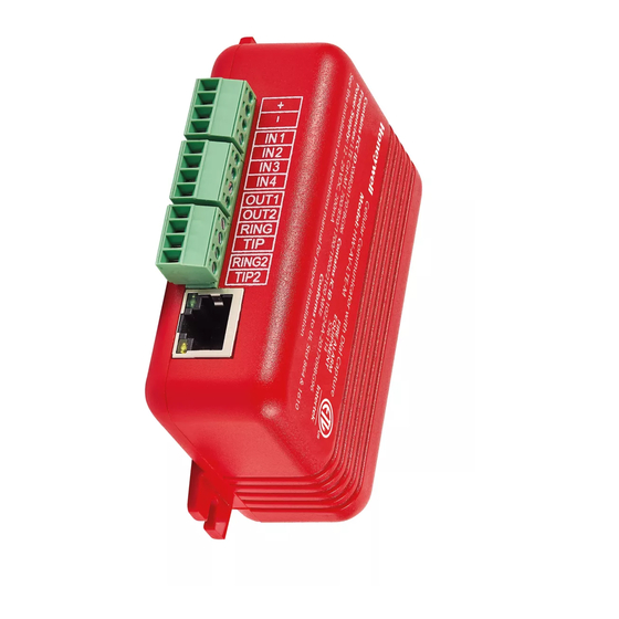
The CLSS Pathway (HW-AV-LTE-M) is a dual-path cellular
communicator. It transmits data from a fire panel to a central
monitoring station. It can communicate over AT&T as well as
Verizon LTE networks.
Other Features
The communicator also has other features, including secondary
data transmission via an Ethernet connection as well as
monitoring dry-contact relay outputs.
Information Sources
For more detailed procedures and all configuration options:
Installation and Operations Manual (LS10340-000HW-E)
To install in the enclosure (HW-AV-ENC) and wire for dialer
capture or relay monitoring:
Product Installation Document (LS10338-000HW-E)
To access the most updated versions of all product
documentation, log on to CLSS Site Manager and access the help
section.
Instructions for obtaining a CLSS account are in the
a CLSS Account for Your Organization
A. Receiving a CLSS Account for Your Organization
Configuring the CLSS Pathway requires a CLSS account. If you
already have the CLSS account, then proceed to section
Assigning the Device to a
To request a CLSS Account, please visit
scan the QR code below for instructions to request a CLSS
Account:
Your organization's Administrator should perform this activity.
An Administrator is someone who can sign on behalf of the
organization.
After receiving your CLSS account, add your Customers and
Employees in the CLSS Site Manager. Please refer to the help
section of CLSS Site Manager for more information.
B. Assigning the Device to a Customer
This step is required to associate your device with a CLSS Site
and Building for your Customer.
1. Log into the CLSS mobile App.
2. Tap the three dots at the top-right corner of the dashboard and
then tap Install Dialer Capture.
3. Follow the on-screen instructions.
C. Configuring Central Station Alerting for the Device
C.1. Adding a Central Station to Your CLSS Account.
be completed by the organization's Administrator. This is a one-
time task for each central station.
1. Log into the CLSS Site Manager.
2. Click your profile icon at the top-right corner and select
External Accounts.
3. Click ADD NEW in the External Accounts page, under
Central Stations section.
4. Follow the on-screen instructions.
C.2. Assigning a Central Station Account to the Device.
associates your central station account details for the specific site
with the device you are configuring.
1. Log into CLSS Site Manager.
2. Navigate to the Customer > Site in the CLSS Site Manager,
where the device is installed.
3. Click the Feature Activation icon on the left sidebar.
4. Click the CLSS Pathway section at the left and then click on
the respective device to see details.
5. Click Configure Central Station Alerting in the details
view.
6. Follow the on-screen instructions.
ECN: 00004957 | P/N: LS10339-000HW-E | Rev. A | September, 2021
section below.
Customer.
fire.honeywell.com
This step must
D. Programming the Connected Panel
Program according to the panel's programming document.
•
Enabling the PSTN dialer of the panel
•
Selecting the DTMF mode (for tone dialing)
•
Selecting the Contact ID communication format
•
Providing any telephone number for dialing. Ex: 999999
•
Entering the 4-digit account number
E. Mounting the Communicator
You can mount the communicator within a UL-listed enclosure,
or optionally, within the HW-AV-ENC.
Warnings
•
Before mounting and wiring, ensure that the panel is powered
down.
•
Only a regulated UL-Listed UOJZ, UTOU, or NBSX control
panel or power supply should power the communicator.
•
The communicator must be connected to a UL-Listed
compatible panel with power limited circuits.
A. Receiving
•
Install the communicator only at a dry indoor location.
•
The location and wiring methods must be in accordance with
the National Electrical code, ANSI/NFPA 70.
•
Install in accordance with the National Fire Alarm and
B.
Signaling Code, NFPA 72.
To Mount the Communicator
or
Mount the communicator and wire for dialer connections as in
the Figure 2: The Wiring Diagram.
For UL installations, secure the communicator to a
UL-listed enclosure, such as a UL-listed junction box.
Enclosure should be close nipple to the fire alarm
control panel.
1. Check that you have the communicator, 3ft antenna, and this
Quick Start Guide from the carton box.
2. In this Quick Start Guide, locate the installation sticker in the
Serial Number and Configuration Key section. It is at the
bottom right of the last page.
3. Check that the sticker has the serial number and the
configuration key to program the communicator.
4. Place the sticker on the inside lid of the enclosure.
5. If using the HW-AV-ENC, mount the enclosure onto the two
mounting holes as in Figure 1 and secure it with the hardware
supplied with the enclosure.
For other enclosures, use the communicator box' mounting
flanges as a template to drill holes for appropriate sized
mounting hardware. (Not supplied).
6. Slide the box onto these screws and tighten the screws.
This step
Figure 1: Mounting the Communicator
1

Related Manuals for Honeywell HW-AV-LTE-M


Summary of Contents for Honeywell HW-AV-LTE-M
- Page 1 HW-AV-LTE-M CLSS Pathway Quick Start Guide The CLSS Pathway (HW-AV-LTE-M) is a dual-path cellular D. Programming the Connected Panel communicator. It transmits data from a fire panel to a central Program according to the panel’s programming document. monitoring station. It can communicate over AT&T as well as •...
- Page 2 ETL Listed Communicator. Control No. 5013005 Connect to GND of the Communicator. UL Standards The HW-AV-LTE-M is designed to comply with UL 864 - Control Units and Primary RING Connect to RING of the Communicator. Accessories for Fire Alarm Systems Units Dialer Connect to TIP of the Communicator.