Honeywell HCE80R Mounting And Operation Instructions
Hide thumbs
Also See for HCE80R:
- Installation and operation manual (34 pages) ,
- Mounting and operation manual (94 pages)
Table of Contents
Table of Contents

Related Manuals for Honeywell HCE80R


Summary of Contents for Honeywell HCE80R
- Page 1 HCE80(R) / HCC80(R) Mounting and operation Montage en bedrijf...
- Page 2 English Nederlands...
- Page 3 HCE80(R) / HCC80(R) Mounting and operation Fig. 1 Fig. 2 Fig. 3 Power Mode Fig. 4 1 2 3 4 5 6 HRA80 Z4 Z5 Z6 Z7 Z8 Panter Smile Fig. 5 Fig. 6 Fig. 7 7 m m 5.5 mm 5.5 mm...
-
Page 5: Table Of Contents
HCE80(R) / HCC80(R) Mounting and operation Contents Introduction Help with problems System overview Changing the fuse Function overview Restoring the factory settings at the underfloor heating controller Mounting and installation Fault displays Errors and elimination Creating a zoning plan Zoning plan (sample) Options Safety instructions Boiler feedback... -
Page 6: Introduction
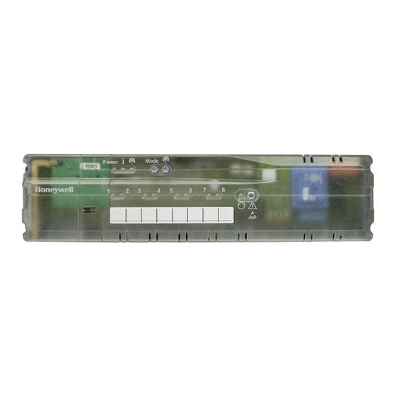
Introduction Introduction These installation and operating instructions contain all the information required for installation, commissioning and configuring the underfloor heating controller HCE80(R) / HCC80(R). All the operating elements and connections are shown on a fold-out page. Fold out the left-hand cover. Legend for fold-out page Leave the cover folded out while reading further. -
Page 7: System Overview
Central operating device (CM927) Controls the room temperature via Boiler feedback programmable time programs (1 zone) Analog output (only HCE80/HCC80) or relay output (only HCE80R/HCC80R) Room thermostat (DTS92) Measures the room temperature, Integrated pump relay room setpoint temperature can be set, with digital display... - Page 8 Introduction System overview – continued An underfloor heating control system can in principle have 3 different configurations: with an evohome controller with a central operating device CM927 without a central operating device This configuration determines the further procedure for commissioning and binding. DTS92A(E) HCW82 HCF82...
-
Page 9: Function Overview
Integrated pump relay Boiler feedback – Analog (only HCE80/HCC80) – Integrated relay with floating contact 42 V AC/VDC (only at HCE80R, HCC80R) – Wireless via relay BDR91 Underfloor heating controller can be switched between heating and cooling 1 antenna (internal or external) can... -
Page 10: Mounting And Installation
Mounting and installation Mounting and installation Creating a zoning plan Within a building rooms (zones) can be controlled with different room setpoint temperatures. The thermal actuators of the allocated zone (room) are controlled depending on the room setpoint temperature. Temperature Thermal actuators Number of zones (maximum) -
Page 11: Zoning Plan (Sample)
HCE80(R) / HCC80(R) Mounting and operation Zoning plan (sample) Zone Thermal actuator Room setpoint Room name Operating (type, location) generator (location) modes Heating Cooling* Heating Cooling* Heating Cooling* Heating Cooling* Heating Cooling* Heating Cooling* Heating Cooling* Heating Cooling* * Optional... -
Page 12: Safety Instructions
Mounting and installation Safety instructions CAUTION Insufficient data transfer DANGER Danger to life through electric shock! Interference of the radio receiver in the device Contacts that are through metallic objects open are live. and further radio devices. Unplug the power When mounting the plug before opening device ensure that... -
Page 13: Installing The Underfloor Heating Controller
HCE80(R) / HCC80(R) Mounting and operation Installing the underfloor heating controller The underfloor heating controller can be installed within or outside the distributor box. 4 4.2-mm holes for installation are located on the underfloor heating controller. Wall installation Mark, drill and insert plugs into fastening holes. Screw on the underfloor heating controller. -
Page 14: Settings At The Underfloor Heating Controller
Mounting and installation Settings at the underfloor heating controller DANGER! Danger to life through electric shock! Contacts that are open are live. Ensure that the cable is deenergized. Opening the housing Open the housing (see fold-out page, Fig. 2). Plugging in the expansion module (optional) The expansion module HCS80 expands the number of possible temperature zones of the underfloor heating controller from 5 to 8. -
Page 15: Cabling
HCE80(R) / HCC80(R) Mounting and operation Cabling Permissible cable types and lengths Connecting the power cable DANGER! Danger to life through Thermal actuators electric shock! Outer cable diameter min. 3.5 mm / max. 5.3 mm Contacts that are open are live. Cable length max. - Page 16 Mounting and installation Cabling – continued Connecting a pump (230 V AC) Connecting the thermal actuators As soon as a zone is active, the pump is activated with a time delay. The pump switches off as soon as all the valves are closed. The LED (see fold-out page, Fig.
-
Page 17: Commissioning
HCE80(R) / HCC80(R) Mounting and operation Installing an external antenna Commissioning Up to three underfloor heating controllers can be connected to an antenna. During commissioning, room setpoint generators/sensors and, if applicable, the Only install the external antenna outside time programs of the central operating metal housings (e.g. -
Page 18: Connecting Devices (Binding)
Connecting devices (binding) Connecting devices (binding) Binding room setpoint generators/sensors with the evohome controller DTS92A(E) HCW82 HCF82 With the evohome controller each zone can be controlled separately with an individual time program. For information on installing the device please read the evohome installation instructions. evotouch Option evohome controller... -
Page 19: Binding Room Setpoint Generators/Sensors
HCE80(R) / HCC80(R) Mounting and operation Commissiong and binding the evohome Binding a room setpoint generator/ controller sensor (HCW82 or HCF82) If you want to control the room temperature with Briefly press the bind button in the bottom the evohome controller (that has to be located right-hand corner. -
Page 20: Binding The Room Device Cm927 With The Underfloor Heating Controller
Connecting devices (binding) Binding the room device CM927 with the underfloor heating controller DTS92A(E) HCW82 HCF82 CM927 Each zone can be controlled with the same time program with the CM927 operating device. For information on installing the device please read the CM927 installation instructions. Option Activating the integrated room Setting the CM927 to the binding mode... -
Page 21: Binding The Underfloor Heating Controller Without Time Program
HCE80(R) / HCC80(R) Mounting and operation Binding the underfloor heating controller without time program DTS92A(E) HCW82 HCF82 The following section describes how you can assign (bind) the various components of a temperature zone. Option Setting the parameter SU at the room thermostat DTS92 The parameter SU:2 has to be set so that the room thermostat DTS92 can be assigned directly to the underfloor heating controller. - Page 22 Connecting devices (binding) Binding the underfloor heating controller without time program – continued Binding the room thermostat DTS92 with Binding the underfloor heating controller Press the installation button the underfloor heating controller Setting the underfloor heating twice (skip red flashing LED). controller to the binding mode The green LED of the next Keep the zoning plan at hand.
- Page 23 HCE80(R) / HCC80(R) Mounting and operation Binding room setpoint generators/sensors HCW82/HCF82 with the underfloor heating controller Setting the underfloor heating Binding controller to the binding mode Press the installation button at the Press and hold the installation underfloor heating controller again until button on the underfloor heating the red LED of the desired zone flashes.
-
Page 24: Cancelling The Assignment Of Zones (Rooms)
Connecting devices (binding) Cancelling the assignment of zones (rooms) Cancelling the assignment of a room Cancelling the assignment of the time setpoint generator/sensor of a zone program (room setpoint) of a zone Keep the installation button pressed Keep the installation button pressed for at least 2 seconds in order to for at least 2 seconds in order to... -
Page 25: Checking The Installation
HCE80(R) / HCC80(R) Mounting and operation Checking the installation Checking the configuration Test the radio communication Press the installation button Sending test signals LED flashes yellow. The colours of LEDs 1...8 indicate the configuration of the temperature zones. LEDs 1...8 Meaning The underfloor heating controller can send a test signal to all the allocated radio... -
Page 26: Help With Problems
Help with problems Help with problems Changing the fuse Restoring the factory settings at the underfloor heating controller Only use ceramic fuses of the type 230 V AC; 2.5 A; fast; 5 x 20 mm. When the underfloor heating controller is reset to the factory settings, the cur- rent configuration (assignment) is deleted. -
Page 27: Errors And Elimination
HCE80(R) / HCC80(R) Mounting and operation Errors and elimination Problem Cause/solution There is a fault in one of the The LED lights temperature zones (see Page 15). up red after Problem Cause/solution commissioning. Check the radio connection. Power LED does not Mains voltage not connected. -
Page 28: Options
The relay is switched on and off depending on the valve setting. Implementing a boiler feedback with an integrated relay 42 V AC, floating contact (only HCE80R/HCC80R) The relay is switched on and off depending on the valve setting. Strip the connections 5.5 mm (see fold-out page, Fig. -
Page 29: Cooling With Cm927
HCE80(R) / HCC80(R) Mounting and operation Cooling with CM927 Activating the cooling function at the CM927 Binding the room temperature setpoint cooling The heating/cooling function is specified by The cooling function at the CM927 has Parameter 4:HC in the installation mode. to be activated to this purpose. -
Page 30: Time Program For Cooling Function
Options Time program for cooling function If the cooling function was activated, a separate time program for heating and cooling can be assigned to each zone. Time programs and setpoint values are activated by the switchover contact heating or cooling. The time program for heating is active when the connection at Terminal 3 and 4 is open at Connector 9 (see fold-out page, Fig. -
Page 31: Appendix
HCE80(R) / HCC80(R) Mounting and operation Appendix Navigation and function overview Function Press button Zone LED Exit mode Status LED Normal mode Lights up green = Valve open LED off = Valve closed Binding Lights up yellow Flashing 4 min after last action >... -
Page 32: Technical Data
Declaration of conformity Dispose of the batteries according to the local statutory requirements and not with the used domestic refuse. Honeywell hereby declares that HCE80(R) / HCC80(R) complies with the basic requirements and other relevant regulations of guideline 1999/5/EC. The declaration of conformity of the product can be requested from the manufacturer.