
Related Manuals for Allen-Bradley Bulletin 1203 Series


Summary of Contents for Allen-Bradley Bulletin 1203 Series
- Page 1 Allen-Bradley User Bulletin 1203 Serial Communications Manual Module (Series B) RS232/422/483 (Using DF1 Protocol) DH485 (Cat. No. 1203–GD2, –GK2, –GM2)
- Page 2 In no event will the Allen-Bradley Company be responsible or liable for indirect or consequential damages resulting from the use or application of this equipment.
-
Page 3: Table Of Contents
Table of Contents Preface Who Should Use this Manual ......P–1 Purpose of this Manual . - Page 4 Table of Contents SCANport Datalink Chapter 3 Operation Chapter Objectives ........3–1 SCANport Datalinks .
-
Page 5: Who Should Use This Manual
Preface Preface Read this preface to familiarize yourself with the rest of the manual. This preface covers the following topics: who should use this manual the purpose of this manual terms and abbreviations conventions used in this manual safety precautions Allen–Bradley support Who Should Use this Use this manual if you are responsible for setting up and servicing... -
Page 6: Contents Of This Manual
P–2 Contents of this Manual Chapter Title Contents Describes the purpose, background, and scope of Preface this manual. Also specifies the audience for whom this manual is intended. Explains the Serial Communications Module’s Product Description features, configuration, and diagnostics. Provides procedures for mounting, connecting Installation power, configuring switches, cabling, and connecting hardware. -
Page 7: Terms And Abbreviations
Preface P–3 Terms and Abbreviations The following terms and abbreviations are specific to this product. For a complete listing of Allen–Bradley terminology, refer to the Allen–Bradley Industrial Automation Glossary, Publication Number ICCG–7.1. In this manual, we refer to the: Variable Frequency AC Drive (Bulletin 1305, 1336 FORCE, 1336 PLUS , 1395, 1557, SMC, SMC Plus, or SMC dialog) as the drive or SCANport device. -
Page 8: Serial Device Compatibility
P–4 Serial Device Compatibility This Serial Communications Module is intended for use with devices that communicate via the following protocols: Hardware Standard Communications Protocol RS–232 RS–422 RS–485 DH–485 DH–485 Allen–Bradley Support Allen–Bradley offers support services worldwide, with over 75 Sales/Support Offices, 512 authorized Distributors, and 260 authorized Systems Integrators located throughout the United States alone, plus Allen–Bradley representatives in every major country in the world. -
Page 9: Product Description
Chapter Product Description Chapter Objectives In this chapter, you will read about: Serial Communications Module features the location of configuration switches Module Description The Serial Communications Module is an optional interface device designed to provide a direct digital link between serial communications devices and any device that uses SCANport. -
Page 10: Scanport Device Compatibility
1–2 Product Description SCANport Device The SCANport Serial Communications Module is compatible with Compatibility the following Allen–Bradley devices: Device Firmware Revision 1336 PLUS 1336 FORCE 1305 Micro Drive 2.0 or newer 1394 1557 1203–5.5 September 1995... - Page 11 Product Description 1–3 Figure 1.1 Open Style Communications Module SW1.1 – SW1.2 = Protocol select SW1.3 – SW1.8 = Adapter address SW2.1 – SW2.3 = Baud rate selection SW2.4 = Parity enable SW2.5 = Parity sense (even/odd) Serial SW2.6 = Stop bits Communications Module SW2.7 = Point-to-point/multi-drop...
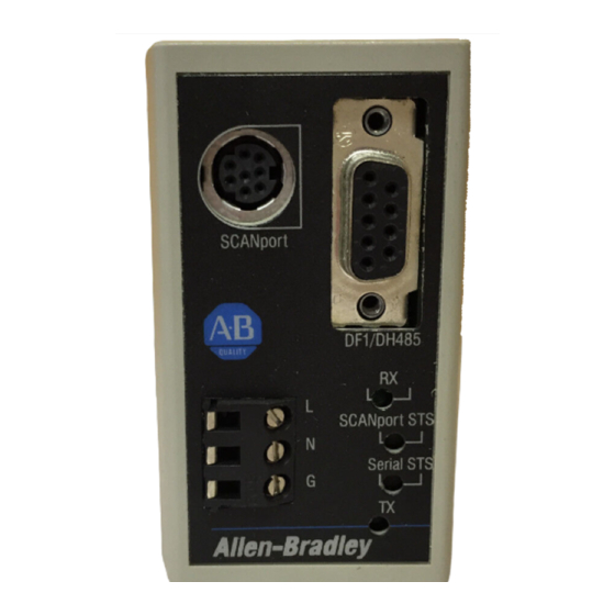
- Page 12 1–4 Product Description Figure 1.2 Enclosed Style Serial-to-SCANport Communications Module SCANport connector Serial channel D-shell connector Power connection SCANport Status Diagnostic 1. LED off: adapter power removed LEDs 2. LED flashing green: link OK, not connected 3. LED solid green: link OK, connected 4.
- Page 13 Product Description 1–5 Figure 1.3 Typical Serial Communications/SCANport Device Interconnect Open Style Comm Module 1336 PLUS Serial port 1305 Micro Drive SCANport Serial communications link Serial Communications Module SLC 5/03 SLC 5/03 CPU SMP 3 SCANport Serial Communications Module Other serial devices AB0396C 1203–5.5 September 1995...
-
Page 14: Configuration Switches
1–6 Product Description Configuration Switches The Serial Communications Module contains three DIP Switches: SW1, SW2, and SW3 (Figure 1.1 and Figure 1.2). Switches are set ON or OFF as shown in Figure 1.4. For a detailed explanation of switch configuration, refer to Chapter 2. Figure 1.4 Configuration Switches Side view of typical... -
Page 15: Installation
Chapter Installation Chapter Objectives In this chapter, you will learn how to: set the module configuration switches mount the Serial Communications Module connect the cables connect the SCANport link connect the power supply Read this chapter completely before you attempt to install or configure your Serial Communications Module. - Page 16 2–2 Installation Factory Switch Settings The following table shows the switch settings that are set at the factory: Switch Setting Communication Mode SW3–8 Default application timeout disabled SW3–7 SW3–6 Duplicate message detection disabled SW3–5 Datalink D disabled SW3–4 Datalink C disabled SW3–3 Datalink B disabled SW3–2...
-
Page 17: Switch Sw1
Installation 2–3 Switch SW1 Switch SW1 is used to select: serial communications mode (RS–232/RS–422/RS–485/DH–485) Serial Communications Module address Communications Protocol Module Address Selection AB0398B Use SW1–1 and SW1–2 to select the communications protocol you are using: Switch Value Protocol (Decimal) RS–232 (DF1 protocol) –... -
Page 18: Df1/Dh-485 Address Selection
2–4 Installation Use SW1–3, SW1–4, SW1–5, SW1–6, SW1–7, and SW1–8 to set your address for the Serial Communications Module. The following table provides the switch settings for selecting the serial device addressing. " Note: If you are using the DH–485 communications mode, the highest serial device address you can select is 31 (decimal). -
Page 19: Df1 Address Selection
Installation 2–5 DF1 Address Selection Module Module Module Module Address Address Address Address (Decimal) (Octal) (Decimal) (Octal) – – 8 7 6 5 4 3 2 1 8 7 6 5 4 3 2 1 – – 8 7 6 5 4 3 2 1 8 7 6 5 4 3 2 1 –... -
Page 20: Switch Sw2
2–6 Installation Switch SW2 Switch SW2 is used to select: baud rate parity number of stop bits point–to–point or multi–drop checksum mode (CRC or BCC) Parity Baud rate setting selection Stop bits Point-to-point/multi-drop Checksum mode AB0399A Use SW2–3, SW2–2, and SW2–1 to select the baud rate: Switch Value Baud Rate (Decimal) - Page 21 Installation 2–7 " Note: If you are using the DH–485 communications mode, setting switches SW2–4, SW2–5, SW2–6. SW2–7, and SW2–8 have no effect because this information is selected within the software. Use SW2–5 and SW2–4 to set the parity: Function Parity disabled –...
-
Page 22: Switch Sw3
2–8 Installation Switch SW3 Switch SW3 is used to select: logic command/status and reference/feedback datalinks (up to four datalinks) duplicate message detection application timeout default value Datalink message Application timeout default values enables Logic command/ Duplicate message status and reference/ detection feedback AB0400B... - Page 23 Installation 2–9 Use SW3–4 to enable and disable Datalink C messaging: Function Disable Datalink C messaging. – 8 7 6 5 4 3 2 1 Enable Datalink C messaging. – 8 7 6 5 4 3 2 1 Use SW3–5 to enable and disable Datalink D messaging: Function Disable Datalink D messaging.
-
Page 24: Mounting The Serial Communications Module
2–10 Installation Mounting the Serial The Serial Communications Module can be provided in three Communications Module mounting configurations: Open style board, factory installed in a drive (not available for all drives) Open style board as a separate kit Enclosed style for panel mount or DIN rail mount This section provides mounting information for the Open style kit and the Enclosed style. - Page 25 Installation 2–11 Enclosed Style Communications Module Mounting Location (1336 FORCE and 1336 PLUS Drives) 1336 FORCE Port Expander SCANport 2 Optional Male–Male Cable Communications Module Communications Module 1203–5.5 September 1995...
-
Page 26: Enclosed Style Serial Communications Module Dimensions
2–12 Installation Enclosed Style Serial Enclosed Style Serial Communications Module Dimensions Communications Module Dimensions 44mm Notes: (1.75) DIN Rail DIN Rail – The enclosure requires clearance at the top and bottom for proper cooling. Additional space is required if you want to access the DIP switches without removing the device. -
Page 27: Connecting Cables
Installation 2–13 Connecting Cables This section provides information that you need to connect the cables to your Serial Communications Module. Important: When connecting your cables, you should make sure that the network is properly terminated. You should also ground the shield at the end furthest from the Serial Communications Module. -
Page 28: Ibm Pc Compatible Serial Connections
2–14 Installation IBM PC Compatible Serial Connections RS–485/RS–422/RS–232 Communications Adapter to IBM AT Compatible Computer RS–232 Serial Port Connection Diagram IBM AT Compatible Communications Module Personal Computer Computer Internal 9-Pin D-Shell RS232 Serial Port Jumper Connectors N.C. N.C. N.C. N.C. N.C. -
Page 29: Plc5 Channel 0 Serial Connections
Installation 2–15 PLC5 Channel 0 Serial Connections Serial Communications Module to PLC5 RS–232 Serial Port Connection Diagram PLC5/20, 5/40, 5/60, 5/80 Channel 0 Communications Module C.GND 9-Pin D-Shell N.C. N.C. N.C. N.C. N.C. N.C. N.C. N.C. SG.GND N.C. N.C. N.C. N.C. -
Page 30: Scanport Link Connection
Expander from the cable length used to connect the device to the expander (B1 + C = a maximum of ten meters). 1305 Drive An Allen-Bradley SCANport link cable is used to connect the Serial Communications Module to the drive (as shown below). SCANport Connection on Serial Communications Module... -
Page 31: 1336 Plus And 1336 Force
1394 Refer to the product manual for connection information. SMP 3 An Allen-Bradley SCANport cable is used to connect the Serial Communications Module to an SMP3. Important: The maximum cable distance between any two devices cannot exceed 10 meters (33 feet) of cable. -
Page 32: Power Supply Connections
2–18 Installation Power Supply The Enclosed Communications Module is powered from a separate Connections 24V DC or 115/230V AC power supply (as shown below). With the Open Style Communications Module board mounted in the drive, no separate power supply connections are required. Typical Power Supply Connection 115/230V Typical... -
Page 33: Scanport Datalink Operation
Chapter SCANport Datalink Operation Chapter Objectives In this chapter, you will read about SCANport Datalinks. SCANport Datalinks A Datalink is a type of pointer function used by some SCANport devices to transfer parameter values to and from the SCANport device. The Datalink function transfers parameters on a regular schedule. - Page 34 3–2 SCANport Data Link Operation 1203–5.5 September 1995...
-
Page 35: Configuring And Interfacing
Chapter Configuring and Interfacing Chapter Objectives This chapter provides you with information on how the Serial Communications Module communicates with a serial device. The following topics are explained: Serial Communications Module data table structure configuration examples ATTENTION: When you configure a system for the first time, you should disconnect the motor from the machine or the process during the initial testing. - Page 36 4–2 Configuring and Interfacing Supported PCCC Command List The Serial Communications Module supports the following PCCC Commands: CMD Code FNC Code Command Name PLC Addressing Method Unprotected read PLC–2 address Echo Read diagnostic counters Variable (modified PLC–2 addresses) Set variables (#ENQs, #NAKs, TIMEOUT) Identify host and some status Set timeout Set #NAKs...
- Page 37 Configuring and Interfacing 4–3 Data Table Structure The Serial Communications Module provides the following data table structures for DF1 and DH–485. The following table is the drive control table (binary file). File File Description Description Address Address B3:0 Logic Command B3:10 Logic Status B3:1...
- Page 38 4–4 Configuring and Interfacing Important: The following two tables list the typical control and status structure. You should refer to your drive manual for the actual control and status structures for your device. The following are the bit definitions for B3:0 or writes to N41:0: Description Description Stop...
- Page 39 Configuring and Interfacing 4–5 The following is the data table structure for PLC–2 style addressing: Parameter PLC–2 Style Address Description of Location’s Purpose Number Decimal (Octal) 512 + Parm # 1 – 7039 Parameter value read (1000 to 16577) (16600 to 167770 Status of last parameter write 7680 + Parm # 1 –...
- Page 40 4–6 Configuring and Interfacing The following is the data table structure for the Serial Communications Module: Parameter Number File Addresses Description of Location’s Purpose 1 – 999 N10:1 – 999 1000 – 1999 N11:0 – 999 Parameter – – value 8000 –...
- Page 41 Configuring and Interfacing 4–7 The data tables have up to eight areas, each having a different purpose. 1. Parameter Value Read or Write (N10 – N19, N50 – N89). Reading data from files in this area will cause the Serial Communications Module to read parameter values from the SCANport device and send those values as the response to the read message.
- Page 42 4–8 Configuring and Interfacing – Datalink A1. Writing to Datalink A1 sends a value to the parameter pointed to by the DataIn A1 parameter of the SCANport device. Reading from Datalink A1 reads the value of the parameter pointed to by the DataOut A1 parameter of the SCANport device.
- Page 43 Configuring and Interfacing 4–9 Configuration Examples DF1 Messaging with a PLC–5/80 Example This example reads parameters 1 through 50. Ladder rung example for Gx2 manual Rung 2:0 | I:000 MG20:0 +MSG––––––––––––––––––––+ +––] [–––]/[–––[ONS]––––––––––––––––––––––––––––+SEND/RECEIVE MESSAGE +–(EN)–+ |Control block MG20:0+–(DN) | +–(ER) | +–––––––––––––––––––––––+ Data Table Report MESSAGE INSTRUCTION DATA MONITOR FOR CONTROL BLOCK MG20:0...
- Page 44 4–10 Configuring and Interfacing Notes: I:000/00 is any application–related conditioning logic. MG20:0.EN is the enabled status bit from the message block. B3/2 is a one-shot that causes the message to be resent each time the message block completes or errors (as long as I:000/00 is true).
- Page 45 Configuring and Interfacing 4–11 DF1 Messaging with a 1746–BAS Module Example This example accepts a parameter number and a value from a user terminal and writes the data out to a SCANport–compatible device. REM _____________________________________________________________ REM __ This program inputs a parameter number and a value rem __ from a user terminal and writes it out to a scanport rem __ compatible device.
- Page 46 4–12 Configuring and Interfacing REM **************************************************************** REM ********* PLC TYPED READ Subroutine ***** REM ********* inputs Parameter number in var PAR_NUM ***** REM ********* ASC coded hex string of value in $(1) ***** REM ********* outputs: failure message ***** REM **************************************************************** REM subroutine to do a typed write of a single parameter PRINT ”Executing PLC Remote Write ”...
- Page 47 Configuring and Interfacing 4–13 DH–485 Messaging with a SLC5/03 Interface The following example uses the DH–485 communications mode to send a message from an SLC5/03 to the Serial Communications Module. Rung 2:0 If this is the first scan or the error bit is true, the MSG instruction’s control byte is cleared and the done bit is set.
- Page 48 4–14 Configuring and Interfacing Rung 2:2 When the timer is done, the MSG instruction is enabled. | TON Done – | Enable | MSG Block T4:0 +MSG––––––––––––––––––––+ |––––] [––––––––––––––––––––––––––––––––––––––––+READ/WRITE MESSAGE +–(EN)–| |Type PEER–TO–PEER+–(DN) | |Read/Write WRITE+–(ER) | |Target Device 500CPU| |Local/Remote LOCAL| |Control Block...
-
Page 49: Block Transfer Emulation Instructions
Chapter Block Transfer Emulation Instructions Chapter Objectives This chapter contains the header and data configurations that you need to set up the data files for the block transfer emulation instructions. The header and data values depend on the operation you want to perform. Block Transfer Emulation When an operation is unsuccessful, header word 2 of the drive Status Word... - Page 50 5–2 Scattered Parameter Value The Scattered Parameter Value Read function reads a scattered list of Read parameters. PLC Block Transfer Emulation Instruction Data PLC request instruction length: 5–63 words Drive response instruction length: 5–63 words Message Structure PLC Request Drive Response Message Length Header Word 1 5–63...
- Page 51 Block Transfer Emulation Instructions 5–3 Message Operation Scattered Parameter Value Read reads a pre–defined group of parameter values, in any order, from the device. You define the number of parameters to read in word 3 of the request. The parameters to be read and their order is defined starting with word 4. An unused word is left between each parameter request, so the drive can respond with the parameter value, as shown.
- Page 52 5–4 Scattered Parameter Value The Scattered Parameter Value Write function writes to a scattered Write list of parameters and returns the status of each parameter. If any of the states have errors, the parameter number is negative. PLC Block Transfer Emulation Instruction Data PLC request instruction length: 5–63 words Drive response instruction length: 5–63 words Message Structure...
- Page 53 Block Transfer Emulation Instructions 5–5 Message Operation The Scattered Parameter Value Write function writes data values to a pre–defined group of device parameters in any order. You define the number of parameters to write in word 3. The parameters to be written to and their order is defined starting with word 4.
- Page 54 5–6 Product ID Number Read The Product ID Number Read function returns the product ID of the device to which the Serial Communications Module is connected. PLC Block Transfer Emulation Instruction Data PLC request instruction length: 3 words Drive response instruction length: 4 words Message Structure PLC Request Drive Response...
- Page 55 Block Transfer Emulation Instructions 5–7 Example In this example, the Product ID Number Read was requested. The drive response contained a value of 3 in word 4 of its message response, indicating a connection to a 1336 PLUS. Data File Format PLC request N10:0 Drive response...
- Page 56 5–8 Parameter Read Full The Parameter Read Full function provides all known attributes for the parameters requested. This information includes the parameter’s current value, descriptor, multiply and divide value, base value, offset value, text string, group element reference, minimum value, maximum value, default value, and unit text string.
- Page 57 Block Transfer Emulation Instructions 5–9 Message Structure (Continued) Drive Response Data File, Group, Element Word 15 Data Minimum Value Word 16 Data Maximum Value Word 17 Data Default Value Word 18 Unit Text Data Word 19 Char 2 Char 1 Unit Text Data Word 20...
- Page 58 5–10 This example shows the response message N10:90 through N10:112 in both binary and ASCII. Note the ASCII information beginning with N10:99. The parameter name characters return in reverse order for each word. N10:99 has the ASCII value of (aM). To read this, invert the word to read (Ma).
- Page 59 Block Transfer Emulation Instructions 5–11 Parameter Value Read The Parameter Value Read function reads the 16–bit parameter data value for the selected parameter number. PLC Block Transfer Emulation Instruction Data PLC request instruction length: 3 words Drive response instruction length: 1 word Message Structure PLC Request Drive Response...
- Page 60 5–12 Parameter Value Write The Parameter Value Write message writes a 16–bit parameter data value to the selected parameter number. PLC Block Transfer Emulation Instruction Data PLC request instruction length: 1 word Drive response instruction length: 4 words Message Structure PLC Request Drive Response Parameter Value...
- Page 61 Block Transfer Emulation Instructions 5–13 EE Memory Functions The EE Memory Functions message activates the specified EE functions. PLC Block Transfer Emulation Instruction Data PLC request instruction length: 4 words Drive response instruction length: 3 words Message Structure PLC Request Drive Response Message Length Header Word 1...
- Page 62 5–14 Example This example requests that an EEPROM Save function be performed. Data File Format PLC request N10:10 –31998 N10:90 Drive response * Example only – These values vary depending on parameters and products. 1203–5.5 September 1995...
- Page 63 Block Transfer Emulation Instructions 5–15 Fault Clear/Reset The Fault Clear/Reset message activates the Clear Fault, Clear Fault Queue, and Drive Reset functions. PLC Block Transfer Emulation Instruction Data PLC request instruction length: 4 words Drive response instruction length: 4 words Message Structure PLC Request Drive Response...
- Page 64 5–16 Fault Queue Entry Read This function reads the contents of the specified fault queue entry. A Full message is returned which includes the fault text and fault code associated with the specified fault queue entry. The 1336 FORCE also returns the time stamp associated with the fault. PLC Block Transfer Emulation Instruction Data PLC request instruction length: 3 words Drive response instruction length: 12 or 16 words...
- Page 65 Block Transfer Emulation Instructions 5–17 Message Operation Fault Queue Entry Read Full reads the contents of the fault queue specified in word 3 of the request. The response returns the fault text which can be ASCII text. The text will have every two characters in reverse order.
- Page 66 5–18 Fault Queue Size The Fault Queue Size function gets the number of fault entries allowed in the fault queue. PLC Block Transfer Emulation Instruction Data PLC request instruction length: 3 words Drive response instruction length: 4 words Message Structure PLC Request Drive Response Message Length...
- Page 67 Block Transfer Emulation Instructions 5–19 Trip Fault Queue Number The Trip Fault Queue Number provides the fault queue number of the fault that caused the device to trip. PLC Block Transfer Emulation Instruction Data PLC request instruction length: 3 words Drive response instruction length: 4 words Message Structure PLC Request...
- Page 68 5–20 1203–5.5 September 1995...
-
Page 69: Troubleshooting
Communications Module system using the LED indicators on the front of the device (as shown below). The Serial Communications Module is a non-serviceable device that you should return to Allen-Bradley for replacement when a major fault exists that is attributable to the Serial Communications Module itself. LED Locations... - Page 70 6–2 Troubleshooting ATTENTION: Servicing energized industrial control equipment can be hazardous. Electrical shock, burns, or unintentional actuation of controlled industrial equipment may cause death or serious injury. Follow the safety-related practices of NFPA 70E, Electrical Safety for Employee Workplaces, when working on or near energized equipment.
-
Page 71: Specifications
This module is intended for use with devices that communicate via RS–232, RS–422, or RS–485 hardware standards using the DF1 protocol or the DH–485 standard. The Serial Communications Module is intended to provide a means for transmitting messages between these serial communications devices and Allen-Bradley SCANport devices. 1203–5.5 September 1995... - Page 72 7–2 Specifications 1203–5.5 September 1995...
- Page 73 Philippines Poland Portugal Puerto Rico Qatar Romania Russia–CIS Saudi Arabia Singapore Slovakia Slovenia South Africa, Republic Spain Sweden Switzerland Taiwan Thailand Turkey United Arab Emirates United Kingdom United States Uruguay Venezuela Yugoslavia Allen-Bradley Headquarters, 1201 South Second Street, Milwaukee, WI 53204 USA, Tel: (1) 414 382-2000 Fax: (1) 414 382-4444 1203–5.5 September 1995 Template revised June 23, 1203–5.5 September 1995...