Table of Contents
Table of Contents

Related Manuals for Allen-Bradley ControlLogix 1756-ENBT


Summary of Contents for Allen-Bradley ControlLogix 1756-ENBT
- Page 1 ControlLogix Ethernet Bridge Module 1756-ENBT User Manual AB Parts...
- Page 2 In no event will Allen-Bradley be responsible or liable for indirect or consequential damage resulting from the use or application of these products.
- Page 3 Rockwell Automation Before you contact Rockwell Automation for technical assistance, we suggest you please review the troubleshooting information contained Support in this publication first. If the problem persists, call your local Rockwell Automation representative or contact Rockwell Automation in one of the following ways: Phone United...
- Page 5 Preface About This User Manual What this Preface Contains This preface describes how to use this manual. The following table describes what this preface contains and where to find specific information. For information about See page Who Should Use This Manual Common Techniques Used in This Manual How To Use This Manual About the Example Applications...
- Page 6 About This User Manual Common Techniques The following conventions are used throughout this manual: Used in This Manual • Bulleted lists provide information, not procedural steps. • Numbered lists provide sequential steps. • Information in bold contained within text identifies menu windows, or screen options, screen names and areas of the screen, such as dialog boxes, status bars, radio buttons and parameters.
- Page 7 About This User Manual About the Example Applications The example applications presented in this manual are as follows: • Using Rack Optimized I/O (chapter 5) • Using Analog I/O with Direct Connection (chapter 6) • Using Produced and Consumed tags (chapter 7) •...
- Page 8 About This User Manual System Components We used the following components for the example applications: Quantity Product Name Catalog Number Hardware ControlLogix Chassis 1756-A4, (or -A7, -A13, -A13, -A17) ControlLogix Power Supply 1756-PA72, (or -PB72) ControlLogix EtherNet/IP Bridge Module 1756-ENBT Logix5550 Controller 1756-L1 ControlLogix Analog Output Module...
- Page 9 About This User Manual Where to Find More Refer to the following Rockwell publications as needed for additional help when setting up and using your network. Information For information about See this publication Publication number Using Ethernet for industrial control EtherNet/IP Performance and Application Guide ENET-AP001 EtherNet/IP media...
- Page 10 About This User Manual Notes: Publication 1756-UM050A-EN-P - December 2001...
-
Page 11: Table Of Contents
Table of Contents Chapter 1 About the 1756-ENBT Module What This Chapter Contains ......1-1 Module Features. - Page 12 Table of Contents Using RSLinx Software ......4-7 Using a Third Party BootP Server ..... 4-10 Using DHCP Software to Configure Your Module .
- Page 13 Table of Contents Create the Consumer Tags......7-15 Download the Configuration to the Consumer ..7-18 Test the Messaging .
- Page 14 Table of Contents Appendix E Autonegotiation Requirements Manual Configuration on an Ethernet Switch ....E-1 Changing Ports on an Ethernet Switch....E-1 Index Publication 1756-UM050A-EN-P - December 2001...
-
Page 15: What This Chapter Contains
About the 1756-ENBT Module What This Chapter Contains This chapter provides an overview of the ControlLogix 1756-ENBT module, its primary features, what it does, and how to use it. You will need to understand the concepts discussed in this chapter to configure your EtherNet/IP Bridge module and use it in a control system. -
Page 16: Hardware/Software Compatibility
About the 1756-ENBT Module Hardware/Software The 1756-ENBT module is compatible with the following product’s firmware versions and software releases. Contact Rockwell Compatibility Automation if you need software or firmware upgrades to use this equipment.: Product Firmware Version/ Software Release 1756-ENBT module 1.x or higher 1756-ENET/A/B 1.18 or higher... -
Page 17: Mixing Rack Optimized And Direct Connections
About the 1756-ENBT Module Rack optimized connections reduce the total number of connections needed to transfer data when using many I/O modules in a system. The following example illustrates the benefit of rack optimized connections. Assume you have set up a system that contains 10 discrete I/O modules in a remote ControlLogix chassis. -
Page 18: Use Of The Control And Information Protocol (Cip)
About the 1756-ENBT Module Use of the Control and The 1756-ENBT module uses the Control and Information Protocol (CIP). CIP is the application layer protocol specified for EtherNet/IP, Information Protocol (CIP) the Ethernet Industrial Protocol, as well as for ControlNet and DeviceNet. -
Page 19: Specifying The Requested Packet Interval (Rpi)
About the 1756-ENBT Module You configure the producer and consumer by creating controller scoped tags using RSLogix 5000 software (see chapter 7). Tag Type Description Specify Using RSLogix5000 Software Tags that the controller produced for other Enabled for producing Produced nodes to consume. - Page 20 About the 1756-ENBT Module Publication 1756-UM050A-EN-P - December 2001...
-
Page 21: What This Chapter Contains
Chapter Installing the 1756-ENBT Module What This Chapter Contains This chapter describes how to physically install the module in the ControlLogix chassis and connect it to the network. The following table describes what this chapter contains and where to find specific information. -
Page 22: Identifying Module Components
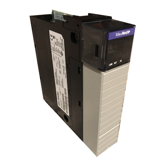
Installing the 1756-ENBT Module Identifying Module Use the following figure to identify the external features of the 1756-ENBT module. Components Backplane Front View Side View Connector Front Panel LINK NET OK MAC ID Label (Inside) Backplane Ethernet connector Connector located on underside Bottom View of module Front... -
Page 23: Determining Module Slot Location
Installing the 1756-ENBT Module For information on installing these products, refer to the publications listed in the following table. Chassis Chassis Power Power Supply Type Installation Supply Installation Series B: 1756-A4, -A7, -A10, -A13 Pub. No. 1756-PA72/B Pub. No. 1756-IN080 1756-5.67 1756-PB72/B 1756-PA75/A... -
Page 24: Installing The Module In The Chassis
Installing the 1756-ENBT Module Installing the Module in the Chassis Align the circuit board with top and bottom guides in the chassis. Circuit Board 31275-M Slide the module into the chassis. Make sure the module backplane connector properly connects to the chassis backplane. -
Page 25: Removing Or Replacing The Module (When Applicable)
Installing the 1756-ENBT Module Removing or Replacing the Module (when applicable) Push on upper and lower module tabs to disengage them. 31277-M Slide module out of chassis. 31278-M If you are replacing an existing module with an IMPORTANT identical one, and you want to resume identical system operation, you must install the new module in the same slot. -
Page 26: Installing Or Removing The Module Under Power
Installing the 1756-ENBT Module Installing or Removing the This module is designed to be installed or removed while chassis power is applied. Module Under Power When you insert or remove a module while WARNING backplane power is on, an electrical arc may occur. An electrical arc can cause personal injury or property damage by: •... -
Page 27: Connecting The Module To The Network
Installing the 1756-ENBT Module Connecting the Module to If you connect or disconnect the Ethernet cable with the Network WARNING power applied to this module or any device on the network, an electrical arc can occur. This could cause an explosion in hazardous location installations. -
Page 28: Applying Chassis Power
Installing the 1756-ENBT Module Applying Chassis Power 31280-M Checking Power Supply Check the LED indicators and alphanumeric display to determine if the power supply and module are operating properly. and Module Status Alphanumeric Display LINK NET OK OK indicator is LINK red during self-test, then green. -
Page 29: What This Chapter Contains
Chapter Before You Configure Your Module What This Chapter Contains This chapter describes some of the basics you should know about Ethernet before you configure your 1756-ENBT module. The following table describes where to find specific information in this chapter. For information about See page Ethernet Protocols... -
Page 30: User Datagram Protocol (Udp)
Before You Configure Your Module User Datagram Protocol (UDP) UDP is a much simpler transport protocol. It is connectionless and provides a very simple capability to send datagrams between two devices. UDP is used by applications that implement their own handshaking between devices and only want a minimal transport service. -
Page 31: Configuration Requirements
Before You Configure Your Module Configuration Before you can use your 1756-ENBT module, you must configure its IP address, gateway address, and subnet mask. The module ships with Requirements the Rockwell BootP utility, which you can use to perform the configuration. -
Page 32: Gateways
Before You Configure Your Module Contact your network administrator or the Network Information Center for a unique fixed IP address to assign to your module. For more information on Internet addressing, see Comer, Douglas E; Internetworking with TCP-IP, Volume 1: Protocols and Architecture; Englewood Cliffs, N.J.: Prentice-Hall, 1990. -
Page 33: Subnet Mask
Before You Configure Your Module Subnet Mask Subnet addressing is an extension of the IP address scheme that allows a site to use a single net ID for multiple physical networks. Routing outside of the site continues by dividing the IP address into a net ID and a host ID via the class. -
Page 34: For More Information
Before You Configure Your Module For More Information For more information about Ethernet, refer to the following publications: • Internetworking with TCP/IP ISBN 0-13-216987-8 Vol. 1, 2nd ed. by Douglas E. Comer • The Ethernet Management Guide – ISBN 0-07-046320-4 Keeping The Link •... -
Page 35: What This Chapter Contains
Chapter Configuring the 1756-ENBT Module What This Chapter Contains Before you can use your 1756-ENBT module in a network you must configure it by providing an IP address, Gateway address, and Subnet mask. There are several way you can do this: 1. -
Page 36: Using The Rockwell Bootp Utility
Configuring the 1756-ENBT Module Using the Rockwell The Rockwell BootP utility is a stand alone program that incorporates the functionality of standard BootP software with a user friendly BootP Utility graphical interface. It is located in the Utils directory on the RSLogix 5000 installation CD. - Page 37 Configuring the 1756-ENBT Module The device will be added to the Relation List, displaying the Ethernet Address (MAC) and corresponding IP Address, Subnet Mask, and Gateway (if applicable). 4. If you want to permanently assign this configuration to the device, highlight the device and click on the Disable BOOTP button.
-
Page 38: Using Force Ip Renew To Reconfigure A Device
Configuring the 1756-ENBT Module Using Force IP Renew To Reconfigure a Device The Force IP Renew feature can be used to reconfigure a device that has Bootp disabled. This can be useful: • if you do not know the IP address of a configured device (e.g., the address is not written on the label or the label is missing), or •... - Page 39 Configuring the 1756-ENBT Module 4. Enter the IP Address, Subnet Mask, and Gateway you want to assign to the device, and click on OK. The device will appear in the Relation List. 5. Select the device from the Relation List and click on the Force IP Renew button.
-
Page 40: Saving The Relation List
Configuring the 1756-ENBT Module Saving the Relation List You can save the Relation List to be used later. To save the Relation List perform the following steps: 1. Select Save As... from the File menu. You will see the following window. -
Page 41: Using Rslinx Software
Configuring the 1756-ENBT Module You can then open the file containing the Relation List at a later session. Using RSLinx Software You can use RSLinx software, version 2.2 or higher, to configure the 1756-ENBT module via a ControlNet or Data Highway Plus network, or via the serial port on a Logix 5550 processor, if you insert the 1756-ENBT module into a ControlLogix chassis containing: •... - Page 42 Configuring the 1756-ENBT Module The RSWho window will open. 3. Select the appropriate driver (e.g., AB_KT-1 for Data Highway Plus, AB_KTC-1 for ControlNet, or AB_DF1-1 for the Logix 5550’s serial port). The following example uses the AB_DF1-1 driver. You can perform the same steps using one of the other drivers.
- Page 43 Configuring the 1756-ENBT Module The following pop-up menu will appear. 5. Select Module Configuration, then select the Port Configuration tab. 6. Uncheck the Obtain IP Address from BootP Server box. 7. Enter the desired IP Address, Subnet Mask, and optional Gateway Address.
-
Page 44: Using A Third Party Bootp Server
4-10 Configuring the 1756-ENBT Module Using a Third Party The 1756-ENBT module factory default is BootP enabled. The following is an example BootP tab file that can be used with a third BootP Server party BootP server: # Example /etc./bootptab: database for bootp server (/etc./bootpd). EXAMPLE # Format: nodename:tag=value:tag=value: . - Page 45 Configuring the 1756-ENBT Module 4-11 zappa2:\ tc=icp.defaults:\ ha=0000bc034022:\ ip=130.151.132.123 To use a BootP server to configure the 1756-ENBT module perform the following steps: 1. Access and open the BootP tab file using a text editor. 2. Enter the IP address of your module. If you need more information on setting IP addresses, refer to pages 3-3 to 3-4.
-
Page 46: Using Dhcp Software To Configure Your Module
4-12 Configuring the 1756-ENBT Module Using DHCP Software to DHCP (Dynamic Host Configuration Protocol) software automatically assigns IP addresses to client stations logging onto a TCP/IP network. Configure Your Module DHCP is based on BootP and maintains some backward compatibility. The main difference is that BootP was designed for manual configuration, while DHCP allows for dynamic allocation of network addresses and configurations to newly attached devices. -
Page 47: Using Rack Optimized I/O
Chapter Using Rack Optimized I/O About the Example This example uses rack optimized connections to read data from a remote digital input module and send data to a remote digital output Application module. What you will do See page Set Up the Hardware Create the Example Application Add the Local Ethernet Bridge to the I/O Configuration Add the Remote Ethernet Bridge to the I/O Configuration... -
Page 48: Set Up The Hardware
Using Rack Optimized I/O Set Up the Hardware For this example, one ControlLogix chassis contains a Logix 5550 controller in slot 0 and a 1756-ENBT module in slot 1. A second chassis contains a 1756-ENBT module in slot 0 and the I/O modules in slots 1 and 2. -
Page 49: Create The Example Application
Using Rack Optimized I/O Create the Example Perform the following steps to create the example application: Application 1. Start RSLogix5000. The RSLogix 5000 Main Window will open. 2. From the File menu, select New. The New Controller pop-up window will open. 3. -
Page 50: Add The Local Ethernet Bridge To The I/O Configuration
Using Rack Optimized I/O You now add the remote digital I/O modules to the controller’s I/O configuration. To do this you first add the local 1756-ENBT module to the I/O configuration. Next you add the 1756-ENBT in the remote chassis with the digital I/O modules as a “child” of the local 1756-ENBT module. - Page 51 Using Rack Optimized I/O The Select Module Type window will open. 3. Select the 1756-ENBT/A Ethernet Bridge and click on OK. The Module Properties window will open. 4. Enter or select the following parameters: Name, IP Address, Slot, and Electronic Keying. We used the following values: Name Local_ENB IP Address...
-
Page 52: Add The Remote Ethernet Bridge To The I/O Configuration
Using Rack Optimized I/O Add the Remote Ethernet Bridge to the I/O Configuration Next, you must add the remote 1756-ENBT module as a “child” of the local 1756-ENBT module. 1. In the Project window, right click on the local 1756-ENBT module under the I/O Configuration folder and select New Module from the pop-up window. - Page 53 Using Rack Optimized I/O The Module Properties window will open. 3. Enter or select the following parameters (the values we used are listed in the table): Name Remote_ENB IP Address 130.130.130.3 Chassis Size Slot Comm Format Rack Optimization Electronic Keying Compatible Module 4.
-
Page 54: Add The Remote I/O Modules To The I/O Configuration
Using Rack Optimized I/O 6. Click on the Finish button to accept the configuration. The remote 1756-ENBT module will appear indented under the local 1756-ENBT in the I/O Configuration folder. Add the Remote I/O Modules to the I/O Configuration You must now add the remote I/O modules to the I/O Configuration List under the remote 1756-ENBT module. - Page 55 Using Rack Optimized I/O 2. The Select Module Type window will open. 3. Select the 1756-IB16I digital input module from the list and click on OK. The Module Properties window will open. 4. Enter the following parameters (the values we used are listed in the table): Name Remote_Digital_Input...
-
Page 56: Add The Remote Digital Output Module
5-10 Using Rack Optimized I/O If you want to alter the default parameters, click on the Next button. Refer to the ControlLogix Digital I/O User Manual, publication 1756-6.5.8, for details. 5. Click on the Finish button to save the configuration. The digital input module will appear in the I/O configuration indented under the remote 1756-ENBT module. - Page 57 Using Rack Optimized I/O 5-11 The Select Module Type window will open. 7. Select the 1756-OB16I digital output module from the list and click on OK. The Module Properties window will open. 8. Enter the following parameters (the values we used are listed in the table): Name Remote_Digital_Output...
-
Page 58: Edit The Controller Tags
5-12 Using Rack Optimized I/O 9. Click on the Finish button to accept the configuration. The I/O Configuration in the Project window should look similar to the one shown below. Edit the Controller Tags When you add modules to the I/O configuration the system creates tags for those modules to use in the application program. - Page 59 Using Rack Optimized I/O 5-13 3. Create the following tag: Type Parts_Count Counter AB Parts Publication 1756-UM050A-EN-P - December 2001...
-
Page 60: Create The Ladder Program
5-14 Using Rack Optimized I/O Create the Ladder Program To create a ladder program to test the configuration perform the following steps: 1. Double-click on Main Routine under the Main Program folder, and enter the following ladder program, using the tags previously created. -
Page 61: Download The Program To The Controller
Using Rack Optimized I/O 5-15 Download the Program to the Controller 1. Click on the Communications menu and select Who Active. The Who Active window will open (Your window will show the drivers and devices you have installed). 2. Select your Ethernet driver (e.g., AB_ETH-1) and expand the tree through the backplane of the local ControlLogix chassis. -
Page 62: Test The Example Application
5-16 Using Rack Optimized I/O Test the Example You will test the example application by using a momentary switch to simulate a parts sensor. Application 1. Wire the 1756-IB16I digital input module as shown in the following figure: 1756-IB16I IN-0 GND-0 Count Reset... -
Page 63: What's Next
Using Rack Optimized I/O 5-17 Refer to the ControlLogix Digital I/O Modules User Manual, publication 1756-6.5.8, for assistance in wiring and debugging the I/O modules. This completes the Rack Optimized I/O example. What’s Next? The following chapter describes an example application in which you add an analog output module to the I/O configuration using a direct connection. - Page 64 5-18 Using Rack Optimized I/O Publication 1756-UM050A-EN-P - December 2001...
-
Page 65: Using Analog I/O With Direct Connection
Chapter Using Analog I/O with Direct Connection About the Example In this example you add an analog output module to the remote chassis containing the 1756-ENBT module and the two digital I/O Application modules configured in the previous chapter. Analog modules default to direct connection. -
Page 66: Set Up The Hardware
Using Analog I/O with Direct Connection Set Up the Hardware Change the system configuration of the previous chapter to that shown below, adding an analog output module to the remote chassis in slot 3. For this example, we used a 1756-OF8 analog output module. -
Page 67: Create The Example Application
Using Analog I/O with Direct Connection Create the Example Perform the following steps to create the example application: Application 1. Start RSLogix5000. The RSLogix 5000 Main Window will open. Open 2. Open the project file from the previous chapter (i.e., “Ethernet_IO_Controller”). -
Page 68: Add The Remote Analog I/O Module To The I/O Configuration
Using Analog I/O with Direct Connection Add the Remote Analog I/O Module to the I/O Configuration You must now add the new remote analog I/O module to the I/O Configuration. In this example, you add the 1756-OF8 analog output module and configure one of its channels for a 0V to 10V output range. - Page 69 Using Analog I/O with Direct Connection The Module Properties window will open. 3. Enter the following parameters: Name Remote_Analog_Output Slot Comm Format Float Data Electronic Keying Compatible Module All analog Comm Formats use direct connection. The default is floating decimal point data. You must now configure the channel settings of the Analog I/O module.
- Page 70 Using Analog I/O with Direct Connection 6. Click on Next to open the next page. This page is used during online monitoring but not during initial configuration. 7. Click on Next to move to the first channel configuration page. The choices available on the channel configuration pages vary according to the module being configured.
- Page 71 Using Analog I/O with Direct Connection 9. Click on Next twice to access the Limits page. 10.Enter the following Limits: High Clamp 8000 Low Clamp 11.Click on Finish to save the configuration. The I/O Configuration tree should now look similar to the one shown below.
-
Page 72: Edit The Controller Tags
Using Analog I/O with Direct Connection Edit the Controller Tags When you add modules to the I/O configuration the system creates tags for those modules. We now need to add another Controller Tag to modify the application program. 1. Double-click on the Controller Tags folder in the project window. 2. - Page 73 Using Analog I/O with Direct Connection The tag editor will become active. 4. Create the following tag: Tag Name Type Analog_Output Timer AB Parts Publication 1756-UM050A-EN-P - December 2001...
-
Page 74: Modify The Ladder Program
6-10 Using Analog I/O with Direct Connection Modify the Ladder Program To modify the ladder program to test the new configuration perform the following steps: 1. Double-click on Main Routine under the Main Program folder, and add rungs 3 and 4 to the ladder program of the previous chapter. -
Page 75: Download The Program
Using Analog I/O with Direct Connection 6-11 Download the Program 1. Click on the Communications menu and select Who Active. 2. The Who Active window will open (Your window will display the drivers and devices you have configured on your system). 3. -
Page 76: Test The Example Application
6-12 Using Analog I/O with Direct Connection Test the Example Use the following procedure to test the operation of the remote analog output: Application 1. Connect a voltmeter across the channel 0 output of the 1756-OF8 analog output module as shown in the following figure: 1756-OF8 VOUT-0 –... -
Page 77: Using Produced And Consumed Tags
Chapter Using Produced and Consumed Tags About the Example In this example one Logix5550 controller (the producer) sends data to another Logix5550 controller (the consumer) over the EtherNet/IP Application network. A Timer provides the test data for the message. What you will do See page Set Up the Hardware Create the Producer Application... -
Page 78: Set Up The Hardware
Using Produced and Consumed Tags Set Up the Hardware In both chassis the controller is in slot 0 and the 1756-ENBT module is in slot 1. Slot 0 1 Slot 0 1 2 Data Logix5550 1756-ENBT Logix5550 1756-ENBT (Producer) 130.130.130.2 (Consumer) 130.130.130.3 Switch... -
Page 79: Create The Producer Application
Using Produced and Consumed Tags Create the Producer Perform the following steps to create the producer application. Application 1. Start RSLogix5000. The RSLogix 5000 Main Window will open. 2. From the File menu, select New. The New Controller window will open. 3. -
Page 80: Create The Producer Tags
Using Produced and Consumed Tags Create the Producer Tags 1. Double-click on the Controller Tags folder in the project window. The Controller Tags window will open. Enter the new tags starting here. 2. Select the Edit Tags tab and create the following tags: Tag Name Type Style... - Page 81 Using Produced and Consumed Tags 3. Designate the tag as a produced tag. Either: Check the “P” box in the tag database to make this a produced tag. a. Check the “P” box in the tag database, or b. Right-click on the tag. You will see the following pop-up menu.
-
Page 82: Create The Producer Ladder Program
Using Produced and Consumed Tags Create the Producer Ladder Program Perform the following steps to create a program to produce the test data. 1. Double-click on Main Routine under the Main Program folder, and create the following ladder program, using the tags you previously created. -
Page 83: Download The Producer Application
Using Produced and Consumed Tags Download the Producer Application 1. Click on the Communications menu and select Who Active. The Who Active window will open (Your window will display the drivers and devices you have installed). 2. Select your Ethernet driver (e.g., AB_ETH-1) and expand the tree through the backplane of the local ControlLogix chassis. -
Page 84: Create The Consumer Application
Using Produced and Consumed Tags Create the Consumer In order to test the messaging application you have to create a consumer application, add the producer to the I/O configuration of Application the consumer, and create a consumed tag to receive the data. Create the Consumer Controller Perform the following steps to create the consumer controller: 1. -
Page 85: Add The Producer To The Consumer's I/O Configuration
Using Produced and Consumed Tags Add the Producer to the Consumer’s I/O Configuration Adding the producer to the I/O configuration of the consumer involves several steps. First, you must add the consumer’s local 1756-ENBT module to the I/O configuration. Then you add the remote 1756-ENBT as a “child”... - Page 86 7-10 Using Produced and Consumed Tags The Module Properties window will open. 4. Enter the following parameters: Name Local_ENB Slot Electronic Keying Compatible Module 5. Click on Finish to accept the configuration. The 1756-ENBT module will be added to the I/O configuration. Publication 1756-UM050A-EN-P - December 2001...
-
Page 87: Add The Remote Ethernet Bridge To The I/O Configuration
Using Produced and Consumed Tags 7-11 Add the Remote Ethernet Bridge to the I/O Configuration Next, you must add the remote 1756-ENBT as a “child” of the local 1756-ENBT. 1. In the Project window, right click on the local 1756-ENBT module under the I/O Configuration folder and select New Module from the pop-up window. - Page 88 7-12 Using Produced and Consumed Tags The Module Properties window will open. 3. Enter the following parameters: Name Remote_ENB IP Address 130.130.130.2 Chassis Size Slot Comm Format Rack Optimization Electronic Keying Compatible Module 4. Click on Finish to accept the configuration. The remote 1756-ENBT module will appear indented under the local 1756-ENBT in the I/O Configuration folder.
-
Page 89: Add The Remote (Producer) Controller To The I/O Configuration
Using Produced and Consumed Tags 7-13 Add the Remote (Producer) Controller to the I/O Configuration You must now add the remote Controller (the Producer) to the I/O Configuration under the remote 1756-ENBT module. 1. Right click on the remote 1756-ENBT module under the I/O Configuration folder and select New Module. - Page 90 7-14 Using Produced and Consumed Tags The Module Properties window will open. 3. Enter the following parameters: Name Producer Slot 4. Click on the Finish button to accept the configuration. The I/O Configuration tree should look similar to the one shown below.
-
Page 91: Create The Consumer Tags
Using Produced and Consumed Tags 7-15 Create the Consumer Tags Create a tag for the consumed data by performing the following steps. 1. Double-click on the Controller Tags icon in the Project window. The Controller Tags window will open. You will see the tags created by the system when you added the I/O (e.g., Remote ENB:I, Remote_ENB:O). - Page 92 7-16 Using Produced and Consumed Tags Your tag database should appear similar to that shown below. 3. Right-click on the new tag. The following pop-up menu will open: 4. Select Edit Tag Properties. The Tag Properties window will open. Publication 1756-UM050A-EN-P - December 2001...
- Page 93 Using Produced and Consumed Tags 7-17 5. Enter or select the following parameters: Name consumed_data Tag Type Consumed Producer Producer Remote Tag Name produced_data Data Type DINT Style Decimal 10ms These parameters must match those of the Producer. 6. Click on OK to save the tag properties. AB Parts Publication 1756-UM050A-EN-P - December 2001...
-
Page 94: Download The Configuration To The Consumer
7-18 Using Produced and Consumed Tags Download the Configuration to the Consumer You must now load the configuration parameters to the Consumer controller. Note that no ladder logic is required for routing in the Consumer. The logic can consist of a single “End” rung. 1. -
Page 95: Test The Messaging
Using Produced and Consumed Tags 7-19 Test the Messaging 1. Open the session of RSLogix 5000 for the Producer and verify that the timer is running. 2. In the RSLogix 5000 session for the Consumer controller: a. Double-click on the Controller Tags folder and select the Monitor Tags tab. - Page 96 7-20 Using Produced and Consumed Tags Publication 1756-UM050A-EN-P - December 2001...
-
Page 97: About The Example Application
Chapter Interfacing with FLEX I/O About the Example In this example the ControlLogix processor communicates with FLEX I/O via a 1756-ENBT module and a 1794-AENT FLEX I/O adapter Application using a rack optimized connection. The processor reads data from a digital input module and sends data to a digital output module. -
Page 98: Set Up The Hardware
Interfacing with FLEX I/O Set Up the Hardware In this example, the ControlLogix chassis contains the Logix 5550 processor in slot 0 and a 1756-ENBT bridge module in slot 1. The 1794-AENT adapter is mounted on a DIN rail with a 1794-IB16 digital input module and 1794-OB16 digital output module. -
Page 99: Create The Example Application
Interfacing with FLEX I/O Create the Example Perform the following steps to create the example application: Application 1. Start RSLogix5000. The RSLogix 5000 Main Window will open. 2. From the File menu, select New. The New Controller pop-up window will open. 3. -
Page 100: Configure The I/O
Interfacing with FLEX I/O Configure the I/O You now add the FLEX I/O modules to the controller’s I/O configuration. To do this you first add the local 1756-ENBT module to the I/O configuration. Next you add the 1794-AENT adapter as a “child”... - Page 101 Interfacing with FLEX I/O The Select Module Type window will open. 3. Select the 1756-ENBT EtherNet/IP Bridge and click on OK. The Module Properties window will open. 4. Enter or select the following parameters: Name, IP Address, Slot, and Electronic Keying. We used the following values: Name Local_ENB IP Address...
-
Page 102: Add The Flex I/O Adapter To The I/O Configuration
Interfacing with FLEX I/O Add the FLEX I/O Adapter to the I/O Configuration Next, you must add the 1794-AENT adapter as a “child” of the local 1756-ENBT module. 1. In the Project window, right click on the local 1756-ENBT module under the I/O Configuration folder and select New Module from the pop-up window. - Page 103 Interfacing with FLEX I/O The Module Properties window will open. 3. Enter or select the following parameters (the values we used are listed in the table): Name FLEX_IO_Adapter IP Address 130.130.130.3 Comm Format Rack Optimization Chassis Size 8 (default) Electronic Keying Compatible Module 4.
-
Page 104: Add The Flex I/O Modules To The I/O Configuration
Interfacing with FLEX I/O The 1794-AENT adapter will appear indented under the local 1794-ENBT in the I/O Configuration folder. Add the FLEX I/O Modules to the I/O Configuration You must now add the FLEX I/O modules to the I/O Configuration List under the 1794-AENT adapter. - Page 105 Interfacing with FLEX I/O The Select Module Type window will open. 2. Select the 1794-IB16/A digital input module from the list and click on OK. The Module Properties window will open. 3. Enter or select the following parameters (the values we used are listed in the table): Name FLEX_Digital_Input...
-
Page 106: Add The Digital Output Module
8-10 Interfacing with FLEX I/O The digital input module will appear in the I/O configuration indented under the 1794-AENT adapter. Add the Digital Output Module 5. Right click on the 1794-AENT adapter and again select New Module. The Select Module Type window will open. 6. - Page 107 Interfacing with FLEX I/O 8-11 The Module Properties window will open. 7. Enter or select the following parameters (the values we used are listed in the table): Name FLEX_Digital_Output Slot Comm Format Rack Optimization Electronic Keying Compatible Module 8. Click on the Finish button to accept the configuration. The I/O Configuration in the Project window should look similar to the one shown below.
-
Page 108: Edit The Controller Tags
8-12 Interfacing with FLEX I/O Edit the Controller Tags When you add modules to the I/O configuration the system creates tags for those modules to use in the application program. For the example application you need to add one more Controller Tag. 1. -
Page 109: Create The Ladder Program
Interfacing with FLEX I/O 8-13 Create the Ladder Program Next create the example ladder program to test the IO. 1. Double-click on Main Routine under the Main Program folder, and enter the following ladder program, using the tags previously created. 2. -
Page 110: Download The Program To The Controller
8-14 Interfacing with FLEX I/O Download the Program to the Controller To download the program to the controller do the following: 1. Click on the Communications menu and select Who Active. The Who Active window will open (Your window will show the drivers and devices you have installed). -
Page 111: Test The Example Application
Accumulated Value will increment and move to Output Module. Allen-Bradley 1794±OB16 24 VDC SOURCE OUTPUT LEDs on Output Module will increment in binary. 5. Press and release the momentary switch at Input 2 (Reset) on the 1794-IB16 input module. - Page 112 8-16 Interfacing with FLEX I/O Refer to the FLEX I/O Digital I/O Modules Installation Instructions, publications 1794-IN071 and 1794-IN072, for assistance in wiring and debugging the I/O modules. This completes the FLEX I/O example. Publication 1756-UM050A-EN-P - December 2001...
-
Page 113: Interpreting The Status Indicators
Appendix Troubleshooting Alphanumeric Display The front of the 1756-ENBT module is provided with an alphanumeric display, as well as LED status indicators. When power is applied, the LINK NET OK alphanumeric display should cycle through the following states: “TEST - PASS - OK - REV x.x,” where “x.x” is the module’s firmware revision. The display then alternates between “OK”... -
Page 114: Link Status Indicator
Troubleshooting Link Status Indicator The Link Status LED provides the following information: State Status Description No data Module is not ready to communicate. transmission Green Ready Module is ready to communicate. Flashing Green Data transmission Module is communicating over the network. in progress OK Status Indicator The OK Status LED provides the following module information:... - Page 115 Appendix 1756-ENBT Module Diagnostics The 1756-ENBT module’s Web pages offer internal and network diagnostics. This appendix provides a brief explanation of the most useful information. To view the web pages, type the module’s IP address in your browser’s address field. You will see the following web page: Use this link to access the Diagnostic...
-
Page 116: Diagnostic Information
1756-ENBT Module Diagnostics Although information can be found in the Backplane and Connection Manager or Network Statistics sections the most useful diagnostic information on your 1756-ENBT module is located under the Miscellaneous section. In the Miscellaneous section, you can get access to: •... - Page 117 1756-ENBT Module Diagnostics Encapsulation Statistics The Encapsulation Statistics screen offers general information about TCP connections coming into and going out of the 1756-ENBT module. Table 2.A lists the most useful fields on the Encapsulation Statistics screen: Table 2.A Most Useful Diagnostic Fields on the Encapsulation Statistics Screen Field: Definition: Cummulative Encap (TCP) Connections...
- Page 118 1756-ENBT Module Diagnostics Class 1 (CIP) Packet Statistics The Class 1 (CIP) Packet Statistics screen offers information about the speed, duplex and user datagram protocol (UDP) frame rate of TCP connections coming into and going out of the 1756-ENBT module. Table 2.B lists the most useful fields on the Class 1 (CIP) Packet Statistics screen: Table 2.B...
- Page 119 1756-ENBT Module Diagnostics Class 1 (CIP) Transports The Class 1 (CIP) Transports screen offers specific information about Class 1 (CIP) connections coming into and going out of the 1756-ENBT module. Table 2.C lists the most useful fields on the Class 1 (CIP) Transports screen: Table 2.C Most Useful Diagnostic Fields on the Class 1 (CIP) Connections Screen...
- Page 120 1756-ENBT Module Diagnostics Class 3 (CIP) Transports The Class 3 (CIP) Transports screen offers general information about TCP connections coming into and going out of the 1756-ENBT module. Table 2.D lists the most useful fields on the Class 3 (CIP) Transports screen: Table 2.D Most Useful Diagnostic Fields on the Class 3 (CIP) Connections Screen...
-
Page 121: What This Appendix Contains
Appendix Configuring the RSLinx Ethernet Communication Driver What This Appendix In order to communicate with your 1756-ENBT modules over your network you must configure the RSLinx Ethernet communication Contains driver (AB_ETH). You can configure the AB_ETH driver with the IP addresses of all the Ethernet modules on your system. -
Page 122: Configuring The Ab_Eth Driver
Configuring the RSLinx Ethernet Communication Driver Configuring the To configure the AB-ETH Ethernet communication driver perform the following steps: AB_ETH Driver 1. Start RSLinx. 2. From the Communications menu, select Configure Drivers. The following window will open. 3. Click on the arrow to the right of the Available Driver Types box. The Available Driver Types list will appear. - Page 123 Configuring the RSLinx Ethernet Communication Driver 4. Select Ethernet Devices and click on Add/New. You will be prompted to name the driver. 5. Select the default driver name (e.g., AB_ETH-1) or type in your own name and click on OK. The Configure driver window will appear with the Station Mapping page open.
- Page 124 Configuring the RSLinx Ethernet Communication Driver 8. When you are done entering the IP addresses, click on Apply. 9. Click on OK to close the Configure driver window. The new driver will appear in the list of configured drivers. (Your list will display the drivers you have configured on your workstation.) 10.Close RSLinx...
-
Page 125: What This Appendix Contains
Appendix Example Network Configurations What This Appendix This appendix shows examples of EtherNet/IP control networks, along with the RSLogix 5000 I/O configurations for those networks. Contains You configure these networks using the procedures described in this manual, adding each remote 1756-ENBT module and its I/O modules to the local ENB module in turn as you build your system. -
Page 126: Small System Example
Example Network Configurations Small System Example An example small system is shown below, consisting of a local chassis with a Logix 5550 controller and a 1756-ENBT module serving as a network scanner, and two remote chassis with 1756-ENBT modules serving as adaptors for the I/O modules in those chassis. Slot 0 1 Slot 1 2 3... -
Page 127: Expanded System With Flex I/O
Example Network Configurations Expanded System The following figure shows the previous network with FLEX I/O added to the system. with FLEX I/O Slot 0 1 Slot 1 2 3 Local Remote Chassis Chassis Logix5550 1756-ENBT 1756-ENBT 1756-OB16I Controller Digital Output 1756-IB16 Digital Input Slot 0 1... -
Page 128: Larger Control Networks
Example Network Configurations Larger Control Networks Larger control networks may use additional local ENBT modules communicating with remote chassis. A partial system is shown below. Control Processor 1756-ENBT 1756-ENBT 1756-ENBT Ethernet Switch 1756-ENBT 1756-ENBT 1794-AENT 1794-AENT Flex I/O Flex I/O To additional remote chassis The RSLogix 5000 I/O Configuration for this network is shown in the... -
Page 129: Manual Configuration On An Ethernet Switch
Appendix Autonegotiation Requirements Manual Configuration on an The ControlLogix EtherNet/IP Bridge module supports the following Ethernet settings: Ethernet Switch • 10Mbps half duplex • 10Mbps full duplex • 100Mbps half duplex • 100Mbps full duplex Mode selection is done automatically based on the IEEE 802.3u autonegotiation protocol. - Page 130 Autonegotiation Requirements Publication 1756-UM050A-EN-P - December 2001...
- Page 131 Glossary Bandwidth The transmission capacity of the network, expressed in bits per second. Traditional Ethernet has a 10Mbit bandwidth. Fast Ethernet is 100Mbit. BootP BootP (Bootstrap Protocol) is a low-level protocol that provides configurations to other nodes on a TCP/IP network. BootP configuration files let you automatically assign IP addresses to an Ethernet module (you can also obtain subnet masks and gateway addresses from BootP).
- Page 132 Glossary Determinism The ability to predict when information will be delivered. Important in time critical applications. DHCP The Dynamic Host Configuration Protocol (DHCP) is an Internet protocol, similar to BootP, for automating the configuration of computers that use TCP/IP. DHCP can be used to automatically assign IP addresses, to deliver TCP/IP stack configuration parameters such as the subnet mask and default router, and to provide other configuration information such as the addresses for printer, time and...
- Page 133 Glossary Full Duplex A mode of communication that allows a device to send and receive information at the same time, effectively doubling the bandwidth. Fully Qualified Domain Name A Fully Qualified Domain Name (FQDN) is a domain name that includes all higher level domains relevant to the entity named. If you think of the DNS as a tree-structure with each node having its own label, a Fully Qualified Domain Name for a specific node would be its label followed by the labels of all the other nodes between it and the...
- Page 134 Glossary provides the routing mechanism for messages. All Internet Protocol that messages contain not only the address of the destination station, but the address of a destination network, which allows messages to be sent to multiple networks within an organization or around the world. IP Address 32-bit identification number for each node on an Internet Protocol network.
- Page 135 Glossary Switch A network device that cross connects devices or network segments. A switch provides each sender/receiver the full network bandwidth (2x in full duplex mode), reduces collisions, and increases determinism. Transport Control Protocol. More reliable but slower transport protocol than UDP. Used for explicit (not time critical) messaging in EtherNet/IP.
- Page 136 Glossary Notes: Publication 1756-UM050A-EN-P - December 2001...
- Page 137 Index 7-4 to 7-5 create producer tags 5-12 to 5-13, 6-8 to 6-10, 8-12 editing 1-1 to 1-5 about the 1756-ENBT module control and information protocol (CIP) mixing rack optimized and direct connections module features DCHP software 1-4 to 1-5 producer/consumer model 4-12 using to configure the module...
- Page 138 Index 8-6 to 8-8 FLEX I/O adapter 5-4 to 5-5, 8-4 to 8-5 local ENBT module 1-2 to 1-3 rack optimized and direct connections 7-9 to 7-10 local ENBT module in consumer mixing rack optimized and direct connections 7-13 to 7-14 producer in consumer’s I/O configuration 5-1 to 5-17 rack optimized I/O...
- Page 139 Index module information TCP/IP configuration B-1 to B-5 web pages what the module does chassis who who should use this manual B-3 to B-4 diagnostic information AB Parts Publication 1756-UM050A-EN-P - December 2001...
- Page 140 Index Publication 1756-UM050A-EN-P - December 2001...
- Page 141 ___Yes, please email me at __________________________ ___Yes, please contact me via ________________________ AB Parts Return this form to: Allen-Bradley Marketing Communications, 1 Allen-Bradley Dr., Mayfield Hts., OH 44124-9705 Phone: 440-646-3176 Fax: 440-646-3525 Email: [email protected] Publication ICCG-5.21- January 2001 PN 955107-82...
- Page 142 PLEASE FASTEN HERE (DO NOT STAPLE) Other Comments PLEASE FOLD HERE NO POSTAGE NECESSARY IF MAILED IN THE UNITED STATES BUSINESS REPLY MAIL FIRST-CLASS MAIL PERMIT NO. 18235 CLEVELAND OH POSTAGE WILL BE PAID BY THE ADDRESSEE 1 ALLEN-BRADLEY DR MAYFIELD HEIGHTS OH 44124-9705...
- Page 143 AB Parts...
- Page 144 Publication 1756-UM050A-EN-P - December 2001 PN 957400-31 Copyright © 2001 Rockwell Automation. All rights reserved. Printed in the U.S.A.