
Related Manuals for Mitsubishi Electric R56TB


Summary of Contents for Mitsubishi Electric R56TB
- Page 1 Mitsubishi Electric Industrial Robot CR750/CR751 series controller CR800 series controller R56TB/R57TB Instruction Manual BFP-A8684-P...
- Page 3 Safety Precautions Always read the following precautions and the separate "Safety Manual" before starting use of the robot to learn the required measures to be taken. CAUTION All teaching work must be carried out by an operator who has received special training. (This also applies to maintenance work with the power source turned ON.) Enforcement of safety training CAUTION...
- Page 4 The points of the precautions given in the separate "Safety Manual" are given below. Refer to the actual "Safety Manual" for details. CAUTION Use the robot within the environment given in the specifications. Failure to do so could lead to a drop or reliability or faults. (Temperature, humidity, atmosphere, noise environment, etc.) CAUTION Transport the robot with the designated transportation posture.
- Page 5 (VPNs), and antivirus solutions. Mitsubishi Electric shall have no responsibility or liability for any problems involving robot trouble and system trouble by unauthorized access, DoS attacks, computer viruses, and other cyberattacks.
- Page 6 Revision History Date of print Specifications No. Revision details 2008-6-25 BFP-A8684-* First release 2009-9-25 BFP-A8684-A Corresponds to the version 2.3 - Add a SQ Direct Function. - Add a Skip function in the Step operation. - Add a Home position Return function. - Add a display of hand IO state on the hand operation screen.
- Page 7 Date of print Specifications No. Revision details 2019-03-29 BFP-A8684-M Corresponds to the version 4.1 Describes the folder for storing update data. Change usable USB memory. Add tool number to tool parameter edit. Added operation panel button function to user definition screen.
-
Page 9: Table Of Contents
3.1. Specifications ........................3 3.2. Construction ........................4 Basic operation method 4.1. Operating method of R56TB ....................5 4.2. Selection of items on touch panel ..................5 4.3. Display of context menu ....................5 Operation of menu panel Language setting Guidance 7.1. - Page 10 Contents page 11.1.1. Open an edit display (new creation) .................34 11.1.2. Open an edit display (read of the existing program) ..........36 11.1.3. Save (robot controller) .....................38 11.1.4. Save (USB memory) ....................39 11.1.5. Close the edit screen ....................40 11.1.6. Add the command line .....................41 11.1.7.
- Page 11 Contents page 14.4. Power Reset of the Robot Controller.................93 Monitor 15.1. Starting ..........................94 15.2. Outline of each function and starting methods ..............95 15.2.1. Outline of each function ...................95 15.3. Each monitor function .......................96 15.3.1. Robot movement monitor ..................96 15.3.1.1. Slot run state....................96 15.3.1.2.
- Page 12 Contents page 16.8.1. Specifications ......................145 16.8.2. Start ........................145 16.8.3. Flow of oerations ....................146 Parameter editor 17.1. Starting ..........................148 17.2. Downloading the parameter list (Robot controller -> T/B) ..........149 17.3. Changing the parameters ....................150 17.4. Parameter menu ......................151 17.4.1. Motion limit ......................152 17.4.2.
- Page 13 Contents page System option 18.1. Display ...........................188 18.2. User management ......................190 18.2.1. User management edit...................190 18.2.2. Change the user level ....................191 18.3. Update T/B ........................192 18.4. Language of T/B ......................194 18.5. IP address of T/B ......................194 User definition screen 19.1. User definition Editor ......................196 19.1.1.
-
Page 15: Before Use
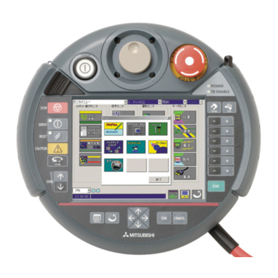
1. Before use Since this teaching pendant R57TB/R56TB (T/B) carries GUI, you can use it easily by operating the touch panel. The operation method of T/B in the instructions manual of the separate volume is indicated based on R33TB/R32TB. Please refer to this book, when using R57TB/R56TB. -
Page 16: Connection With Controller
2. Connection with controller Installing and removing the T/B, with turning off the controller power. If T/B is Installed and removed in the state of control source ON, emergency stop alarm will be occurred. If you use the robot wherein T/B is removed, install the dummy connector of attachment for the product instead of T/B. -
Page 17: Specification
3. Specification 3.1. Specifications Items Specifications Remarks Outline dimensions 252(W) x 240(H) x 114(D) (refer to outline drawing) Mass The cable is not Approx. 1,250g included. Connection method Connection with controller and round connector Cable length 7m Interface RS-422 For connection with robot controller Ethernet(10BASE-T)... -
Page 18: Construction
3.2. Construction 19) 20) 37.2 55.3 21.5 1) TEACH button 12) HOME button This changeover switch is used to enable or Return the robot to the Home position that set disable the T/B key operations. The lamp beforehand. This function is available with (white) lights up during enabling state. -
Page 19: Basic Operation Method
4. Basic operation method The basic operating method of R56TB is shown. 4.1. Operating method of R56TB As shown in the figure, holds with one hand and operate the enable switch by finger, and operate the screen and button by another hand. Since the screen is the touch panel, operate it with a touch stylus. -
Page 20: Operation Of Menu Panel
5. Operation of menu panel If the control power of the controller is turned on, the splash window () will be displayed on the screen of T/B and the initial screen () will be displayed on it in the about 15 seconds. You can confirm the connecting state between the T/B and the controller () (Left: RS-422, Right: Ethernet, Blue: connecting, Red: disconnected). -
Page 21: Language Setting
6. Language setting At the time of the first power supply on, the language setting screen is displayed. Please select the language to make it display on the T/B screen. Please tap [OK] Key. Japanese display: Japanese English display: English 7. -
Page 22: Robot Serial Setting
7.2. Robot serial setting Set the serial number of the robot arm. Tap [Robot serial setting] button and display the setting screen of serial number. Tap [Edit] button and display the setting screen. Input the serial number which has been described to the plaque of the robot. Tap [Enter] button, then Tap [Write] button. -
Page 23: Setting A Target Robot For Using Multi-Mechanism Control
8. Setting a target robot for using multi-mechanism control When using the multi-mechanism control, please select a target robot at the Select robot combo box. The robot selected here becomes the object of the following operations and monitors. Servo ON/OFF JOG operation Hand operation Direct execution... -
Page 24: Jog Operation
9. JOG operation 9.1. Speed setting Push [OVRD (Upper arrow)] or [OVRD (Lower arrow)] button () of T/B, and change operation speed. LOW – HIGH – 3% - 5% - 10% - 30% - 50% - 70% - 100% The changed speed is displayed on STATUS NUMBER of the controller, and on the combo box in the screen lower left of T/B. -
Page 25: Jog Mode
9.2. Jog mode There are JOINT, XYZ, TOOL, 3-axis XYZ, Cylinder and the WORK in jog mode. Push the [JOG] button () of T/B, the JOG operation screen will be displayed. The jog mode is changed in order of JOINT->XYZ->TOOL->3-axis XYZ->Cylinder->WORK, each time the button is pushed. The current jog mode is displayed in the combo box. -
Page 26: Switching Tool Data
9.3. Switching Tool Data Beforehand the tool data setting as MEXTL1 – MEXTL*(It is different depending on the specification of the robot controller connected) can be selected. If tool data not change, this operation is not necessary. Tool data can be selected also from combo box. () ... -
Page 27: Switching Base Coordinates
CAUTION When the robot moves with changing tool data, the tool data needs to be changed by setting tool number into the M_TOOL. To move the robot to the position where teaching was performed while switching tool data (MEXTL* parameters) during the automatic operation of the program, substitute the M_TOOL variable by a tool number when needed, and operate the robot by switching tool data. -
Page 28: Joint Jog Operation
9.5. JOINT jog operation Push the [TEACH] switch and enable the T/B. The LED (white) lights up. Press the [JOG] button () of T/B and display the JOG operation screen. Select jog mode (JOINT).Enable switch Servo switch Jogging movement is in the servo power supply ON state, and execute jog feeding by pushing the button of each axis (), continuing pushing the enable switch of T/B. -
Page 29: Xyz Jog Operation
9.6. XYZ jog operation Push the [TEACH] switch and enable the T/B. The LED (white) lights up. Push the [JOG] button () of T/B and display the JOG operation screen. Select jog mode (XYZ).Enable switch Servo switch Jogging movement is in the servo power supply ON state, and execute jog feeding by pushing the button of each axis (), continuing pushing the enable switch of T/B. -
Page 30: Tool Jog Operation
9.7. TOOL jog operation Push the [TEACH] switch and enable the T/B. The LED (white) lights up. Push the [JOG] button () of T/B and display the JOG operation screen. Select jog mode (TOOL).Servo switch Enable switch Jogging movement is in the servo power supply ON state, and execute jog feeding by pushing the button of each axis (), continuing pushing the enable switch of T/B. -
Page 31: 3-Axis Xyz Jog Operation
9.8. 3-axis XYZ jog operation Push the [TEACH] switch and enable the T/B. The LED (white) lights up. Push the [JOG] button () of T/B and display the JOG operation screen. Select jog mode (3-axis XYZ).... -
Page 32: Cylinder Jog Operation
9.9. Cylinder jog operation Push the [TEACH] switch and enable the T/B. The LED (white) lights up. Push the [JOG] button () of T/B and display the JOG operation screen. Select jog mode (Cylinder).Servo switch Enable switch Jogging movement is in the servo power supply ON state, and execute jog feeding by pushing the button of each axis (), continuing pushing the enable switch of T/B. -
Page 33: Work Jog Operation
9.10. Work jog operation Push the [TEACH] switch and enable the T/B. The LED (white) lights up. Push the [JOG] button () of T/B and display the JOG operation screen. Select jog mode (WORK). By the WORK jog operation, the robot can be moved along the work coordinate that set beforehand. The WORK jog function is available with Ver.2.3 or later of this software. -
Page 34: Jog Operation With Wheel
While setting the operation speed to fixed-dimension feed High or Low, it is possible to operate by even rotating the wheel , in addition to the usual jog operation done with [+] and the [-] key. (This function is available with R56TB Ver.2.1 or later.) ... -
Page 35
2. Tap a part of axis name
of axis to operate on the JOG operation screen, the axis becomes the target axis for the operation. If the target axis is set, it becomes Wheel-jog mode. And the Wheel-mark is displayed. If tapping other axis name, the target axis changes into that axis. -
Page 36: Force Control Function
9.12. Force control function If the force control function is can be used, [F] bottom is displayed in the Jog operation screen. Tap [F] bottom, [force control screen] is displayed. The force control function is available with Ver.3.0 or later of this software. -
Page 37: Collision Avoidance On/Off
9.13. Collision avoidance ON/OFF If the collision avoidance function is can be used, [CAV] combo box is displayed in the Jog operation screen. Select [CAV] combo box ON/OFF, The collision avoidance function when Jog is operated can be turned ON/OFF. -
Page 38: Aligning The Hand
9.14. Aligning the Hand The posture of the hand attached to the robot can be aligned in units of 90 degrees. This feature moves the robot to the position where the A, B and C components of the current position are set at the closest values in units of 90 degrees. -
Page 39: Opening/Closing The Hands
9.15. Opening/Closing the Hands Push the [HAND] button () of T/B and display the hand operation screen. In this software version 2.5 or later, the Electric Hand screen is displayed when the robot has the Electric Hand. The Electric Hand operation screen and the Normal Hand operation screen can be switched by the button in the hand operation lower right of the screen. -
Page 40: Operation Of The Electric Hand
9.15.1. Operation of the Electric Hand The Electric Hand operation function can be used this software Version 2.5 or later. And the software version of the controller which you can use is as follows. Controller Software version of the controller CR750-D/CRnD-700 Version S2a or later CR750-Q/CRnQ-700... -
Page 41
(2) In the case of using version 3.1 or later Specify the point method Specify the table method
[Switch checkbox] Push the [HAND] button () of T/B and display the Electric Hand operation screen. When the Normal Hand operation screen is displayed, the Electric Hand operation screen can be displayed by tapping the lower right [Electric] key ... - Page 42 Table 9-3 The operation of the Electric Hand and the explanation of the functions. Operation Explanation Open The hand is opened. (Only while holding down the button.) The same operation as time when the EHOpen instruction was executed is done based on a set value of the "Speed"...
-
Page 43
The explanation of “HAND”
is as follows. Table 9-4 The explanation of the state of the Electric Hand. Explanation Status (*2) (*1) Ready Preparation is completed. During the preparation. Servo Servo ON Servo OFF Moving to the origin point is Moving to the origin point is not Origin completed. -
Page 44: Operation Of The Normal Hand
9.15.2. Operation of the Normal Hand Push the [HAND] button () of T/B and display the hand operation screen. When the Electric Hand operation screen is displayed, the Normal Hand operation screen can be displayed by tapping the lower right [Normal] keyof the screen. The Electric Hand operation screen is available from this software version 2.5 or later. -
Page 45: Return To The Home Position
9.16. Return to the Home position Return the robot to the Home position that set beforehand. The robot is initiated a joint interpolation movement to the position set by the parameter "JSAFE". The speed is determined by the override setting. This function is available with Ver.2.3or later of this software. -
Page 46: Usb Memory Stick
10. USB memory stick USB memory stick Note) The operation method is the same although the photograph shown below differs from the actual product slightly. 10.1. Plug-in the USB memory stick CAUTION Never unplug the USB memory stick during accessing (read / write operations). It causes the failure. -
Page 47: Unplug The Usb Memory Stick
10.2. Unplug the USB memory stick CAUTION Never unplug the USB memory stick during accessing (read / write operations). It causes the failure. Please shut the cover surely after unplugging the USB memory stick. Otherwise the foreign body enters the connector, and it causes the malfunction. This picture is sample. -
Page 48: Program Edit
11. Program edit 11.1. Edit of program 11.1.1. Open an edit display (new creation) 1) Tap the [MENU] button () of a T/B screen and display menu panel. Menu panel Initial screen 2) [Program] button () is tapped and a program list is displayed. At this time, if it creates newly to a robot controller, the [Robot] radio button () is checked. -
Page 49
4) If a program name is inputted by the keyboard of a screen and the [Enter] key (
) is tapped, a command edit screen will be displayed. The inputted character is displayed on "Program" Keyboard Command edit screen (Creates to the robot controller) Command edit screen (Creates to the USB memory) Advice... -
Page 50: Open An Edit Display (Read Of The Existing Program)
11.1.2. Open an edit display (read of the existing program) 1) Tap the [MENU] button () of a T/B screen and display menu panel. Initial screen Menu panel 2) [Program] button () is tapped and a program list is displayed. At this time, if it creates newly to a robot controller, the [Robot] radio button () is checked. -
Page 51
3) Select the program to read
and tap the [Open] button. ( ) The command edit screen is displayed. Even if it double taps the program to read , the command edit screen is displayed. Command edit screen (Reads from the robot controller) Command edit screen (Reads from the USB memory) -
Page 52: Save (Robot Controller)
11.1.3. Save (robot controller) Tap the [Save & Close] button () of the edit screen. During the save, the screen is displayed during communication, () and if it completes, it will return to the program list. Advice The buttons displayed differ by the case where the edit screen targets the robot controller and the case where the edit screen targets the USB memory. -
Page 53: Save (Usb Memory)
11.1.4. Save (USB memory) Tap the [Save] button () of the edit screen. Since the confirmation screen is displayed, the [Yes] button () is tapped if it saves. The [No] button () is tapped if it does not save. During the save, if the sandglass is displayed and it completes, it will return to the original edit screen. -
Page 54: Close The Edit Screen
11.1.5. Close the edit screen Tap the [RETURN] button () at the lower right of the T/B screen. It returns to the program list display. At this time, if the command and the position variable are edited and save operation is not performed, display the message of the confirmation. -
Page 55: Add The Command Line
11.1.6. Add the command line Operation of adding the line of code to new or the existing program in the command edit screen is shown. 1) Taps of the [Add] button () of the command edit screen will display the keyboard. ... -
Page 56: Delete The Command Line
11.1.7. Delete the command line Operation of deleting the line of code or the position variable is shown. 1) Select the line to delete or the position variable. Two or more lines can be selected. () 2) Tap the [Delete] button (), the selected line of code or the position variable will be deleted. -
Page 57: Undo The Edited Contents
11.1.8. Undo the edited contents When editing the command line of the program in the USB memory, the editing operation can be returned to the last state only once. If the [Menu] button of the command edit screen is tapped and "Undo" () is tapped after the mistaken operation, the operation done last time will return. -
Page 58: Cut, Copy And Paste
11.1.9. Cut, Copy and Paste The specified line of code can be cut, past or copy. 1) Select the line to cut or copy. Two or more lines can be selected. () 2) Tap the [Menu] button of the command edit screen, and if it move, tap the "Cut (Line)." () or if it copies, tap the "Copy". -
Page 59
4) The screen which confirms the putting part in the destination of the movement or the copy is displayed. Select ahead or after of the line for pasting, and tap [OK] key
. And the command line is added to the selected part ... -
Page 60
6) It returns to the Paste lines screen. Tap [OK] button
if the setup is completed, [Edit] button for setting up again, [Cancel] button for stop pasting. CAUTION If the new line number of past replace (copy place) has already existed, the existing line of code is overwritten. -
Page 61: Renumber
11.1.10. Renumber The renumbering function can only be used with MELFA-BASIC IV. The row number of the existing program can be reassigned. When the program is changed several times and the margin has been lost to the line pitch, it can utilize effectively. All lines of code and the range can be specified. 1) Tap the [Menu] button of the command edit screen and tap the "Renumber". -
Page 62
4) Renumber will be executed if you tap the [OK] button (
) of setting screen. If the object range is specified, display the message that the row number after the renumber has already existed. In this case, the renumber is not executed. Tap the [OK] button. ( ) ... -
Page 63: Automatic Numbering
11.1.11. Automatic numbering When MELFA-BASIC IV is used, the line number can be generated by the automatic operation in the command edit screen. This function automatically displays the next line number each time the edit command dialog is displayed. The start line No. -
Page 64: Search
11.1.12. Search If the program of the USB memory is being edited, the specification character string can be searched with command edit. It can be specified whether the capital letter/small letter is differentiated or not. 1) Taps the [Menu] button and select the "Find" () of the command edit screen, the setting screen will be displayed. -
Page 65
If the "Match case" (
) is checked at this time, the capital letter and the small letter will be differentiated. Moreover, the search direction can be specified with checking Up/Down. ( ) Display the message, if the character string is not found. Taps the [OK] button. ( ) ... -
Page 66: Replace
11.1.13. Replace If the program of the USB memory is being edited, the specification character string can be replaced by command edit. It can be specified whether the capital letter/small letter is differentiated or not. 1) Taps the [Menu] button and select the "Replace" () of the command edit screen, the setting screen will be displayed. -
Page 67
Display the message, if the character string to search is not found. Tap the [OK] button. (
) 4) Tap the [Close] button ( ) to finish. Advice Only last one operation is valid to undo. All cannot be returned if two or more operations have been mistaken. In this case, it is necessary to finish program edit, without saving and to do over edit from the start. -
Page 68: Jump
11.1.14. Jump The program jumps to the designated label or line number. To carry out jumping, tap the [Jump] button. 1) Tap the "Jump" button () of the command edit screen. The setting screen will be displayed. 2) To input the label or line number, tap the [Edit] button (), and uses the keyboard that displayed. Tap the [Enter] key () of the keyboard to finish the input. -
Page 69
If the specified row number does not exist, jump to the near place. Display the error message, if the specified label does not exist. Tap the [OK] button (
), close the error message window, and try again. ... -
Page 70: Editing The Position Variable
11.2. Editing the position variable Edit the position on the position edit screen. Push the [XYZ], [XYZ (Global)], [Joint], or [Joint (Global)] button. () The position editing screen will appear. (Position type variable) [XYZ] ....Position type variable [XYZ (Global)] ..Position type variable (System variable) [Joint] ...... -
Page 71
3) If the [Get current position] button (
) of the data edit screen is pushed, will take in the robot's current coordinate value. 4) Tap the [OK] button ( ) and register the data. ... -
Page 72: Edit Of Position Data
11.2.2. Edit of position data The procedure of direct input of the numerical value is shown. 1) Select the variable of editing and tap the [Edit] button. () The data edit screen is displayed. 2) Tap the [Edit value] button. () The data input screen is displayed. ... -
Page 73
4) The structure flag can be edited by the [Edit FLG1] button. (
) The multi-rotation flag can be edited by the [Edit FLG2] button. ( ) Tap the [OK] button, ( ) will fix the data. 5) The [OK] button ( ) will be tapped if edit of all the data is completed. The position variable data is registered. -
Page 74: Addition Of Position Data
11.2.3. Addition of position data Although the position variable used by the command line is displayed on the screen, it can add newly. 1) Tap the [Add] button. () The position edit screen is displayed. 2) The [Edit] button () is tapped and input the variable name from the keyboard displayed, and tap the [Enter] button () to fix it. -
Page 75: Deletion Of Position Data
11.2.4. Deletion of position data The procedure of deletion of position data is shown. The variable currently used by the command line cannot be deleted. Select the variable of deleting and tap the [Delete] button. () The selected position variable is deleted. ... -
Page 76: Confirming The Position Data (Position Jump)
11.2.5. Confirming the position data (Position jump) The robot can be moved to the teaching position and the position can be checked. The interpolation method is the current jog mode. By jog operation, move the robot to the safe position beforehand. Select the target position variable and tap the [Pos. - Page 77 CAUTION By jog operation, move the robot to the safe position beforehand and do this movement. Failure to do so could lead to interference with the work piece or peripheral devices. The key is separated to stop the robot or the enable switch is separated or it strongly pushes it.
-
Page 78: Find
11.2.6. Find The procedure of finding the position data is shown. 1) Tap the [Find] button. () The variable name input screen is displayed. 2) Tap the [Edit] button. () The string input screen is displayed. 3) The variable name to find is inputted, tap the [Enter] button (), and finish the string input. ... -
Page 79: Editiong The Position For Sq Direct Function
4) Tap the [OK] button. () The variable to find is displayed. 11.3. Editiong the position for SQ Direct Function The SQ Direct Function (PLC Direct Function) is available with Ver.2.3 or later of this software. And this function is available with Ver.P8 or later of CRnQ-700 series controller software. - Page 80 CAUTION In the SQ Direct Function, the position data that can be used is only the Position type variable.
-
Page 81: Registering The Current Position Data For Sq Direct Function
11.3.1. Registering the current position data for SQ Direct Function The procedure of registering the robot's current position is shown. 1) By jog operation, move the robot to the teaching position beforehand. 2) Select the position data to teach () and tap the [Teach] button (). The current position can be taught. In the same time, the position data is written to the controller. -
Page 82: Edit Of Position Data For Sq Direct Function
11.3.2. Edit of position data for SQ Direct Function The procedure of direct input of the numerical value is shown. 1) Select the position data to edit () and tap the [Edit] button (). The data edit screen is displayed. () 2) Tap the [Edit value] button ( ). -
Page 83: Addition Of Position Data For Sq Direct Function
11.3.3. Addition of position data for SQ Direct Function The 999 points of position data, 1 to 999, in the controller which can use the SQ Direct Function are displayed in the list. When position data other than selected one is edited, use the [Add] button of the SQ Direct position edit screen. -
Page 84: Initialization Of Position Data For Sq Direct Function
11.3.4. Initialization of position data for SQ Direct Function Select the position data to initialize (), and tap the [Delete] button (). The confirmation message is shown up, after that tap the [Yes] button. The values of selected position data are initialized. ... -
Page 85: Copy Position Data For Sq Direct Function From Controller To Usb
11.3.7. Copy position data for SQ Direct Function from controller to USB Since this software Ver.2.3, “*SQ Direct” is displayed in the top of the program list when connecting with controller which can use the SQ Direct Function. 1) Select the [Robot] in the Program list screen, select the “*SQ Direct” () in the list, and tap the [Copy/Move] button (). -
Page 86: Copy Position Data For Sq Direct Function From Usb To Controller
11.3.8. Copy position data for SQ Direct Function from USB to controller 1) Select the [USB] in the Program list screen, select the file of position data for SQ Direct Function () in the list, and tap the [Copy/Move] button (). The Copy/Move screen will appear. The files of position data for SQ Direct Function are saved as extension “sdp”. -
Page 87: Edit Of Position Data For Sq Direct Function In The Usb Memory
11.3.9. Edit of position data for SQ Direct Function in the USB memory 1) Select the [USB] in the Program list screen, select the file of position data for SQ Direct Function edited () in the list, and tap the [Open] button (). 2) The SQ Direct position edit screen is displayed. -
Page 88: Debugging
12. Debugging Debugging refers to testing that the created program operates correctly, and to correcting errors if an abnormality is found. These can be carried out by using the T/B's debugging function. Always carry out debugging after creating a robot program, and confirm that the program runs without error. 12.1. -
Page 89: Step Operation
12.2. Step operation "Step operation" executes the program line by line. The operation speed is slow, and the robot stops after each line, so the program and operation position can be confirmed. During execution, displayed by turns at the lower left of the T/B screen, and if execution is completed, displayed at there. -
Page 90: Continuous Execution
12.2.3. Continuous Execution Push continually the sheet-key “+” key corresponding to the “FORWD”. This executes the program continuously from the current line. 12.2.4. Skip This function is available with Ver.2.3 or later of this software. Push the sheet-key “+” key corresponding to the “SKIP”, and the executing line of the program that has been selected now can be put forward by one line without run. -
Page 91: Step Forward In Another Slot
12.2.5. Step forward in another slot When checking a multitask program, use with the “Program monitor” window, it is possible to do step operation in another slot. 1. In the “Program monitor“, select the slot with “task slot”. () 2. Tap the “Debug” button. () 3. -
Page 92: Setting And Deleting Breakpoints
If you set a breakpoint, you can stop the program at the line while executing the Continuous execution. After stops, you can execute the program continuously. (This function corresponds to the R56TB Ver.2.1 or later.) Breakpoints can be set up to 128. Moreover, when the program is quitted, every breakpoint is deleted. -
Page 93: Program Management
13. Program management The program files can be copied, moved, deleted, protected, renamed and the contents compared. 13.1. Starting Select the “Program” from the menu, and program list shown below appears. Since this software Ver.2.3, “*SQ Direct” is displayed in the top of the program list when connecting with controller which can use the SQ Direct Function. - Page 94 CAUTION There are some restrictions of operating the files for SQ Direct Function. Proprieties of operation are as follows. The name of the file for SQ Direct Function is fixed as “*SQ Direct” in the controller. In the USB memory, the file name can be set free. However, the extension is “sdp”. o : Can be operated.
-
Page 95: Program List
13.2. Program list The lists of the program files are displayed. For programs in the robot controller, the "Name", "Size", "Date", "Time", as well as the "Protect information", "No. of lines", "No. of position variables", "Latest cycle time", "Average cycle time", "Operation time", "No. of cycles" and "Comment“... -
Page 96: Copy
13.3. Copy The program files are copied. Copying of the entire program file or only the command statements or only the position variables is possible. Tap the [Copy / Move] button on "Program list window", and “Copy / Move” window will appear. ... -
Page 97: Move
13.4. Move The program files can be moved. Tap the [Copy / Move] button on "Program list window", and “Copy / Move” window will appear. 1) Select the program files to move from the “Source” list, and designate the destination (robot or folder in the USB memory) at the “Destination”... -
Page 98: Protect
13.6. Protect The program files in the robot controller can be protected. The entire program file can be protected, or just the command statements or position variables can be protected. 1) Select the program files to be protected from the lists. The multiple program files can be selected at the same time. -
Page 99: Compare
13.8. Compare The program files can be compared. Compare of only the command statements or only the position variables is possible. Tap the [Compare] button on "Program list window", and “Compare” window will appear. 1) Select the program files to be compared from the left and right lists. 2) Tap the [Compare] button (), and “Setting for compare”... - Page 100 CAUTION The method of comparing position variables is changed since this software Ver.2.3. When comparing the programs by Ver.2.2 or before of this software, position variables were judged different if the expression of value of each elements are different as follows. Since Ver.2.3, it is changed to judge the same position variable when the value of each element of a position variable is coincides.
-
Page 101: Select Program
13.9. Select program Even the controller which the operation panel is not installed can select the program from this T/B. This function is available with Ver.2.3 or later of this software. 1) Set the mode of the controller to "AUTOMATIC". 2) Make the T/B enable. -
Page 102: Backup/Restore
14. Backup/Restore The information on the robot controller can be backed up to the USB memory, or the backup information saved on the USB memory can be restored to the robot controller. Backup (Robot -> USB memory) Saves the backup data on the robot controller to the USB memory. -
Page 103: Backup (Robot -> Usb Memory)
14.2. Backup (Robot -> USB memory) Save the information on the robot controller to a file on the USB memory. Tap the [Backup] button. The following window appears. << Backup >> All Files : Saves all files (robot program, parameter files, etc.) in the robot controller into the designated folder. -
Page 104: Restore (Usb Memory -> Robot)
14.3. Restore (USB memory -> Robot) The backup data saved in the USB memory is transmitted to the robot controller. Tap the [Restore] button. The following window appears. << Restore >> All Files : Transfers all files (except BKUP.SYS and MECHA.SYS) in the designated folder to the robot controller after all information in the robot controller is cleared (initialized). - Page 105 A backed up file is transferred. However, as for the origin data and the parameters for recovering Transfers a backed up file as is. The origin data is positions, the information inside the controller is replaced. retained. Valid only when [All Files] or [Parameter Files] is selected under [Backup]. Change robot arm serial number If checked : Replaces serial number of the robot arm in the robot controller with the contents of the...
- Page 106 CAUTION Precaution for Restore When a program is running or the ALWAYS program is set up If a batch restoration or a program restoration is executed when the program is being started, the program will automatically be stopped. At this time, if there is an error in the controller, the program in operation cannot be stopped, and the message shown on the below will be displayed.
-
Page 107: Power Reset Of The Robot Controller
14.4. Power Reset of the Robot Controller To make the restored information effective, it is necessary to power on the robot controller again. If connecting to the CR800-D/CR750-D/CR751-D/CRnD-700 series controller, the power reset of the robot controller can be performed from the T/B. If connecting to the CR800-R/CR800-Q/CR750-Q/CR751-Q/CRnQ-700 series controller, please reset the power by switch of the robot controller. -
Page 108: Monitor
15. Monitor With the monitor, all of the information in the currently connected robot controller can be constantly displayed. 15.1. Starting Select the "Monitor" from the Menu. The "Monitor menu" shown below will appear. After selecting the robot you wan to monitor, tap an item. The monitor window for selected robot appears. -
Page 109: Outline Of Each Function And Starting Methods
15.2. Outline of each function and starting methods 15.2.1. Outline of each function Each monitor function is explained briefly in this section. The monitor functions are largely classified into the following three groups. 1. Robot movement monitor ..…Items related to robot movement are monitored. 2. -
Page 110: Each Monitor Function
15.3. Each monitor function Each monitor function is explained in this section. 15.3.1. Robot movement monitor 15.3.1.1. Slot run state The state of the slots in the robot controller can be monitored. The No. of displayed slots is determined with the parameters. It is possible to stop all slots for which the start condition is "ALWAYS"... -
Page 111: Program Monitor
15.3.1.2. Program monitor Information of the running program can be monitored. 1) Program monitor [Watch] : The constant display window for the variables used in the running program is displayed. [Debug] : The “Debugging” window will appear at the right of T/B. For debugging, please refer to the “12 Debugging”. - Page 112 2) Watch monitor With the watch monitor, the variables to be constantly displayed can be selected. When the [Watch] button on "Program monitor window" is tapped on, the watch monitor window and a window for selecting the variables to be displayed will appear. ...
-
Page 113
[Add Variable] The variables to be monitored can be designated. Input the variable in Variable Name, select the variable type, and then tap on the [OK] button. (
) [Change value] The value of the variable being watched now is changed. Variable identifier to which the value is changed is double tapped or [Change value] button ( ) is tapped while ... -
Page 114: Movement State
[Delete variable] The value of the variable being watched now is changed. Variable identifier to which the value is changed is tapped double or [Change] button is tapped while selected.Variable value change window is displayed. About the hexadecimal number display The variable displayed with "Watch monitor"... -
Page 115: Error
15.3.1.4. Error The errors currently occurring in the robot controller are displayed. 1) Currently occurring errors... - Page 116 2) Error history The history of errors that have occurred in the past can be referred to. This display is not shown at all times.
-
Page 117: Signal Monitor
15.3.2. Signal monitor 15.3.2.1. General-purpose signal The status of the input / output signals can be monitored.When the [Pseudo-input] button is tapped on, the robot controller will enter the "pseudo-input mode, and the following window will appear. - Page 118 1) General-purpose signal monitor With the general-purpose signal monitor, monitoring can be carried out by designating the head signal No. and number of signals to display. Please tap the [Monitor setting] button. () 2) Pseudo-input In the pseudo-input mode, the state input from the following window is interpreted as the input signal instead of the robot controller general-purpose input signals.
-
Page 119
3) Forced output The robot controller's general-purpose signals can be forcibly output. Tap on the [Forced output] button. (
) A window for forcibly outputting the signal will appear. i) First, read out the signal to be forcibly output. 16 signals can be output simultaneously. -
Page 120: Named Signal
15.3.2.2. Named signal The status can be checked by naming the status of the dedicated I/O signal that has been set in the robot controller, as well as each bit or within the range of 32 bits of the general-purpose signal. The signal file in the robot controller is loaded at startup. -
Page 121: Stop Signal
[Load] / [Save] / [Delete signal file in robot]The edited result can be saved on or loaded to a personal computer or robot controller. Specify the save destination / load destination and tap the [OK] button. If the save destination is a personal computer, a file name can be specified. -
Page 122: Register
15.3.2.4. Register This screen cannot be referred to if the CC-Link option card is not mounted on the robot controller. The values of the CC-Link function input registers can be monitored.1) Monitor setting The register to be monitored can be changed. Please tap the [Monitor setting] button. () -
Page 123
2) Pseudo-input With the pseudo-input mode, the values input from the following window will be interpreted as the input register values instead of the registers input from an external source.
First, read out the registers to be pseudo-input. Up to 16 sequential registers can be set simultaneously. - Page 124 15.3.2.5. I/O unit monitor The XY device variables of I/O unit can be monitored. The status of input signals are displayed on the upper table, and the status of output signals are displayed on the lower table. The signal values can display a 16-bit integer with a mark, or 32-bit integer with a mark by the decimal number or the hexadecimal number.
-
Page 125: Operation Monitor
15.3.3. Operation monitor 15.3.3.1. Operating hours The robot operating time, and battery usage time, etc., can be confirmed. 15.3.3.2. Production information The latest cycle, operation time, No. of cycles and average cycle time for each program in the robot controller can be confirmed. -
Page 126: Additional Board Information
15.3.3.3. Additional board information Information on the option card mounted on the robot controller can be confirmed. Note that this screen cannot be referred to if robot controller is not provided with a slot for mounting the option card. -
Page 127: Servo Monitor
15.3.4. Servo monitor The servo system is monitored. When the [Reset] button is tapped of each screen, the maximum value and the minimum value of all monitoring servo information of position, speed, current, load and power are reset by the batch. 15.3.4.1. -
Page 128: Speed
15.3.4.2. Speed The following data concerting the rotational speed of each axis motor can be monitored. Speed feedback A present motor speed is displayed by the unit of rpm. Speed MAX. The maximum value of the speed feedback after robot controller’s power supply is turned on is displayed. When the [Reset] button on the screen is tapped, this value is reset in 0. -
Page 129: Current
15.3.4.3. Current Data concerning the current value of each axis motor can be monitored. The displayed data changes by tapping the [Current1] button () and the [Current2] button () on the screen. The following data can be monitored in the [Current1]. Current cmd The current command of the motor is displayed. - Page 130 Current2 ...
-
Page 131: Load
15.3.4.4. Load The load state of each axis motor and the temperature of the encoder (Only the robot that corresponds to the function of the encoder temperature) can be monitored. The following data can be monitored. Axis load level A preset load ratio of each motor is displayed as an alarm level. The overload error occurs when this value reaches 100%. -
Page 132: Power
15.3.4.5. Power The following data concerning robot controller’s main circuit power supply can be monitored. Motor power voltage A present power-supply voltage value is displayed. Motor power voltage (MAX) The maximum value of the motor power voltage in servo ON is displayed. When the [Reset] button on the screen is tapped, this value is reset in 0. -
Page 133: Maintenance
16. Maintenance There are functions of concerning the system construction of the robot in "Maintenance" menu. Maintenance menu is shown by following operation. Version Menu Maintenance menu 16.1. Origin data The origin is set so that the robot can be used with a high accuracy. After purchasing the robot, always carry out this step before starting work. -
Page 134: Origin Data Input
16.1.1. Origin data input The origin data to be input is noted in the origin data sheet enclosed with the robot arm, or on the origin data history table attached to the back side of the robot arm cover. “DJNT” value is used by the position repair tool in RT ToolBox. (1) Edit origin data If origin data is changed, tap [Edit] button () and shown the following window. -
Page 135: The Others (Mechanical Stopper, Tool, Abs, User Origin Method)
(3) Save to file, Read from file in T/B Tap [Save to file] button (), the current origin data is saved into the designated file. Tap [Read from file] button (), the origin data in the designated file is loaded. ... - Page 136 (2) Display of method of setting origin position The method of origin position set last time is displayed. (This function corresponds to the R56TB Ver.2.1 or later.) Tool Green Light blue User origin method Yellow Mechanical stopper (3) Release the brakes If you need move axis with brake by the hand, please release the break and work by two people.
-
Page 137: Initialize
16.2. Initialize “Initialize” has four functions. 1. Setting the controller’s date and time. 2. Erase all programs in the controller. 3. Initialize the battery remaining time. 4. Set a serial number 16.2.1. Setting the controller’s date and time Tap the [Set time] button (). Set the present date and time, and tap the [OK] button. -
Page 138: Erase All Programs In The Controller
16.2.2. Erase all programs in the controller To delete all programs, follow the procedure below. (1) Tap the [Initialize] button of “program”. (2) Tap the [Edit] button of the confirmation screen. (3) Input "YES" with the keyboard, and tap the [Enter] key. (4) Tap the [OK] button... -
Page 139: Serial Number
16.3. Serial number The serial number of the robot arm is set (Each mechanism can be set). The serial number of the robot arm has been put on the back of the body of the robot base. 16.3.1. Serial Number setting (1) Tap on [Set] button ... - Page 140 (2) Tap on [Edit] button of the serial number setting. Input the serial number from the displayed keyboard. After the serial number is input, tap on [Enter] key of the keyboard. (3) Tap on [Write] button to write into the controller. After writing, last updated date and time is updated.
-
Page 141: Save Serial Number To File
16.3.2. Save serial number to file (1) Tap on [Save to file] button of the serial number setting. (2) When [Save] button is tapped specifying the file name, serial number is saved in a specified file. Save serial number to file ends above. 16.3.3. -
Page 142: Releasing The Brakes
16.4. Releasing the brakes This function releases the servomotor brakes when the servo is OFF. This function is used to directly move the robot arm by hand, etc. -
Page 143: Preparation For Releasing The Brakes
16.4.1. Preparation for releasing the brakes Before releasing the brakes, it is necessary to do the following operation. 1. Set the mode of the controller to “MANUAL”. 2. [TEACH] button is set to ON. 3. Push the enable switch. 4. Press the CAUTION button. Another person supports the Robot arm which releases brake. -
Page 144: Releasing The Brake Of One Axis
16.4.2. Releasing the brake of one axis For releasing the brake of one axis, press [+] button of J1~J6 after doing (1) operation. The brake is released only while the button is being pressed. 16.4.3. Releasing the brakes of two of more axes For releasing the brakes of two or more axes, do following operation after doing (1) operation. -
Page 145: Maintenance Forecast
16.5. Maintenance Forecast In Maintenance Forecast, the parts replacement (grease replenishment, battery and belt replacements) times can be checked from the up-do-date operating data collected inside the controller. 16.5.1. Start Tap [Maintenance Forecast] button on Maintenance menu. The Maintenance Forecast window appears. 16.5.2. -
Page 146: Forecast (Grease)
16.5.3. Forecast (Grease) When [Grease] is seen in Item, the "hours until grease replenishment time" can be checked for each axis. If the hours until replenishment time has reached (Hours until replenishment time) < ([The remainder days until presumed maintenance time] on the Setup screen) x ([Operation time of a day]), the hours and bar graphs are displayed in orange. -
Page 147: Forecast (Belt)
16.5.4. Forecast (Belt) When [Belt] is seen in Item, the "hours until belt replacement time" can be checked for each axis. If the hours until belt replacement time has reached (Hours until belt replacement time) < ([The remainder days until presumed maintenance time] on the Setup screen) x ([Operation time of a day]), the hours and bar graphs are displayed in orange. -
Page 148: Gear
16.5.5. Gear You can refer to "time until reduction gear reducer". This screen can be displayed only when connected to the CR800 series robot controller. If the hours until replenishment time has reached (Hours until replenishment time) < ([The remainder days until presumed maintenance time] on the Setup screen) x ([Operation time of a day]), the hours and bar graphs are displayed in orange. -
Page 149: Setup
16.5.6. Setup Tap the Setup button. Here, the timing to collect the information for Maintenance Forecast, the notification method and other items can be set up. When the [Write Parameters] button () is tapped after setting each item, the setting values are written into the controller. - Page 150 Tab. Setup Screen Factory Item Explanation preset value (1) Maintenance Forecast is If this is checked, the Maintenance Forecast function takes effect. Check ON made effective. *If a checkmark is removed, the collection of the information for Maintenance Forecast stops, and the correct maintenance times cannot be calculated.
-
Page 151: Reset
16.5.7. Reset When axes were exchanged or replenished by generating warning of the Maintenance forecast function to urge the battery exchange, the grease replenishment, and the belt exchange, the axes which executes the exchange and replenishment should reset information accumulate among controllers. The information (about battery, grease and belt) for Maintenance Forecast kept in the controller can be reset. - Page 152 When the [Log] button is tapped in the upper-right corner of the window, the previous reset date/time and reset count can be checked. However, the battery reset count is not displayed. If no reset has not made previously, “----/--/-- --:--:--“ is displayed.
-
Page 153: Others
16.5.8. Others The information for Maintenance Forecast kept in the controller can be backed up and/or restored. CAUTION The data related to preventive maintenance / predictive maintenance is not backed up and/or restored. Even if the robot controller supports the preventive maintenance / predictive maintenance function, only the maintenance forecast data is backed up / restored on this screen. -
Page 154: Guidance
16.6. Guidance The guidance screen to do a basic setting to set the origin data to during start the controller first time is displayed. In this screen, the following three functions are provided. For more information, please refer to the "7 Guidance". (1) RC time setting (2) Robot serial setting (3) Origin data setting... -
Page 155: Security Function Of The Robot Controller (Password Setup)
16.7. Security function of the robot controller (Password Setup) It is possible to forbid accessing the robot programs, parameters and files in the robot controller. The security function can be achieved by setting the password to the robot controller. This function can be used with Version 3.0 or later of this software. -
Page 156: Register The Password
16.7.1. Register the Password The password is registered to the robot controller. Tap the "Register/Change" button of the item to which register the password in "Password Setup" screen. After inputting the password in the "Register/Change Password" screen, tap the [OK] button. The input password is displayed by "*". -
Page 157: Change The Password
16.7.2. Change the Password The password being set in the controller is changed. Tap the "Register/Change" button of the item to which change the password in "Password Setup" screen. After inputting a password set now and a new password in the "Register/Change Password" screen, tap [OK] button. Figure Change Password When the password is changed by "All"... -
Page 158: Delete The Password
16.7.3. Delete the Password The password being set in the controller is deleted. Tap the "Delete" button of the item to which delete the password in "Password Setup" screen. After inputting a password set now in the "Delete Password" screen, tap [OK] button. Figure Delete Password When the password is delete by "All"... -
Page 159: Tool Automtic Calculation
16.8. Tool automtic calculation With the “Tool automatic calculation”, the tool length is calculated automatically by teaching a same position by 3 to 8 points to the robot that is attaching an actual tool, and the value of a tool parameter (MEXTL) is set up. This function can be used with Version 2.20W or later of this software. -
Page 160: Flow Of Oerations
16.8.3. Flow of oerations Select the tool number for setting () Re-teaching Work Procedure Move the robot to the auxiliary point Select the line of “Auxiliary point” () Teach selection line () Repeat as necessary Enter checks to the check box of the line (When a value is set to “Calculated tool coordinate”, used to calculation () a [Write] button ( ) becomes effective) -
Page 161
Move the robot which is attaching a tool. After selecting the line of “Auxiliary point” list (), tap a [Teach selection line] button (
). Teach a same position by 3 to 8 points with different posture. (When the [Pos. jump] button ( ) is tapped, the robot can be moved to the selected position and the teaching point can be checked. -
Page 162: Parameter Editor
17. Parameter editor The parameter editor can be used to reference and rewrite the parameter information set in the robot controller. 17.1. Starting Select the “Parameter” from the menu, and parameter editor shown below appears. -
Page 163: Downloading The Parameter List (Robot Controller -> T/B)
17.2. Downloading the parameter list (Robot controller -> T/B) The message to confirm whether to download the parameter list when the parameter edit is started might be displayed. This message will be appeared in the following cases. (1) When the parameter list can be read from the robot controller or when the [Read] button () is tapped on "Parameter window"... -
Page 164: Changing The Parameters
17.3. Changing the parameters Select a parameter displayed in the list, or input the parameter name and then tap on the [Read] button () on "Parameter window". The designated parameter information in the robot controller will be appeared. After confirming the parameter, the parameter information in the robot controller can be rewritten by tapping on the [Write] button. -
Page 165: Parameter Menu
17.4. Parameter menu With this tool, parameter panels grouped as windows for each function are prepared. Select the name of the parameter to be referred to with the [Parameter menu] button () on "Parameter window". (1) The T/B version is before 3.2 ... -
Page 166: Motion Limit
17.4.1. Motion limit Set the operating range of the robot. 17.4.2. Set the speeds of joint jog and XYZ jog. Memo Override specifies maximum speed. Maximum speed can be suppressed by reducing the value. -
Page 167: Hand
17.4.3. Hand You can set the parameters of the hands which connected to the robot. "17.4.3.2 Multi-Hand Tool”, “17.4.3.3 Multi-Hand Base”, “17.4.3.5Electric hand point”, “17.4.3.6Electric hand“ can be used with Version 2.5 or later of this software. “17.4.3.4 Electric hand table” can be used with Version 3.1 or later of this software. 17.4.3.1. -
Page 168: Multi-Hand Tool
17.4.3.2. Multi-Hand Tool Selects the Hand Base of the Multi-Hand, set the offset value, set the offset value of each hand to the selected Hand Base. The Multi-Hand Tool can be connected to the robot with remote Input/Output signals or parallel Input/Output signals. - Page 169 This function is available from this software Ver.2.5 or later. Setting of offset...
-
Page 170: Multi-Hand Base
17.4.3.3. Multi-Hand Base Set the type name of the hand base for the Multi Hand and the Normal coordinates value of each hand. When the robot and the controller connected to this software correspond to the function of the 'Multi-Hand' , the item concerning the Multi-Hand are displayed in the parameter menu. -
Page 171: Electric Hand Table
17.4.3.4. Electric hand table Set parameters about the table method of the electric hand. This function is available from this software version 3.1 or later. And the controller which can set the parameters about the electric hand table is as follows. Table 17-3 Robot controller which can set the parameters about the electric hand table Controller S/W Ver. -
Page 172: Electric Hand Point
17.4.3.5. Electric hand point Teach the positions of the electric hand. This function is available from this software version 2.5 or later. And the controller which can set the parameters about the electric hand is as follows. Table 17-4 Robot controller which can set the parameters about the electric hand Controller S/W Ver. -
Page 173: Electric Hand
17.4.3.6. Electric hand Selects the type of the electric hand and set the parameters. And, please refer to “Table 17-4 Robot This function is available from this software Ver.2.5 or later. controller which can set the parameters about the electric hand” for the controller which can set the parameters about the electric hand. -
Page 174: Weight And Size (Work)
17.4.4. Weight and size (Work) Set the work conditions. WRKDAT0 might not be able to set according to the kind of the connected robot. In that case, the row of WRKDAT0 cannot be input. 17.4.5. Weight and size (Hand) Set the hand conditions. HNDDAT0 might not be able to set according to the kind of the connected robot. -
Page 175: Tool Parameter
17.4.6. TOOL parameter Set the standard tool coordinates, standard base coordinates and tool number. When the robot that connects this software corresponds to the Multi-Hand, it is possible to select "Tool 5" or later. This function is available from this software Ver.2.5 or later. The Multi-Hand function is available with the robot controller's software version S2a/R2a or later. -
Page 176: Slot Table
17.4.7. Slot table Set the operating conditions of each task slot during multi-task operation. Select the task slot number you are changing and tap the [Set...] button. () When the modification window appears, set the program name, operating conditions, startup conditions and task priority, and then tap [Write] button. -
Page 177: Output Signal Reset Pattern
17.4.8. Output signal reset pattern Set the operation when resetting the general-purpose output signals such as the CLR instruction and dedicated input (OUTRESET). Set a signal number, and then select one from [OFF] / [ON] / [Hold]. The value of the signal having the specified number displayed in the list changes. Also, selecting a signal group (for example, "0 - 31") and then tapping the [Set...] button () changes 32 signals at once. -
Page 178: Dedicated Input / Output Signals Assignment
17.4.9. Dedicated input / output signals assignment Assign signal numbers to functions in order to perform the remote operations to execute and stop robot programs, and display/operate the execution progress information and servo power supply status, etc. 17.4.9.1. General 1 17.4.9.2. -
Page 179: Data
17.4.9.3. Data “Temp. in RC output req” and “During output Temp in RC” parameter is available with Ver.2.4 or later of this software. Moreover, the software version of the controller which can use this parameter is as follows. Controller S/W Ver. of the controller CR750-D/CRnD-700 Ver.S1c or later CR750-Q/CRnQ-700... -
Page 180: Hand
17.4.9.5. Hand 17.4.9.6. Warm up... -
Page 181: Start (Each Slot)
17.4.9.7. Start (each slot) 17.4.9.8. Stop (each slot) -
Page 182: Servo On / Off (Each Robot)
17.4.9.9. Servo ON / OFF (each robot) 17.4.9.10. Machine lock (each robot) -
Page 183: 169
17.4.10. RS-232 Set up the communication environment of the RS-232C interface located at the front of the robot controller. (Only CRnD-750 Controller) 17.4.11. User-defined area Specify the area (rectangular) defined by two Cartesian coordinate points. -
Page 184: Free Plane Limit
17.4.12. Free plane limit Set the overrun limit used on free planes. 17.4.13. Home position Set the position of the escape point. -
Page 185: Program Language
17.4.14. Program language Set the program language. 17.4.15. Robot additional axis You can set information related to addition axes of robots. This function can be used with Version 3.2 or later of this software. You can read Additional Axis data saved in the file by tapping the [Read from file] button. You can save Additional Axis parameter to the file by tapping the [Save to file] button. -
Page 187: Collision Detection
17.4.16. Collision detection You can set information related to the robot's collision detection functions. This function can be used with Version 3.2 or later of this software. 17.4.17. Warm-up operation You can set information related to the robot's warm-up function. This function can be used with Version 3.2 or later of this software. -
Page 188: Movement
17.4.18. Movement You can set information related to the optimum acceleration/deceleration for robot operation and set compliance errors. The information that can be set concerning movement parameters depends on the robot controller connected. This function can be used with Version 3.2 or later of this software. The controller version which can use this function is as follows. -
Page 189: User Error
17.4.20. User error You can set the message, cause, and recovery method for user errors set with a program. This function can be used with Version 3.2 or later of this software. Double tap the error number from the list or tap [Set...] button. The "User Error" edit screen is displayed. Double tap Input the error number, error message, cause, and recovery method, then tap the [OK] button. -
Page 190: Ethernet
17.4.21. Ethernet You can set robot controller Ethernet information. This function can be used with Version 3.2 or later of this software. Select the device to edit and double tap. A screen is displayed for setting a variety of device information. If you select [MELFA-3D Vision] or [Network Vision Sensor (2D)] at [Auto configuration], the default value corresponding to each device is set to items below [Mode]. -
Page 191: Multiple Cpu
17.4.22. Multiple CPU You can set the parameters related to the Multiple CPU to use the CR800-R/CR800-Q/CR750-Q/CRnQ-700 series robot controller. These parameters can be set when you are connected to CR800-R/CR800-Q/CR750-Q/CRnQ-700 series robot controller. This function can be used with Version 3.2 or later of this software. For details of the multiple CPU setting parameter, refer to the Detailed explanations of functions and operations of the instruction manual. -
Page 192: Cc-Link
17.4.23. CC-Link Set the information of CC-Link in the robot controller. This function can be used with Version 3.2 or later of this software. You can reset the error of the CC-Link interface card by tapping the [Err. Cancel] button. After that the same error doesn't occur. -
Page 193: Profibus
17.4.24. PROFIBUS Set the information of PROFIBUS in the robot controller. This function can be used with Version 3.2 or later of this software. You can reset the error of the PROFIBUS interface card by tapping the [Err. Cancel] button. After that the same error doesn't occur. -
Page 194: I/O Unit
17.4.25. I/O unit You can set information related to the I/O unit of the PLC. Set parameters while connected to the robot controller. This function can be used with Version 3.0 or later of this software. Moreover, the software version of the controller which can use this parameter is as follows. -
Page 195: Work Coordinate
17.4.26. Work coordinate Work coordinate parameter defines coordinates used with the WORK jog. 8 work coordinates can be defined. The WORK jog function is available with Ver.2.3 or later of this software. Moreover, the software version of the controller which can use this function is as follows. Controller S/W Ver. -
Page 196: Force Control Parameters
17.4.27. Force control parameters You can set parameters of force control in robot controllers. The force control function can be used with Version 3.0 or later of this software. For details of these parameters, refer to the user’s manual of the force control function. Controller S/W Ver. -
Page 197: Force Control Mode
17.4.27.2. Force control mode Set the parameters, [Coordinate system], [Control mode of axes], [Stiffness coefficients], and [Dumping coefficients] which are used by the control mode of force control function. After you change the parameter values, you can rewrite the parameters in the robot controller by tapping the [Write] button. -
Page 198: Force Log
(2) In the case of using version 3.1 or later After you change the parameter values, you can rewrite the parameters in the robot controller by tapping the [Write] button. 17.4.27.4. Force log Set the parameters, [Configuration] and [FTP setting] which are used by the force control function. After you change the parameter values, you can rewrite the parameters in the robot controller by tapping the [Write] button. -
Page 199: Real-Time External Control Command
17.4.28. Real-time external control command Set the information of the Real-time external control (MXT). This function can be used with Version 3.2 or later of this software. -
Page 200: User Definition Parameter
17.4.29. User definition parameter In the “User definition parameter” window, it is possible to edit the parameters, which prepared by the definition files, at the one window. Create the definition files beforehand in PC, and copy the files to T/B. File name Paramxx.TXT (xx = 01 to 10) -
Page 201: Find
17.5. Find Strings can be found from the parameter list being displayed. Tap the [Find word] button, and enter the string you want to find in the find string field, and tap [Search] button. () The specified string is found from the current cursor position in the parameter list to the direction specified. ... -
Page 202: System Option
18. System option “System option” has system property setting functions. “System option” is shown by following operation. Version Menu System option 18.1. Display On “Display”, set the screen name when T/B is started and T/B brightness. The operation is as follows. 1) Set the screen name when T/B is started to “Top screen”. -
Page 203
“User definition screen” is supported by version 2.2 or later of this software. Caution Please note the management of the password enough. It becomes impossible to release the lock of screen when the password is forgotten. Please note the management of the password enough. -
Page 204: User Management
18.2. User management It is used to restrict the use of R56 TB screen. In addition to the administrator, you can set up to 3 levels of users. Usage authority is set in the order of administrator> level 1> level 2> level 3. 18.2.1. -
Page 205: Change The User Level
Unused level Unusable Usable Select the user level when closing the user management screen.The user level can also be changed on the system option screen. Tap [OK] button to activate the setting. Caution Please be careful with password management. If you forget your password, you will not be able to set or switch user level. -
Page 206: Update T/B
18.3. Update T/B Update the T/B software. This function can be used with Version 3.2 or later of this software. Prepare the new version of the T/B software and the Update tool. Tap [Update] button. You can update the T/B software. - Page 207 After you tap button, you can see the screen as follows. Check the caution, and tap [OK] button, you can see the screen as follows. Check the versions before and after update and cautions, and tap [Start] button, start update.
-
Page 208: Language Of T/B
18.4. Language of T/B You can change the language of the T/B. Select the language () and tap [Write] button. 18.5. IP address of T/B You can set the IP address of the T/B. Tap [Setting] button (). After you tap [Setting] button (), you can see the screen as follows. -
Page 209: User Definition Screen
19. User definition screen “User definition screen” is supported by version 2.2 or later of this software. You can make the customized screen by arranging the parts such as the button and the lamp that synchronize with the I/O signal. You can make two or more pages of definition screens. This screen can be used by the following usages. -
Page 210: User Definition Editor
19.1. User definition Editor It is necessary to make the “User definition screen” beforehand to use it. The “User definition screen” is edited on the system information screen. (1) Tap the [MENU] button () of a T/B screen and display menu panel. (2) Tap the [Option] button () in the menu. -
Page 211: Adding The New Page
List 19-2 Explanation of user definition screen Name Explanation The list of registered "User definition screen" is displayed. <1> List "User definition screen" is displayed in order as displayed here. <2> [Edit] Existing "User definition screen" is edited. <3> [Add] "User definition screen"... -
Page 212: Edit Of Existing Page
19.1.2. Edit of existing page To edit an existing “User definition screen”, tap [Edit] button () on the window after selecting the user definition screen edited from the list. The edit display of selected "User definition screen" is displayed. Please refer to ”19.1.5 Page edit of "User definition screen"”... -
Page 213: Copy Of Page
19.1.3. Copy of page You can copy "User definition screen". To make the copy of existing "User definition screen", tap [Copy] button () after selecting the user definition screen from the list (). The copy of the selected user definition screen is made (). The name of the copied user definition screen becomes " ... -
Page 214: Page Edit Of "User Definition Screen
19.1.5. Page edit of "User definition screen" The grid line () is displayed in the edit display of the user definition screen. Each part can be registered with the block unit () delimited in this grid line. <1> <2>... -
Page 215: Button
19.1.5.1. Button (1) Tap the position (block) in which the button is made (). Left side of the button is arranged in this position. (2) After "Select item" window is displayed, tap [Button] button (). (3) Set the button name, button size and the kind of button on "Create button" windows. (4) The movement of when the button is tapped is set by [Set] button (). - Page 216 <3> Button type : The kind of the button can be set. Alternate When the button is tapped once, the button keeps ON state. And when the button is tapped again, it returns to OFF state. The signal output is kept too. When the button is state of the specified signal by [Turn off signal], it returns to OFF state.
-
Page 217
(2) Set the condition of operation. Tap
, and select the signal type. When things except "Unconditionally" are selected, the input area of signal number and the combo box to select the state are displayed. Now, select "input signal". (3) Tap [Signal No.] button ( ), and input "20"... -
Page 218
(5) The input area of output signal number is displayed. Tap [Signal No.] button (
), and input "20" to the signal number ( ). (6) Set the turn off signal. Tap , and select the signal type. Now, select "output signal". ... -
Page 219: Lamp
19.1.5.2. Lamp (1) Tap the position (block) in which the lamp is made (). The lamp is arranged at this position. (2) After “Select item” window is displayed, tap [Lamp] button (). (3) Select the lighting color of the lamp on “Create lamp” window. (4) Tap [On/Off condition] button (), and set the lighting condition and the turning off condition on "The lamp on/off condition”... - Page 220 Example of setting lamp ON/OFF For example: Lamp that is turned on when the input signal number 20 is High, and is turned off when the input signal number 20 is Low. (1) A default value of “The Lamp on/off condition”...
-
Page 221: Variable
19.1.5.3. Variable The value of the specified variable is displayed. (1) Tap the position (block) in which the variable is displayed (). Left side of the variable is arranged in this position. (2) After "Select item" window is displayed, tap [Robot information] button (). (3) Select "variable"... -
Page 222: Program Execution Content
19.1.5.4. Program execution content The content of the program being executed is displayed. The amount of 7 lines, the execution line, upper 3 lines and lower 3 lines, are displayed. (1) Tap the position (block) in which the content of the program is displayed (). Left side of the content of the program is arranged in this position. - Page 223 <1> Size : Set the width of box in which the content of program is displayed. The value from 1 to 16 can be set. <2> Slot : Select task slot number for which the program is executed. The range of slot number that can be set is different according to the system that uses it.
-
Page 224: Program Name
19.1.5.5. Program name The name of program being executed is displayed. (1) Tap the position (block) in which program name is displayed (). Left side of the box is arranged in this position. (2) After "Select item" window is displayed, tap [Robot information] button (). (3) Select "Program name"... -
Page 225: Execution Line Number Of Program
19.1.5.6. Execution line number of program The line number of program being executed is displayed. (1) Tap the position (block) in which execution line number is displayed (). Left side of the box is arranged in this position. (2) After "Select item" window is displayed, tap [Robot information] button (). (3) Select "Exe line num"... -
Page 226: Current Position Data (The Xyz Coordinate System)
19.1.5.7. Current position data (the XYZ coordinate system) The current position data of robot is displayed with each XYZ coordinate system type axis. If you want to display the current position data (the XYZ coordinate system) all together, please use “Variable” type and set the Robot Status Variable “P_CURR”. - Page 227 <1> Size : Set the width of box in which the current position data (the XYZ coordinate system) is displayed. The value from 1 to 16 can be set. <2> axis : Select the displayed axis of the current position data (the XYZ coordinate system).
-
Page 228: Current Position Data (The Joint Coordinate System)
19.1.5.8. Current position data (the joint coordinate system) The current position data of robot is displayed with each joint coordinate system axis. If you want to display the current position data (the joint coordinate system) all together, please use "Variable" type and set the Robot Status Variable "J_CURR". - Page 229 <1> Size : Set the width of box in which the current position data (the joint coordinate system) is displayed. The value from 1 to 16 can be set. <2> axis : Select the displayed axis of the current position data (the joint coordinate system).
-
Page 230: Message
19.1.5.9. Message Set the message when message is displayed by the state of the I/O signal. (1) Select [Message] button (). When [Message] button is not displayed there, please tap [Line] button. (2) After "Message list" window is displayed, select [Add] button (). (3) After "Message editor"... - Page 231 <1> Icon : Set the icon displaying on the left. <2> Message : Message is displayed. <3> Edit : Open the window editing the message. <4> Button : Select the kind of button. <5> Displaying condition : Set displaying condition of message. <6>OK/Yes behavior : Set behavior when you tap [OK] button or [Yes] button.
-
Page 232: Label
19.1.5.10. Label The label can be displayed at the specified position. (1) Tap the position (block) in which the label is made (). The label is arranged in this position. (2) After "Select item" window is displayed, tap [Label] button (). (3) After setting the label on “Create label”... -
Page 233: Operation Panel Button
19.1.5.11. Operation panel button You can place buttons such as [Start] on the operation panel at the specified position. This function can be used with this software Ver. 4.1 or later, Software Ver.1.40S or later of RT Toolbox 3. Tap where you want to create the OP button. The OP button will be placed in this position. Select the OP button ... - Page 234 Button image Button name Description Turn on the servo. SVO ON Turn off the servo. SVO OFF Start the driving. START Stop the driving immediately. STOP When an alarm occurs, cancel the controller's alarm. RESET Cancels the suspended state of the program and returns the execution line to the beginning.
-
Page 235: Menu Button
19.1.5.12. Menu button You can place menu buttons at the specified position. This function can be used with this software Ver. 4.1 or later, Software Ver.1.40S or later of RT Toolbox 3. Tap where you want to create the menu button. The menu button uses this position as the left end and uses 2 squares. - Page 236 Runtime button image Creation button image Description Move to program list screen. Move to slot run state monitor screen. Move to program monitor screen. Move to movement state monitor screen. Move to error monitor screen. Move to general signal monitor screen. Move to named signal monitor screen.
- Page 237 Move to maintenance forecast screen. Move to setup guidance screen. Move to password setup screen. Move to tool auto calculation screen. Move to version screen. Move to system option screen. Move to SQ direct position edit screen. Move to operation panel screen.
-
Page 238: Jog Button
19.1.5.13. JOG button You can place jog buttons at the specified position. This function can be used with this software Ver. 4.1 or later, Software Ver.1.40S or later of RT Toolbox 3. Tap where you want to create the jog button. Select the jog button ... - Page 239 Fixed-dimension Description Press the button to move the axis. High The axis will move the amount specified by the JOG parameter movement amount H. The axis will move the amount specified by the JOG parameter movement amount L. Runtime button image Creation button image Description Move J1 axis.
-
Page 240: Save And End Of Editing User Definition Screen
19.1.5.14. Save and end of editing user definition screen After the editing of user definition screen is completed, tap [Save] button (). To end the edit, tap [Close] button (). ... -
Page 241: Edit Of Existing Parts
19.1.6. Edit of existing parts Edit of existing parts is as follows: (1) Tap a part which is edited (). (2) After "Edit menu" window is displayed, Tap [Edit] button (). (3) The edit displays of selected parts are displayed. After changing contents, tap [OK] button (). ... -
Page 242: Copy/Movement Of Parts
19.1.7. Copy/movement of parts Parts can be copied or be moved. (1) Tap the part to copy, and select it (). (2) After "Edit menu" window is displayed, tap [Copy] button (). When parts are moved, tap [Move] button. (3) Tap the position(block) where the part is copied onto (moved to). At this time, the current position(block) of part is red, and the position(block) where the part is copied onto is green. -
Page 243: Deletion Of Parts
19.1.8. Deletion of parts Parts can be deleted. (1) Tap the part to delete, and select it (). (2) After "Edit menu" window is displayed, tap [Delete] button (). (3) Tap [Yes] button on the confirmation message. 19.1.9. Change of page name Page name can be changed in [Edit] button () under the left of the window. -
Page 244: Edit Of Ruled Line
19.1.10. Edit of ruled line The ruled line can be drawn on the user definition screen. 19.1.10.1. Drawing the ruled line (1) Tap [Line] button () on the window. (2) The button (“[Top],[Bottom],[Left],[Right]”) () for the ruled line is displayed in the right of [Line] button. These buttons to draw the ruled line disappear when [Line] button () is tapped again. -
Page 245: Erasing The Ruled Line
19.1.10.2. Erasing the ruled line (1) Tap [Line] button () on the window. (2) The button (“[Top],[Bottom],[Left],[Right]”) () for the ruled line is displayed in the right of [Line] button. These buttons to draw the ruled line disappear when [Line] button () is tapped again. ... -
Page 246: Import / Export Of Page
19.1.11. Import / Export of page The made user definition screen can be saved in USB memory or can be read from USB memory. Import The user definition screen specified from USB memory is read. Export The specified user definition screen is saved in USB memory. When [Import] button or [Export] button is tapped with USB memory not installed, the error is displayed. -
Page 247: Operation Of User Definition Screen
19.2. Operation of user definition screen The user definition screen can be displayed by the following operations. (1) Tap the [MENU] button () of a T/B screen and display menu panel. (2) Tap the [User Definition] button () in the menu. (3) The user definition screen is displayed. -
Page 248: Mechanism Of Screen Update
19.2.1. Mechanism of screen update It takes 0.5 seconds or less to update the state of the lamp and robot information, and the update which cannot have been updated during that time is done after 0.5 seconds. For example, it becomes the following if there are 15 information items to update, and 10 items can be dealt by every 0.5 seconds. -
Page 249: Operation Panel
20. Operation panel The Operation panel is a screen prepared for the controller with whom the operation panel is not equipped. This screen has functions equal with controller's operation panel. This screen can be started by selecting the program. This screen is possible to use it even in "AUTOMATIC" and "MANUAL" mode. Operation panel is not displayed with the software before version 3.0. -
Page 250: Display
CAUTION When using it in the MANUAL mode Push the TEACH button. (Change to the enabling state.) Press this switch lightly when carrying out functions with the servo ON. The servo power cuts if an enable switch of T/B is opened while the robot is working and the robot stops. -
Page 251: Program Select
20.3. Program select The robot program can be selected at slot 1. (1) Tap the [Select] button (). (2) [Select] dialog () is displayed. (3) Select the program and Tap the [Select] button () (4) Since the confirmation screen is displayed, the [Yes] button ( ) is tapped. ... -
Page 252: Servo On/Off
20.5. Servo ON/OFF Tap the [Servo On] button (), the servo power is turned on. Tap the [Servo Off] button (),the servo power is turned off. 20.6. Start automatic operation Tap the [Start] button (), the Caution dialog () is displayed. An automatic driving begins when [OK] button () is tapped after safety is confirmed. -
Page 253: Reset
20.8. Reset The [Reset] button () can be reset the controller’s error. This also resets the program's halted state and resets the program. At program reset Tap the [Reset] button (), the confirmation message box () is displayed. Tap the [Yes] button (), the program is reset. - Page 254 Nov. 2020 MEE Printed in Japan on recycled paper. Specifications are subject to change without notice.