Table of Contents
Available languages
Available languages
Quick Links
READ AND SAVE THESE INSTRUCTIONS
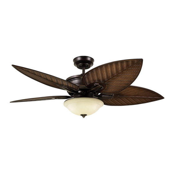
CALLITO COVE
52" Wet Location
Ceiling Fan Owner's Manual
Model Number
CF135DBZ00 -
Distressed Bronze
29.3
Net Weight:
Lbs.
Questions, problems, missing parts: Before returning to the store call
Emerson Electric Customer Service - 8 a.m. - 6 p.m., Eastern, Monday-Friday
1-800-654-3545
• Español - página 37
www.emersonfans.com
Part No. F40BP75180000
Form No. BP7518
Revision: 160524
U.L. Model No.: CF135
Table of Contents

Related Manuals for Emerson CALLITO COVE


Summary of Contents for Emerson CALLITO COVE
- Page 1 Distressed Bronze 29.3 Net Weight: Lbs. Questions, problems, missing parts: Before returning to the store call Emerson Electric Customer Service - 8 a.m. - 6 p.m., Eastern, Monday-Friday 1-800-654-3545 • Español - página 37 www.emersonfans.com Part No. F40BP75180000 Form No. BP7518 Revision: 160524 U.L.
-
Page 2: Table Of Contents
U.L. outlet boxes listed as “Acceptable for Fan Emerson Electric Co. could result in personal injury Support of 22.7kg. (50 lbs.) or less”, and use the mounting or property damage. -
Page 3: Unpacking Instructions
Hanger Bracket Emerson Electric Co. Substitution of parts or Hanger Ball/4.5” Downrod accessories not designated for use with this product by Emerson Electric Co. could result in personal injury Fan Blades Flanges or property damage. Fan Blades Receiver Remote Control Open carton containing fan. -
Page 4: Electrical Requirements
THIS FAN IS SUITABLE FOR WET LOCATIONS SUCH AS PORCHES, PATIOS, AND DECKS. USE ONLY WITH LIGHT KITS MARKED SUITABLE FOR USE IN WET LOCATIONS. Tools Needed for Assembly This Emerson Ceiling Fan may be used with the following accessory (purchased separately): Phillips head screwdriver... -
Page 5: Ceiling Fan Assembly
3. Ceiling Fan Assembly GREEN GROUND WIRE Remove the hanger ball by loosening the Phillips head setscrew in the hanger ball until the ball falls freely down the 4.5” downrod (Figure 1). 4.5" DOWNROD Remove the pin from the 4.5” downrod, then remove the hanger ball (Figure 1). - Page 6 3. Ceiling Fan Assembly (Continued) Align the clevis pin holes in the downrod with the holes in the motor coupler. Install the clevis pin and secure with the hairpin clip (Figure 4). HAIRPIN The clevis pin must go through the holes in the motor CLIP MOTOR coupler.
- Page 7 3. Ceiling Fan Assembly (Continued) Route the three 80” motor leads through the hanger ball RETAINER PIN DOWNROD (Figure 7). Locate the previously removed retainer pin from the downrod and insert it into the holes at the top of the downrod, as shown (Figure 7).
- Page 8 3. Ceiling Fan Assembly (Continued) The fan comes with black, blue and white leads that are 80-inches long. Measure up approximately 6 to 9-inches above top of hanger ball/4.5” downrod assembly (Figure 9). Cut off excess leads and strip back insulation 1/2-inch from end of leads using wire strippers.
- Page 9 3. Ceiling Fan Assembly (Continued) 3.11 BLADE/FLANGE INSTALLATION: PLAIN SIDE OF FAN BLADE Mount fan blade flange to the decorative bottom surface #10-24 x 0.4" FLANGE blade shown) using three HEAD SCREW (3 per flange/blade) #10-24 x .0.4” flange head blade screws using a Phillips head screwdriver (Figure 11).
-
Page 10: Switch Cover Assembly Only
4. Switch Cover Assembly Only This Ceiling Fan can be Installed Without the Light Kit. If you would like to Install your Fan Without a Light Kit, Please Follow the Below Instructions of Section 4. Skip to Section 5 if you Wish to Install the Light Kit Assembly on Your Ceiling Fan. If the Light Kit Assembly is Already Assembled to the Fan, and You Want to Remove it, Reverse Section 5 Assembly Instructions to Uninstall the Light Kit Assembly and Then Follow Section 4 Instructions to Disassemble the Light Kit Fitter from the Switch Cover. - Page 11 4. Switch Cover Assembly Only (Continued) 14 mm END WRENCH On the center threaded nipple of the switch cover, you will find a hex nut and lockwasher. HEX NUT Loosen and remove the hex nut with a 14 mm end wrench, and the lockwasher (Figure 16).
- Page 12 4. Switch Cover Assembly Only (Continued) Straighten the frayed strands of the switch cover blue and WIRE CONNECTOR WIRE CONNECTOR white wires in preparation to re-install the wire connectors. Using the two saved wire connectors, attach one connector to the bare blue wire and one connector to the SWITCH bare white wire of the switch cover by twisting the COVER...
- Page 13 4. Switch Cover Assembly Only (Continued) RUBBER PLUG Locate the rubber plug from the hardware pack and install BLADE it into the blade installation slot of the switch housing plate INSTALLATION NOTE: The rubber plug must be installed to prevent by firmly pushing it into the slot (Figure 21).
- Page 14 4. Switch Cup Assembly Only (Continued) 4.11 Securely reinstall the three previously removed #8-32 x 0.3” flat head screws into the aligned holes with a SWITCH phillips screwdriver (Figure 24). COVER Installation of the switch cover is now complete, skip Section 5 and proceed to Section 6. A spare #8-32 x 0.3”...
-
Page 15: Light Kit Assembly
5. Light Kit Assembly (Continued) Light Kit Fitter Has to be Attached to the Switch Cover LIGHT KIT ASSEMBLY to Proceed. Position the light kit assembly near the switch housing plate. Align and engage the large white light kit electrical connector with the large white motor electrical connector. - Page 16 6. How to Hang Your Ceiling Fan WARNING CEILING The fan must be hung with at least 7' of clearance from floor to blades (Figure 30). WARNING To avoid possible electrical shock, be sure electricity is turned off at the main fuse box before wiring. NOTE: If you are not sure if the outlet box is grounded, AT LEAST 7 ft.
-
Page 17: How To Hang Your Ceiling Fan
6. How to Hang Your Ceiling Fan (Continued) NOTE: CEILING COVER, SUPPLY WIRES AND FAN WIRES Carefully lift the partially assembled ceiling fan and seat OMITTED FOR CLARITY. the hanger ball/downrod assembly on the hanger bracket that just attached outlet (Figure 32). -
Page 18: How To Wire Your Ceiling Fan
Turning off wall switch is not sufficient. To avoid possible by Emerson Electric Co. Substitution of parts or electrical shock, be sure electricity is turned off at the accessories not designated for use with this product by main fuse box before wiring. - Page 19 7. How to Wire Your Ceiling Fan (Continued) NOTE: Make all wiring connections using the wire connectors supplied in the hardware kit and remote control kit. Make sure that all connections are tight, including ground, and that no bare wire is visible at the wire connectors, except for the supply circuit ground wire.
- Page 20 7. How to Wire Your Ceiling Fan (Continued) Securely connect the receiver black wire (AC in L) to the supply black wire (hot) using the wire connector (supplied in parts bag) (Figure 36). WIRE CONNECTOR SUPPLY AND RECEIVER BLACK WIRES Figure 36 Securely connect the receiver white wire (TO MOTOR N) to the fan motor white wire using the wire connector...
- Page 21 7. How to Wire Your Ceiling Fan (Continued) Securely connect the receiver black wire (TO MOTOR L) to the fan motor black wire using the wire connector (supplied in parts bag) (Figure 38). SUPPLY AND RECEIVER BLACK WIRES WIRE CONNECTOR Figure 38 NOTE: Failure to properly connect the receiver wires will damage the device and render it non-operable.
- Page 22 7. How to Wire Your Ceiling Fan (Continued) While inserting the receiver fully into the hanger bracket, WIRE CONNECTORS turn leads upward and carefully push leads into the outlet (Tucked Inside box, with the white and green leads on one side of the Outlet Box) outlet box and position the black lead on the other side of the outlet box (Figure 40).
-
Page 23: Ceiling Cover Installation
8. Ceiling Cover Installation Screw the studs into the threaded holes on the bottom of the hanger bracket with your fingers (Figure 42). HANGER BRACKET THREADED STUDS (2) Figure 42 Lift the ceiling cover up to the threaded studs and turn until studs protrude through the holes in the ceiling cover (Figure 43). -
Page 24: Glass Shade Installation
8. Ceiling Cover Installation (Continued) Secure the ceiling cover in place by sliding a lockwasher and knurled knob onto the threaded stud and loosely tighten to keep the cover in place. Install the other lockwasher and knurled knob onto the second threaded stud (Figure 44). - Page 25 9. Glass Shade Installation (Continued) The finial nut, hex nut, and rubber washer are preassembled to the bottom of the light kit. Unscrew the finial nut and remove the hex nut and rubber washer (Figure 46). Keep these items on top of the ladder for reassembly after the glass shade is installed.
-
Page 26: Transmitter Battery Installation And Code Setting
FINIAL NUT Figure 48 10. Transmitter Battery Installation and Code Setting 10.1 Your Emerson Ceiling Fan/Light Remote Control consists of hand-held transmitter and a receiver which is mounted REMOTE CONTROL under the fan ceiling cover. The remote control is designed to separately control your ceiling fan speed and light intensity. - Page 27 PRESET MEMORY FEATURE REMOTE CONTROL TRANSMITTER Your Emerson receiver is equipped with a preset memory feature. If the AC supply to the receiver is powered through a wall switch, when the switch is turned OFF, the control will remember the light intensity and fan speed.
-
Page 28: Receiver Code Learning
11. Receiver Code Learning - Programming the Operating Frequency of the Receiver 11.1 The receiver must be programmed within 2 minutes of restoring electricity to the fan. Program the receiver code by pushing and holding down the remote control OFF REMOTE CONTROL button for 5-10 seconds. - Page 29 11. Receiver Code Learning - Programming the Operating Frequency of the Receiver (Continued) 11.3 INSTALLATION OF THE STORAGE BRACKET A storage bracket is provided for holding your remote STORAGE BRACKET control when not in use. If you desire to use the bracket, COVER install it on a wall that is away from excess heat or humidity (Figure 54).
-
Page 30: Using Your Ceiling Fan
12. Using Your Ceiling Fan 12.1 All fans are shipped from the factory with the reverse switch positioned to circulate air downward. The reverse switch is located on the side of the switch cover. The switch is covered with a soft rubber seal that protects it from water. -
Page 31: Maintenance
Emerson Electric Co. Substitution of parts or · Downrod Extension Kits accessories not designated for use with this product by Emerson Electric Co. could result in personal injury WARNING or property damage. The use of any other control not specifically approved for this fan could result in fire, shock and personal injury. -
Page 32: Troubleshooting
15. Troubleshooting WARNING FOR YOUR OWN SAFETY TURN OFF POWER AT FUSE BOX OR CIRCUIT BREAKER BEFORE TROUBLESHOOTING YOUR FAN. TROUBLE PROBABLE CAUSE SUGGESTED REMEDY 1.Fan will not start. 1. Loose electrical connections in the 1. Check the electrical connections at the ceiling ceiling cover. -
Page 33: Ceiling Fan Limited Warranty
Manual or other instructions provided by Emerson to you with the Emerson Ceiling Fan). LED drivers are covered for a period of three (3) years, and any LED array is covered for a period of five (5) years. All other components and accessories of the Emerson Ceiling Fan are covered by this limited warranty for a period of one (1) year. All warranty periods begin on the date of original retail purchase. -
Page 34: Repair Parts
16. Repair Parts PARTS BAG U.L. Model No.: CF135... - Page 35 16. Repair Parts Listing Model Number Description CF135DBZ00 Hanger Ball Assembly, 761655-81 Consisting of: Hanger Bracket (1) — Hanger Ball (1) — 4.5” Downrod (1) — Parts Bag Containing: 764793 Wire Connectors (3) — Studs, Threaded, #8-32 x 1-1/4” (2) —...
- Page 36 You should record this data above and keep it in a safe place for future use. Air Comfort Products DIVISION OF EmErSON ElEctrIc cO. 8100 W. Florissant • St. louis, mO 63136 Questions, problems, missing parts: Before returning to the store call Emerson Electric Customer Service 8 a.m.
-
Page 37: Spanish
29,3 Peso neto: Preguntas, problemas, piezas faltantes: Antes de devolver el producto a la tienda, llame al Servicio al Cliente de Emerson Electric — 8 a.m. a 6 p.m., Hora del Este, lunes a viernes 1-800-654-3545 www.emersonfans.com No. de pieza F40BP75180000 No. - Page 38 Locales. Utilice el Código Eléctrico Nacional si no existen cumplir con los requisitos de utilización en exteriores expuestos a precipitación. Consulte a servicio al cliente de Emerson llamando al 1- Códigos Locales. El ventilador de techo se debe conectar a tierra 800-654-3545 para obtener asistencia adicional.
- Page 39 Esfera de suspensión/varilla este producto. La sustitución con piezas o accesorios no descendente de 4,5 pulg. diseñados por Emerson Electric Co. para utilizarse con este Pestañas para paleta de ventilador producto podría causar lesiones corporales o daños materiales. Paletas del ventilador...
- Page 40 ESTE VENTILADOR ES ADECUADO PARA LUGARES HÚMEDOS, TALES COMO PORCHES CUBIERTOS, PATIOS CUBIERTOS Y TERRAZAS CUBIERTAS. UTILÍCELO SÓLO CON KITS DE LUZ MARCADOS COMO ADECUADOS PARA USO EN LUGARES HÚMEDOS. Este ventilador de techo Emerson se puede utilizar con el siguiente Herramientas necesarias accesorio (comprado por separado):...
- Page 41 3. Ensamblaje del ventilador de techo CABLE VERDE DE CONEXIÓN A TIERRA GREEN GROUND WIRE Retire la esfera de suspensión aflojando el tornillo de ajuste de cabeza Phillips ubicado en dicha esfera hasta que la misma caiga PASADOR libremente bajando por la varilla descendente de 4,5 pulgadas (Figura 1).
- Page 42 3. Ensamblaje del ventilador de techo (continuación) Alinee los agujeros para pasador de horquilla ubicados en la varilla descen dente con los agujeros ubicados en el acoplamiento del motor. Instale el pasador de horquilla y sujételo firmemente con el clip de horquilla (Figura HAIRPIN CLIP DE...
- Page 43 3. Ensamblaje del ventilador de techo (continuación) PASADOR DE Encamine los dos cables de conexión del motor de 80 pulgadas a RETAINER PIN RETENCIÓN VARILLA DOWNROD través de la esfera de suspensión (Figura 7). DESCENDENTE Localice el pasador de retención que se retiró previamente de la varilla descendente e insértelo en los agujeros ubicados en la parte superior de dicha varilla, de la manera que se muestra en la ilustración (Figura 7).
- Page 44 3. Ensamblaje del ventilador de techo (continuación) El ventilador viene con cables de conexión de color azul, negro y blanco que tienen 80 pulgadas de longitud. Mida hacia arriba aproximadamente de 6 a 9 pulgadas por encima de la parte superior del ensamblaje de esfera de suspensión/varilla descendente de 4,5 pulgadas (Figura 9).
- Page 45 3. Ensamblaje del ventilador de techo (continuación) 3.11 LADO LISO DE LA PALETA PLAIN SIDE OF DEL VENTILADOR FAN BLADE INSTALACIÓN DE LAS PALETAS/PESTAÑAS: Monte la pestaña para paleta del ventilador en la superficie decorativa #10-24 x 0.4" FLANGE TORNILLO CON CABEZA DE inferior de la paleta del ventilador (de la manera que se muestra en la PESTAÑA #10-24 x 0,4 PULG.
- Page 46 4. Ensamblaje de la cubierta del interruptor solamente Este ventilador de techo se puede instalar sin el kit de iluminación. Si desea instalar el ventilador sin kit de iluminación,por favor, siga las instrucciones de la Sección 4 que se encuentran a continuación. Vaya a la Sección 5 si desea instalar el ensamblaje del kit de iluminación en el ventilador de techo.
- Page 47 4. Ensamblaje de la cubierta del interruptor solamente (continuación) 14 mm END WRENCH LLAVE DE BOCA FIJA DE 14 mm En el niple roscado central de la cubierta del interruptor encontrará una tuerca hexagonal y una arandela de seguridad. TUERCA HEXAGONAL HEX NUT Afloje y retire la tuerca hexagonal con una llave de boca fija de 14 mm y retire también la arandela de seguridad (Figura 16).
- Page 48 4. Ensamblaje de la cubierta del interruptor solamente (continuación) CONECTOR DE CABLES Enderece las hebras deshilachadas de los cables azul y blanco de la WIRE CONNECTOR WIRE CONNECTOR CONECTOR DE CABLES cubierta del interruptor en preparación para reinstalar los conectores de cables.
- Page 49 4. Ensamblaje de la cubierta del interruptor solamente (continuación) TAPÓN DE CAUCHO RUBBER PLUG Localice el tapón de caucho en el paquete de herrajes e instálelo en RANURA DE BLADE la ranura de instalación de la paleta ubicada en el plato de la carcasa INSTALACIÓN INSTALLATION DE LA PALETA...
- Page 50 4. Ensamblaje de la cubierta del interruptor solamente (continuación) 4.11 Reinstale firmemente los tres tornillos de cabeza plana núm. 8-32 x 0,3 pulgadas, retirados previamente, en los agujeros alineados, SWITCH CUBIERTA DEL utilizando un destornillador Phillips (Figura 24). COVER INTERRUPTOR Una vez hecho esto se habrá...
- Page 51 5. Ensamblaje del kit de iluminación (continuación) LIGHT KIT ASSEMBLY ENSAMBLAJE DEL KIT DE ILUMINACIÓN El ajustador del kit de iluminación tiene que estar sujeto a la cubierta del interruptor para seguir adelante. Posicione el ensamblaje del kit de iluminación cerca del plato de la carcasa del interruptor.
- Page 52 6. Cómo colgar su ventilador de techo ADVERTENCIA TECHO CEILING El ventilador se debe colgar con por lo menos 7 pies de holgura desde el piso hasta las paletas (Figura 30). ADVERTENCIA Para evitar posibles descargas eléctricas, asegúrese de que la electricidad esté...
- Page 53 6. Cómo colgar su ventilador de techo (continuación) NOTA: LA CUBIERTA DEL TECHO, LOS CABLES DE ALIMENTACIÓN Y LOS CABLES NOTE: CEILING COVER, SUPPLY WIRES AND FAN WIRES Levante cuidadosamente el ventilador de techo parcialmente DEL VENTILADOR SE HAN OMITIDO PARA OFRECER MAYOR CLARIDAD. OMITTED FOR CLARITY.
- Page 54 La sustitución con piezas o accesorios no apagado. Para evitar una posible descarga eléctrica, asegúrese diseñados por Emerson Electric Co. para utilizarse con este de que la electricidad esté desconectada en la caja de fusibles producto podría causar lesiones corporales o daños materiales.
- Page 55 7. Cómo cablear su ventilador de techo (continuación) NOTA: Haga todas las conexiones de cableado utilizando los conectores de cables suministrados en el kit de herrajes y en el kit del control remoto. Asegúrese de que todas las conexiones estén apretadas, incluyendo la conexión a tierra, y que no haya cables pelados visibles en los conectores de cables, excepto el cable de conexión a tierra del circuito de suministro.
- Page 56 7. Cómo cablear su ventilador de techo (continuación) Conecte firmemente el cable negro del receptor (AC in L) (ENTRADA DE CA CON V) al cable blanco de suministro (con corriente) utilizando el conector de cables (suministrado en la bolsa de piezas) (Figura 36).
- Page 57 7. Cómo cablear su ventilador de techo (continuación) Conecte firmemente el cable negro del receptor (TO MOTOR L) (AL MOTOR CON V) al cable negro del motor del ventilador utilizando el conector de cables (suministrado en la bolsa de piezas) (Figura 38). CABLES NEGROS DE SUMINISTRO SUPPLY AND RECEIVER Y DEL RECEPTOR...
- Page 58 7. Cómo cablear su ventilador de techo (continuación) Mientras inserta completamente el receptor en el soporte de WIRE CONECTORES DE CONNECTORS suspensión, gire los hilos de conexión hacia arriba y empújelos CABLES (introducidos (Tucked Inside por completo en la cuidadosamente hacia el interior de la caja de tomacorriente, con los Outlet Box) caja de tomacorriente) hilos de conexión blanco y verde en un lado de la caja de...
- Page 59 8. Instalación de la cubierta del techo Enrosque con los dedos los espárragos en los agujeros roscados ubicados en la parte inferior del soporte de suspensión (Figura 42). HANGER BRACKET ESFERA DE SUSPENSIÓN THREADED STUDS (2) ESPÁRRAGOS ROSCADOS (2) Figura 42 Suba la cubierta del techo hasta los espárragos roscados y gírela hasta que dichos espárragos sobresalgan a través de los agujeros de la cubierta del techo (Figura 43).
- Page 60 8. Instalación de la cubierta del techo (continuación) Sujete la cubierta del techo en la posición deseada, deslizando una arandela de seguridad y un pomo estriado por el espárrago roscado, y apriete dicho pomo flojamente para mantener la cubierta en la posición deseada.
- Page 61 9. Instalación de la pantalla de vidrio (continuación) La tuerca de remate, la tuerca hexagonal y la arandela de caucho están preensambladas en la parte inferior del kit de iluminación. Desenrosque la tuerca de remate y retire la tuerca hexagonal y la arandela de caucho (Figura 46).
- Page 62 Figura 48 10. Instalación de la batería del transmisor y configuración del código 10.1 El control remoto del ventilador de techo/luz Emerson consiste en un transmisor de mano y un receptor que está montado dentro de la CONTROL REMOTO REMOTE CONTROL cubierta del ventilador de techo.
- Page 63 TRANSMITTER CONTROL REMOTO FUNCIÓN DE MEMORIA PREESTABLECIDA El receptor Emerson está equipado con una función de memoria preestablecida. Si la alimentación de CA al receptor se controla mediante un interruptor de pared, al poner el interruptor en la posición de APAGADO, el control recordará la intensidad de la luz y la velocidad del ventilador.
- Page 64 11. Aprendizaje del código del receptor: Programación de la frecuencia de operación del receptor 11.1 El receptor se debe programar dentro del plazo de 2 minutos después de restaurar el suministro eléctrico al ventilador. Programe CONTROL REMOTO REMOTE CONTROL el código del receptor presionando y manteniendo presionado el botón de APAGADO del control remoto durante 5-10 segundos.
- Page 65 11. Aprendizaje del código del receptor: Programación de la frecuencia de operación del receptor (continuación) 11.3 INSTALACIÓN DEL SOPORTE DE ALMACENAMIENTO Se suministra un soporte de almacenamiento para sostener el CUBIERTA DEL STORAGE SOPORTE DE BRACKET control remoto cuando no se esté utilizando. Si desea usar el ALMACENAMIENTO COVER soporte, instálelo en una pared que esté...
- Page 66 12. Utilización del ventilador de techo 12.1 Todos los ventiladores se envían desde la fábrica con el interruptor de inversión posicionado para que el aire circule hacia abajo. El interruptor de inversión está ubicado en un lado de la cubierta del interruptor.
- Page 67 14. Accesorios ADVERTENCIA Vea a su distribuidor local de Emerson, visite www.emersonfans.com o consulte el Catálogo de ventiladores de techo Emerson acerca de estos accesorios: Este producto está diseñado para utilizar únicamente las piezas suministradas con este producto y/o los accesorios diseñados ·...
- Page 68 15. Resolución de problemas ADVERTENCIA PARA SU PROPIA SEGURIDAD, DESCONECTE LA ALIMENTACIÓN ELÉCTRICA EN LA CAJA DE FUSIBLES O EL CORTACIRCUITO ANTES DE RESOLVER PROBLEMAS EN SU VENTILADOR PROBLEMA CAUSA PROBABLE REMEDIO SUGERIDO 1. El ventilador 1. Conexiones eléctricas flojas en la cubierta 1.
- Page 69 Lo que haremos para corregir los problemas: Si durante el período de garantía de un (1) año el motor o cualquier componente o accesorio de su Ventilador de Techo Emerson presenta defectos de materiales o de fabricación, o si durante el tiempo de vida útil esperado del Ventilador de Techo Emerson (cuando se utilice de acuerdo con el Manual del Usuario u otras instrucciones) el motor presenta defectos de materiales o de fabricación, usted debe ponerse en contacto con su distribuidor local durante el período de garantía aplicable.
- Page 70 16. Piezas de repuesto PARTS BAG BOLSA DE PIEZAS No. de modelo UL: CF135...
- Page 71 16. Lista de piezas de repuesto Número de modelo de clave Descripción CF135DBZ00 Ensamblaje de la esfera de suspensión, 761655-81 que consiste en: Soporte de suspensión (1) — Esfera de suspensión (1) — Varilla descendente de 4,5 pulgadas (1) — Bolsa de piezas que contiene: 764793 Conectores de cables (3)
- Page 72 DIVISION OF EmErSON ElEctrIc cO. 8100 W. Florissant • St. louis, mO 63136 Preguntas, problemas, piezas faltantes: Antes de devolver el producto a la tienda, llame al Servicio al Cliente de Emerson Electric 8 a.m. a 6 p.m., Hora del Este, lunes a viernes 1-800-654-3545 www.emersonfans.com...