Table of Contents
Quick Links
Table of Contents

Related Manuals for Emerson Liebert NPS


Summary of Contents for Emerson Liebert NPS
- Page 1 Pow er Switch Liebert NPS Network Power Switch SWAP Manual Reference: 6390060O-En (03/04) Rev ENPAu 05/2004...
- Page 3 It is our constant endeavour to partner you for the growth and success of your business. This philosophy is reflected in our Mission statement “To deliver value through Air & Power Quality solutions to achieve customer delight”. Please do give us feedback to help us realize our Mission. EMERSON NETWORK POWER...
- Page 5 Liebert Sales Office from whom the equipment was purchased. Alternatively, contact the Liebert's Customer Service & Support department at the address shown below: Emerson Network Power Ltd - United Kingdom Fourth Avenue, Globe Park Marlow Buckinghamshire SL71YG...
- Page 6 USER MANUAL Safety Precautions CONFORMITY AND STANDARDS This equipment complies with the following requirements: Normative references: Safety: * EN 50178 EMC: * EN61000-6-2 (2001-10;immunity) * EN61100-6-3(emission) The equipment must be installed in accordance with these instructions and used only with accessories approved by the manufacturer to maintain conformity with the standards.
-
Page 7: Table Of Contents
USER MANUAL Table of Contents Chapter 1 – General description ..........................1-1 1.1 Introduction ................................1-1 1.2 Design Concept................................. 1-2 1.3 Mechanical Design Description..........................1-3 1.4 Mimic Indications ..............................1-4 1.5 Manual Bypass Switch Operation ..........................1-5 1.6 Potential free contacts ............................... 1-6 Chapter 2 –... - Page 8 USER MANUAL This manual describes the following equipment: EQUIPMENT PART NUMBER 6 kVA Pole Network Power Switch SSWITCH-25A Important Support Information: If you require assistance for any reason, please have the following information available: Model and size Serial number Date installed Location Voltage &...
-
Page 9: Chapter 1 - General Description
User Manual Chapter 1 - General Description 1 Chapter 1 – General description 1.1 Introduction The Network Power Switch is an automatic static transfer switch designed to provide fast automatic transfers between two independent, synchronous AC power sources to provide continuity of AC power to critical equipment, such as information technology equipment. -
Page 10: Design Concept
Chapter 1 - General Description User Manual 1.2 Design Concept Figure 5.1.1 in Chapter 5 shows the Power circuit diagram for Network Power Switch. Source 1 & Source 2 are the two synchronized power sources with fuse switches FS1 & FS2 & pair of SCR’s TA1 & TB1 in series with each path &TA2 and TB2 in the neutral path Logic dictates that at any time only one pair of back-to-back connected SCR’s in the line and neutral should conduct. -
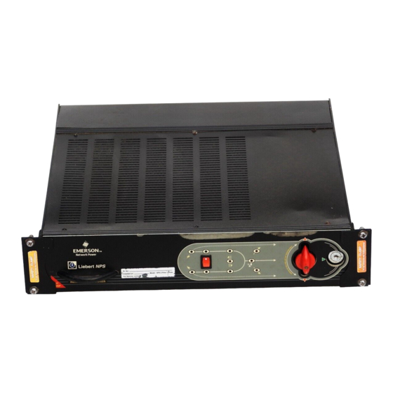
Page 11: Mechanical Design Description
User Manual Chapter 1 - General Description 1.3 Mechanical Design Description FIXED UNIT HOT SWAPPABLE UNIT Fig 1.3 – Hot swappable and Fixed Unit The Network Power Switch consists of two modules. Fixed module consists of the input and output connections and manual bypass transfer control switch. Second module is hot swappable plug-in type with removable electronics &... -
Page 12: Mimic Indications
Chapter 1 - General Description User Manual 1.4 Mimic Indications S1 Healthy S1 Priority S1 Feeding Load on S1 Priority Selection OverLoad on Super Switch Switch Load on S2 Unsynchronised transfer S2 Healthy S2 Priority S2 Feeding Fig 1.4 – Mimic and LED Indications LED INDICATION Mimic indications: Ten LEDs are mounted on the mimic plate;... -
Page 13: Manual Bypass Switch Operation
User Manual Chapter 1 - General Description 1.5 Manual Bypass Switch Operation BYPASS ON S1 SOURCE YELLOW LED (LOAD ON S1) OUTPUT YELLOW LED (LOAD ON S2) BYPASS ON S2 SOURCE Fig 1.5 – Manual Bypass Switch Operation Manual Bypass switch is used only when a fault occurs in the Network Power Switch and the control circuitry of the Network Power Switch is to be checked. -
Page 14: Potential Free Contacts
Chapter 1 - General Description User Manual Operating Network Power Switch in Bypass mode • Insert the Hot swappable module into the Network Power Switch unit • Lock the sliding module for preventing its accidental opening. • Unlock the Manual Bypass Switch with the key provided •... -
Page 15: Chapter 2 - Operating Instructions
User Manual Chapter 2 – Operating Instructions Chapter 2 – Operating Instructions 2.1 Introduction The Network Power Switch can be considered to be in one of the three operating conditions: • Normal Operation - All relevant power switches and fuses closed and the Load is connected to Network Power Switch output •... -
Page 16: Switching The Load To Manual Bypass Condition
Chapter 2 – Operating Instructions User Manual 2.4 Switching the Load to Manual Bypass condition BYPASS ON S1 SOURCE YELLOW LED (LOAD ON S1) OUTPUT (NOT CONNECTED) YELLOW LED (LOAD ON S2) ‘ON’ BYPASS ON S2 SOURCE (LOAD CONNECTED TO THIS BYPASS) Fig 2.2 –... -
Page 17: Chapter 3 - Installation Procedure
User Manual Chapter 3 - Installation Procedure 3 Chapter 3 – Installation Procedure 3.1 Introduction WARNING Do not apply electrical power to the Network Power Switch equipment before the arrival of the commissioning engineer. WARNING The Network Power Switch equipment should be installed by a qualified engineer in accordance with the information contained in this chapter and the drawing package shipped inside UPS cabinet. -
Page 18: Connecting Cables To Network Power Switch
Chapter 3 - Installation Procedure User Manual 3.3 Connecting cables to Network Power Switch WARNING BEFORE CABLING-UP THE NETWORK POWER SWITCH, ENSURE THAT YOU ARE AWARE OF THE LOCATION AND OPERATION OF THE EXTERNAL ISOLATORS THAT CONNECT THE NETWORK POWER SWITCH INPUT SUPPLY TO THE MAINS DISTRIBUTION PANEL. CHECK THAT THESE SUPPLIES ARE ELECTRICALLY ISOLATED, AND POST ANY NECESSARY WARNING SIGNS TO PREVENT THEIR INADVERTENT OPERATION. -
Page 19: Protective Devices
User Manual Chapter 3 - Installation Procedure 3.3.5 Protective devices For safety reasons, it is necessary to install external to the Network Power Switch system, circuit breaking protective devices in the input a.c. supply and towards the output. Given that every installation has its own characteristics, this chapter provides general useful information for qualified installation engineers, with knowledge of operating practices, of regulatory standards, and of the equipment to be installed. - Page 20 Chapter 3 - Installation Procedure User Manual This page is left blank intentionally Page 3-4 (03/04)
-
Page 21: Chapter 4 - Specifications
User Manual Chapter 4 – Specifications 4 Chapter 4 - Specifications 4.1 Conformity and Standards This equipment complies with the following requirements: Normative references: Safety: * EN 50178 EMC: * EN61000-6-2 (2001-10;immunity) * EN61100-6-3(emission) The equipment must be installed in accordance with these instructions and used only with accessories approved by the manufacturer to maintain conformity with the standards. -
Page 22: Electrical Specifications
Chapter 4 – Specifications User Manual 4.4 Electrical Specifications ELECTRICAL UNITS DESCRIPTION CHARACTERISTICS Nominal Input Voltage 220, 230 or 240 volts single phase a.c., 2W+G, 50 Hz. Power supply Solidly grounded power sources Nominal Output current Amps Frequency 50 / 60 Source unhealthy status Guaranteed Transfer to alternate source –15 % of V nominal Load Power factor range... -
Page 23: Installation Drawings
User Manual Chapter 5 – Installation Drawing Installation Drawings 5.1.1 Power Circuit Diagram 5.1.2 External Power cable connections 5.1.3 Overall general arrangement (03/04) Page 5-1... - Page 24 Chapter 5 – Installation Drawing User Manual 5.1.1 Power Circuit Diagram RC SNUBBER EMI FILTER PCB X6:1 50A SWITCH FUSE L1-1 OUTPUT SW1 (MANUAL BYP. SWITCH) X6:3 L1-2 OUTPUT X6:2 OUTPUT 50A SWITCH FUSE X6:4 N1 L2 CN11 SOURCE 1 INPUT PCB - MIMIC S1 HEALTHY SOURCE 2 INPUT...
-
Page 25: External Power Cable Connections
Chapter 5 – Installation Drawing 5.1.2 External Power cable connections Input Fuse 2 Input Fuse 1 Snap-on Connector External Cables Earthing Rear View EXTERNAL POWER CABLE CONNECTIONS NETWORK POWER SWITCH (03/04) Page 5-3... -
Page 26: Overall General Arrangement
Chapter 5 – Installation Drawing User Manual 5.1.3 Overall general arrangement 431 mm Liebert NPS Networ k Power Switc h SWAP SWAP 465 mm 483 mm Page 5-4 (03/04) -
Page 27: Limited Warranty
If the Liebert NPS fails to conform with the above warranty within the two year warranty period, Liebert will repair or replace the system, at Liebert's option. Repairs or replacements are warranted for the remainder of the original warranty period.