
Related Manuals for Emerson 110V


Summary of Contents for Emerson 110V
- Page 1 Liebert NPS Network Power Switch SWAP (07/04)
- Page 2 Please accept our thanks for giving us the privilege to serve you by choosing a Liebert make product. If this is your first Liebert product, we hope it is the beginning of a long relationship which delivers value to your organisation. If you already own and use a Liebert product, we are doubly honoured by your decision of continuing this relationship.
- Page 3 If you encounter any problems with the procedures contained in this manual you should seek immediate assistance from the Liebert Sales Office Liebert Corporation pursues a policy of continual product development and reserves the right to change the ENGLISH from whom the equipment was purchased.
- Page 5 USER MANUAL EMERSON NETWORK POWER (India) Pvt. Ltd. Thane – 400 604 Maharashtra, India TELEPHONE: (00 91 22) 5807000, 5828405 (opp. Shreyas cinema), LBS Road, Ghatkopar(W), MUMBAI – 400 086 Tel : 022-5002318, 5002294, 5002437 Fax: 022-5002415 Mobile : 9820030917, 9820030915 18 / 14, WEA, Pusa Lane, Karol Baug;...
- Page 6 Branch Offices: BARODA 39 / 2, Arunodaya Society, Alkapuri, BARODA-390 005 Tel : 0265-314296, 330383 Fax: 0265-314296, 330383 CHANDIGARH SCO-198 / 199 / 200, Sector – 34A, Near Labour Chowk, CHANDIGARH Phone: 0172-662 873 Mobile: 9814100901 CHENNAI No. 22, First Floor, Gopal Krishna Road, T.
-
Page 7: Conformity And Standards
Safety Precautions Personnel operating on any apparatus referred in this manual must know extensively the product. The Network Power Switch must be commissioned and serviced by an engineer approved by the manufacturer (or his agent). Failure to do so could result in personnel safety risk, equipment malfunction and invalidation of warranty. -
Page 8: Table Of Contents
Introduction... 2-1 General Notes... 2-1 Procedure for Switching the Network Power Switch to power the load from a Power Off condition... 2-1 Switching the Load to Manual Bypass condition ... 2-2 Procedure for switching the Network Power Switch from Manual Bypass condition to Normal Operation... 2-2 Chapter 3 –... - Page 9 USER MANUAL This manual describes the following equipment: EQUIPMENT 3kVA, 110V, 25A, 1 Pole Network Power Switch (Rev00) PART NUMBER 492100399001 Page v...
-
Page 11: Chapter 1 - General Description
One of the two AC inputs is designed as the “preferred” source to which the Network Power Switch will connect the load as long as the designated input source is within the acceptable limits, the Network Power Switch is designed to transfer the output load to the “alternate “input source, as long as the alternate source is within the acceptable voltage... -
Page 12: Design Concept
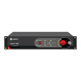
Priority source can be selected through front panel switch. The live mimic on front panel indicates which source is on priority & which is feeding the load. Figure 1.4 shows the details of live mimic panel. -
Page 13: Mechanical Design Description
Second module is hot swappable plug-in type with removable electronics & static switching module. The bypass / transfer control switch is located on right side of the cabinet with a key lock to restrict access to qualified or designated operators. The plug in module likewise contains locked latches to prevent unauthorized removal of the module. -
Page 14: Mimic Indications
S2 Healthy LED INDICATION Mimic indications: Ten LEDs are mounted on the mimic plate; Glowing LED’s indicate the status of the Network Power Switch. S1 Healthy: Source –1 is a healthy source and is well above the 10% under voltage setting. -
Page 15: Manual Bypass Switch Operation
(LOAD ON S2) Manual Bypass switch is used only when a fault occurs in the Network Power Switch and the control circuitry of the Network Power Switch is to be checked. For doing this operation the load is connected to the bypass. For Normal Operation, the position of the switch should be at Network Power Switch output position (i.e. -
Page 16: Potential Free Contacts
Chapter 1 - General Description 1.6 Potential free contacts The Network Power Switch status can be checked with the 37-pin D-type connector, located on the rear end. This is a potential free contact, and gives following indications as shown in Table 1-1 –... -
Page 17: Chapter 2 - Operating Instructions
This procedure should be followed when turning on the Network Power Switch from a fully powered down condition -i.e. when the load is not being initially supplied at all. It is assumed that the installation is complete; the authorized personnel have commissioned the system. -
Page 18: Switching The Load To Manual Bypass Condition
By seeing the LED indication check which source is feeding. Unlock the Bypass switch lock by the using the key provided. Rotate the Manual Bypass switch in the direction of the source feeding the load as per the warning given on the mimic. -
Page 19: Chapter 3 - Installation Procedure
3.2 Equipment positioning and environmental considerations The Network Power Switch cabinets are designed to fit in standard 19-inch rack. In case of non-availability, it can be kept on floor or as a tabletop item, with sufficient ground clearance. -
Page 20: Connecting Cables To Network Power Switch
CHECK THAT THESE SUPPLIES ARE ELECTRICALLY ISOLATED, AND POST ANY NECESSARY WARNING SIGNS TO PREVENT THEIR INADVERTENT OPERATION. 3.3.1 Cable entry Cable enter the Network Power Switch cabinet, from the rear side as shown in figure 3.2. The cables are terminated on the connectors and fuses. 3.3.2 Cable Rating Following are the recommended cable size for 6kVA Network Power Switch –... -
Page 21: Cable Connections
User Manual 3.3.3 Cable connections Following are the set of external power cables, which are connected to the Network Power Switch equipment – • Input source 1 – Line • Input source 2 – Line • Input source 1 – Neutral •... - Page 22 Chapter 3 – Installation Procedure Page 3-4 User Manual...
-
Page 23: Chapter 4 - Specifications
Hot swappable electronic static switching module • Live mimic on Hot swappable unit for indicating load supply status & alarms • Make before break manual bypass switch to transfer load from static switch to direct source 1 or source 2 4.2 Electrical Specifications ELECTRICAL CHARACTERISTICS... -
Page 24: Mechanical Specifications
Chapter 3 – Installation Procedure 4.3 Mechanical specifications MECHANICAL UNITS CHARACTERISTICS Height Width Depth Weight Colour Installation Cable entry Ingress Protection 4.4 Environmental specifications ENVIRONMENTAL UNITS CHARACTERISTICS Heat dissipation Storage temp. range Operating temp. range Relative humidity Operating altitude Storage / Transport Altitude Audible Noise Page 4-2 DESCRIPTION... - Page 25 User Manual Chapter 3 – Installation Procedure Page 4-3...
-
Page 27: Installation Drawings
User Manual Installation Drawings 5.1.1 Power Circuit Diagram 5.1.2 External Power cable connections 5.1.3 Overall general arrangement (02/04) Chapter 5 – Installation Drawing Page 5-1... - Page 28 Chapter 5 – Installation Drawing 5.1.1 Power Circuit Diagram Page 5-2 (02/04) User Manual...
-
Page 29: External Power Cable Connections
5.1.2 External Power cable connections External Cable External Cables Potential Free Contacts EXTERNAL POWER CABLE CONNECTIONS Input Fuse 2 Input Fuse 1 Earthing Rear View NETWORK POWER SWITCH (02/04) Chapter 4 – User Manual Snap-on Connector Page 5-3... -
Page 30: Overall General Arrangement
Chapter 5 – Installation Drawing 5.1.3 Overall general arrangement Page 5-4 431 mm Liebert NPS Networ k Power Switc h SWAP SWAP 465 mm 483 mm (02/04) User Manual... - Page 31 (02/04) Chapter 4 – User Manual Page 5-5...